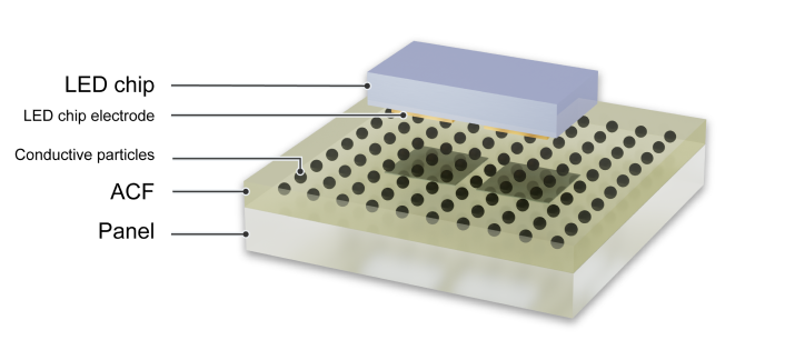
The Micro LED display is a display technology that is drawing the attention of electronics manufacturers around the world. After many years in research and development, the technology has entered the commercialization phase and is expected to spread at a rapidly increasing pace. This article will explore the basic characteristics of the Micro LED display, the newest trends, and the challenges it faces. It will also explain in detail the changes that ArrayFIX, a particle-arrayed ACF product from Dexerials, can bring to Micro LED display technology.
Micro LED chips are microscopic LED chips less than 0.1 millimeters in size. Display technology using these Micro LED chips takes smaller versions of the LEDs used as light sources in everyday lighting and traffic lights and arranges them across entire display panels. This allows displays to leverage LED’s characteristics of high brightness, low power consumption, and long lifespans while using the small LED chips to create detailed images.
Micro LED displays produce rich, painting-like images by precisely controlling the color and brightness of each pixel. This technology is based on the same principle behind the large screens seen in sports stadiums. But Micro LED displays use smaller individual light sources to produce highly detailed images viewable from a close distance. A Micro LED chip is less than half the size of a standard LED, and some are less than 1/6 of the size.
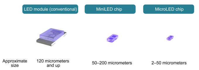
As the technology evolves, Micro LEDs are being considered for use in a wide range of devices such as digital signage, televisions, wearable devices, and augmented reality (AR) smart glasses. By enabling smaller and more sophisticated displays, Micro LED technology has the potential to contribute to significant advances in electronic devices.
There are, however, multiple obstacles to the widespread use of Micro LED displays.
One such obstacle is cost. The price tags of about 80,000 USD on an 89-inch display and about 150,000 USD on a 110-inch display launched in 2022 illustrate this. As of January 2024, a major South Korean electronics manufacturer sells Micro LED displays for TVs but the prices are still higher than the price range for the average consumer. The cost of the Micro LED chips themselves is one factor in the high prices, but it is thought that the lack of an established, efficient manufacturing process is also a factor. This may mean that manufacturing costs have not been reduced as much as expected.
Another big challenge is the LED arrangement process (mass transfer). When manufacturing a Micro LED display, more than 24 million red, green, and blue LED elements are necessary to form the more than 8 million pixels for a 4K display. A method called “pick and place” is used to position these LED elements on the circuit board. An elastomer stamp is used to pick up LED chips and transport them to the target location. There is a limit to the number of LED chips that can be moved at once, resulting in the problem of extremely long times required to move all of the chips.
Another bottleneck in the manufacturing process is low illumination rate and the repair of non-illuminating parts. The LED chips used to produce high-resolution images are so small that connection to the circuit board becomes difficult, leading to an increased trend in non-illumination. When an LED chip fails to illuminate, it leads to a pixel defect where it cannot show the correct color, or in the worst case a dead pixel. A partial repair is necessary to address the issue.
To take on these challenges, various manufacturers are developing assembly process technologies such as batch formation of LEDs on wafers and mass transfer of LED chips. Many other manufacturing approaches are also being tried. One is “tiling,” which arranges small LED displays like tiles to create one large display. Others involve sealing or laminating LED chips.
As Micro LED display technology continues to evolve, Dexerials provides products that can play important roles in Micro LED display manufacturing. In addition to products such as optical films and optical elastic resins, Anisotropic Conductive Film (ACF) is drawing attention as an indispensable part of electrically connecting various parts of the display. In particular, a particle-arrayed ACF called ArrayFIX was developed for the miniaturization of terminal connections such as those found on Micro LED chips, and its potential applications have been highly evaluated.
As the connection area between LED chips and substrate shrinks in the Micro LED display manufacturing process, ArrayFIX continues to evolve to meet that challenge. Specifically, the diameter of conductive particles is smaller than in previous products, resulting in higher particle density that enables greater precision in positioning.
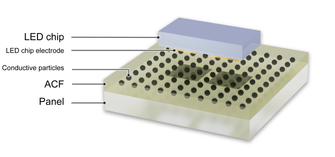
Previously, the highest density ArrayFIX ACF had a particle diameter of 3.2 micrometers and a particle density of 28 kpcs/mm2, designed for Chip on Glass (COG) technology to mount ICs for high-resolution displays such as those for smartphones. However, ArrayFIX for Micro LEDs requires even higher precision, so we are designing a version with particle diameter reduced to 2.2 micrometers and particle density increased to 58 kpcs/mm2.
ArrayFIX for Micro LEDs enables stable connections due to the arrayed particles and low-resistance connection to extremely small electrodes of 100 μm² and below. Additionally, because the particles maintain their positions, excellent insulation is provided even with extremely small distances between electrodes.
The use of ArrayFIX can simplify the manufacturing process by enabling processing at lower temperatures than those required for conventional solder bonding and removing the need for Au/Sn bump formation. Simply applying ACF to the substrate is all the preparation that is required. With less pre-processing needed compared to other bonding methods, significant time and cost savings can be expected. In addition, temporary fixing of LEDs during mass transfer is possible between room temperature and 50°C, followed by thermocompression bonding all at once later. This can increase the efficiency of large-scale display manufacturing.
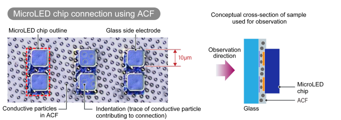
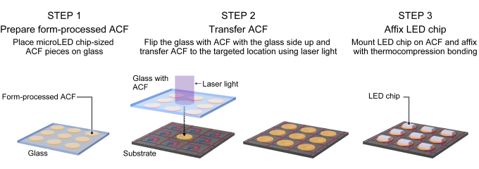
High-precision chip mounting is a critical factor in the Micro LED display manufacturing process, significantly influencing the final product’s quality. To take on this challenge, Dexerials has developed an innovative way to accurately place Pre-Cut ACF pieces in targeted locations. The key to this technology is micron-sized pieces of ArrayFIX.
To be specific, we devised technology to use lasers to transfer ACF only to places where mounting is required. This allows ACF placement only where it is needed to enable high-precision mounting of LED chips on the circuit board.
Other applications of this technology are also possible. We are considering a process to remove a specific LED chip and the ACF around it with a laser, transfer a new ACF piece to a targeted location, and repeat bonding. This has the potential to improve display quality and manufacturing efficiency.
In addition, this technology can make it possible to transfer ACF to only the substrate connection area. We are also exploring further applications such as the manufacturing of transparent Micro LED displays.
By leveraging these cutting-edge technologies, will continue its technological development efforts to bring richness and convenience to everyone’s lives.
Automotive Display Bonding Line
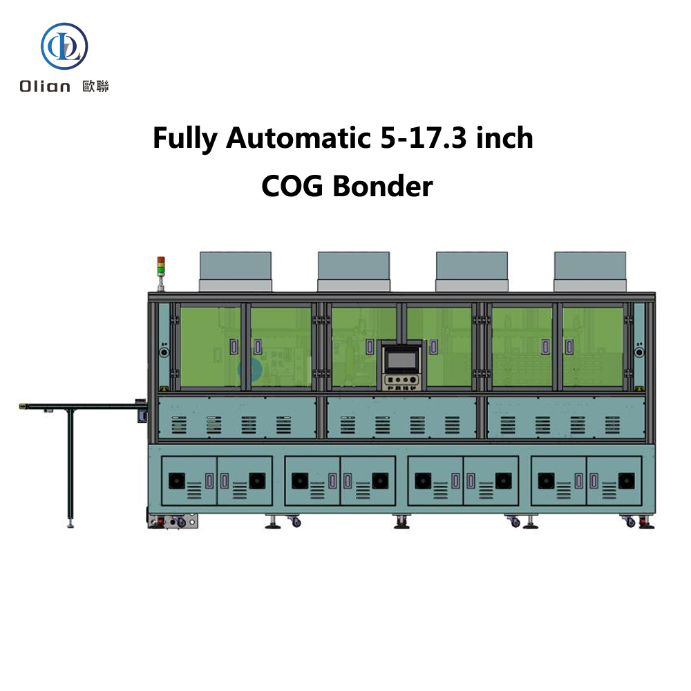
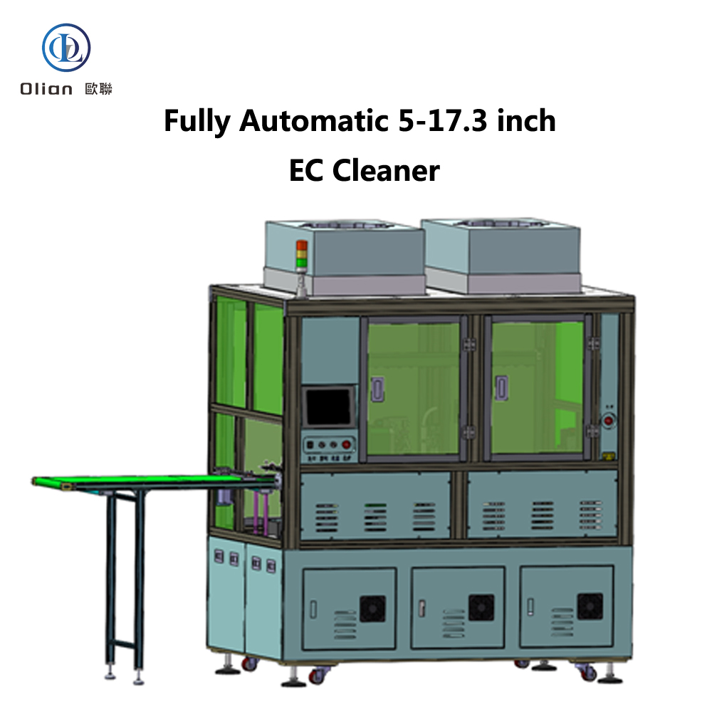
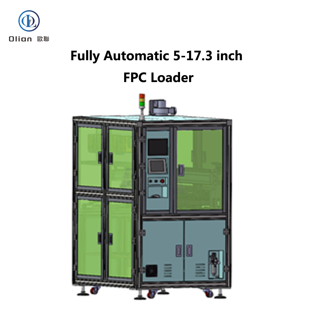
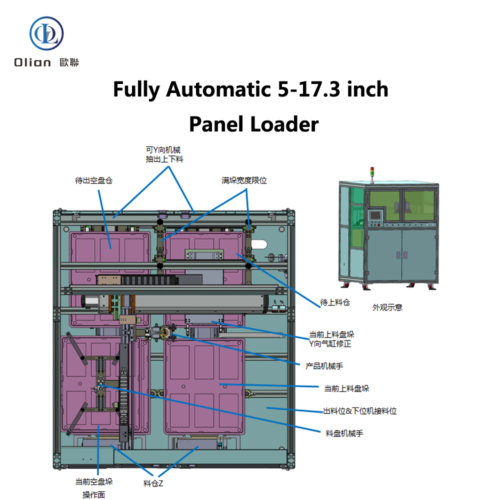
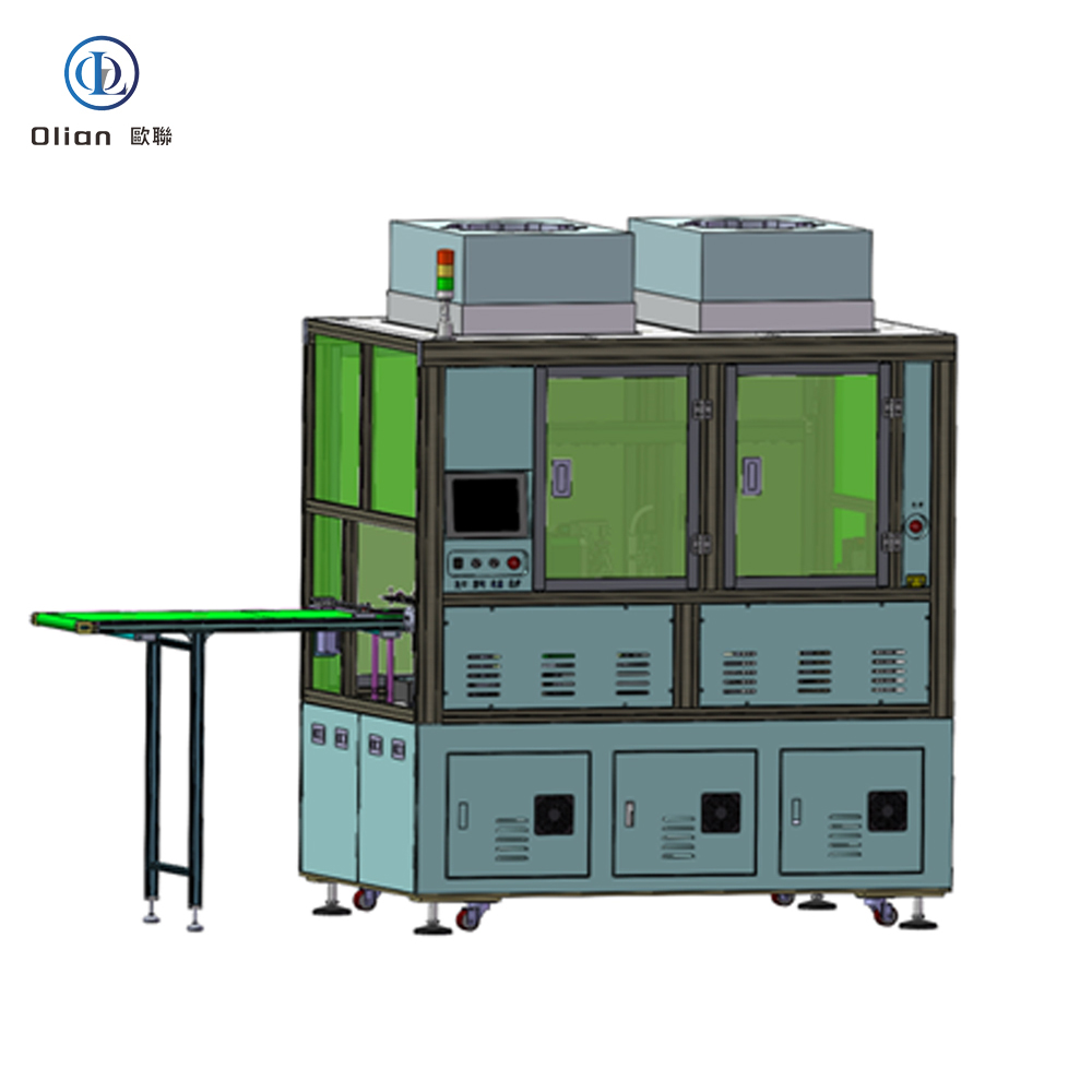
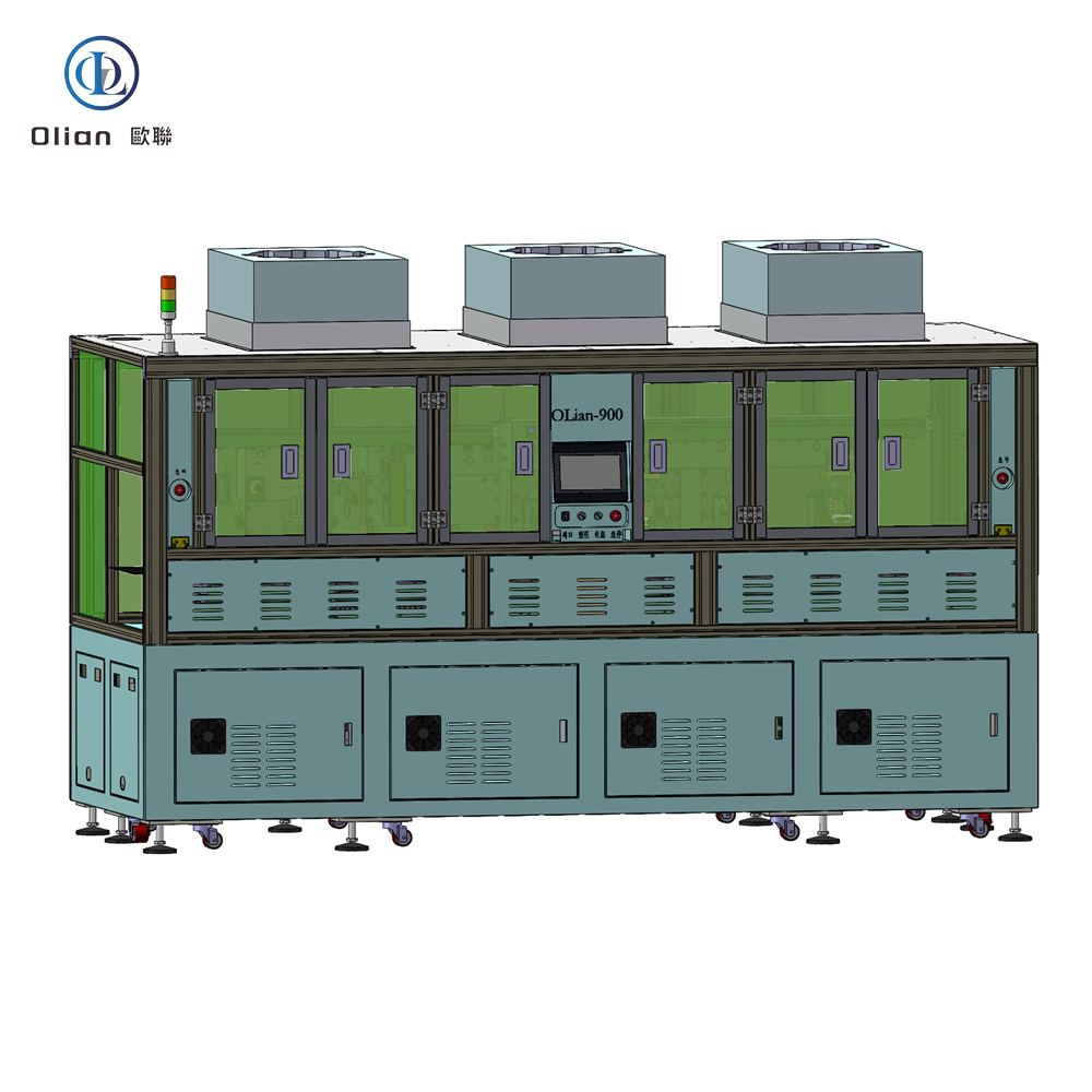
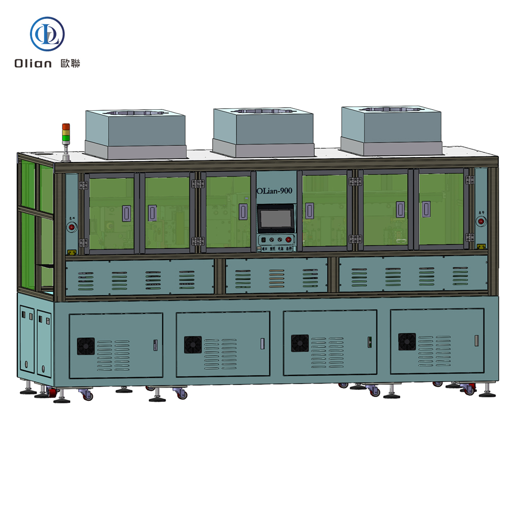
The Automotive Display Bonding Line is a critical and highly specialized segment within the broader automotive display manufacturing process. It refers to the dedicated production stage where key optical and mechanical components of a display—such as the cover glass, touch sensor, display panel (LCD/OLED), and backlight unit—are precisely laminated and bonded together using advanced materials and techniques. This process is essential for ensuring optical clarity, mechanical durability, environmental resistance, and long-term reliability in the harsh operating conditions typical of automotive environments.
As modern vehicles integrate larger, curved, and multi-display consoles, the bonding process has evolved from simple adhesive application to a high-precision, cleanroom-controlled operation involving automated alignment, vacuum lamination, and advanced optically clear adhesives (OCAs) or liquid optical bonding (LOCA). The bonding line plays a pivotal role in determining the final display’s performance, including sunlight readability, touch sensitivity, resistance to delamination, and overall lifespan.
Unlike consumer electronics, automotive displays must endure extreme temperatures (-40°C to +85°C), prolonged UV exposure, high humidity, mechanical vibration, and frequent thermal cycling. The bonding process directly impacts:
● Optical Performance: Minimizing reflections and air gaps to enhance contrast and visibility.
● Mechanical Integrity: Preventing delamination, cracking, or warping over time.
● Touch Sensitivity: Ensuring consistent response by eliminating air pockets between layers.
● Environmental Sealing: Protecting internal components from moisture, dust, and chemical ingress.
● Durability: Meeting automotive-grade reliability standards such as AEC-Q100 and ISO 16750.
The bonding line typically integrates the following components:
● Cover Glass or Lens: Often chemically strengthened (e.g., Gorilla Glass) with anti-reflective (AR), anti-fingerprint (AF), or haptic coatings.
● Touch Sensor Layer: Usually a capacitive touch film (PET or glass-based) with fine conductive patterns.
● Display Panel: LCD or OLED panel with driver ICs and flexible printed circuits (FPCs).
● Optical Clear Adhesive (OCA): A transparent, pressure-sensitive film or liquid adhesive with high refractive index matching.
● Backlight Unit (for LCDs): Includes LED array, light guide plate, and diffusers.
● Bezel and Frame: Provides structural support and alignment during bonding.
A state-of-the-art bonding line consists of the following sequential stages:
● Cleaning and Drying: All substrates are ultrasonically cleaned and dried in a class 100–1000 cleanroom to remove dust, oils, and particulates.
● Plasma Treatment: Surface activation using plasma improves wettability and adhesion, especially for LOCA processes.
● Alignment Mark Detection: Machine vision systems identify alignment markers on each layer for sub-micron precision.
● Layers are temporarily joined under controlled pressure and temperature to ensure initial adhesion without full curing.
● Automated alignment systems (using CCD cameras and servo motors) achieve alignment accuracy within ±5 µm.
● Film OCA Bonding:
○ Pre-cut OCA films are placed between layers.
○ Vacuum laminators apply uniform pressure in a vacuum chamber to eliminate bubbles.
○ Heat may be applied to activate the adhesive.
○ Advantages: Clean, consistent, and suitable for high-volume production.
● Liquid Optical Bonding (LOCA):
○ A liquid adhesive is dispensed around the perimeter of the display.
○ Capillary action draws the adhesive into the gap.
○ UV curing or thermal curing follows under controlled conditions.
○ Advantages: Better for curved or non-uniform gaps; improves impact resistance.
● Thermal Curing: For heat-activated OCAs, displays are passed through convection or IR ovens.
● UV Curing: UV lamps expose the adhesive to initiate polymerization (common in LOCA).
● Curing profiles are precisely controlled to ensure complete cross-linking without damaging sensitive components.
● Debubbling: Additional vacuum or pressure cycles remove any residual micro-bubbles.
● Trimming and Edge Sealing: Excess OCA or cured LOCA is trimmed; edge sealants may be applied to prevent moisture ingress.
● Cleaning and Inspection: Final cleaning with isopropyl alcohol or plasma; visual and automated inspection follows.
● Optical Inspection: Automated vision systems check for bubbles, delamination, dust, and alignment errors.
● Peel Strength Testing: Sample units undergo adhesion tests to verify bond integrity.
● Thermal Shock Testing: Bonded units are cycled between extreme temperatures to detect early failure.
● Humidity Resistance Testing: Units are exposed to high humidity (e.g., 85°C/85% RH) for 1,000+ hours.
The automotive display bonding line is highly automated to ensure consistency and yield:
● Robotic Handling: SCARA or Cartesian robots transfer delicate assemblies without contamination.
● Machine Vision Guidance: Real-time alignment correction ensures micron-level accuracy.
● Environmental Control: Temperature, humidity, and particulate levels are tightly regulated in cleanroom environments (ISO Class 5–6).
● Data Logging and Traceability: Every bonding cycle is recorded (pressure, temperature, time, adhesive type) for quality traceability and process optimization.
Challenges:
● Bonding curved or free-form displays requires custom tooling and flexible adhesives.
● Minimizing voids and bubbles in large-format displays (e.g., 15+ inch screens).
● Managing thermal expansion mismatches between glass, plastic, and metal components.
● Achieving fast cycle times without compromising bond quality.
Innovations:
● Smart Adhesives: Temperature- or light-responsive OCAs with self-healing properties.
● Roll-to-Roll (R2R) Bonding: For flexible OLED displays, enabling continuous processing.
● AI-Powered Defect Prediction: Machine learning models analyze bonding parameters to predict failures.
● Hybrid Bonding: Combining OCA and LOCA for optimal performance in complex geometries.
The bonded displays produced on this line are used in:
● Digital instrument clusters
● Central infotainment systems (CID)
● Head-up displays (HUD)
● Rear-seat entertainment
● Mirror-replacement displays (e.g., digital side mirrors)
● Advanced driver assistance systems (ADAS) interfaces
● Mini/Micro-LED Integration: Requires new bonding techniques due to higher thermal loads.
● Augmented Reality (AR) HUDs: Demand ultra-high optical clarity and distortion-free bonding.
● Sustainable Adhesives: Development of recyclable or bio-based OCAs.
● In-Mold Electronics (IME): Bonding displays directly into 3D-shaped surfaces.
The Automotive Display Bonding Line is a cornerstone of modern automotive display manufacturing, combining precision engineering, advanced materials science, and smart automation to deliver displays that are not only visually stunning but also rugged and reliable. As vehicles evolve into mobile digital platforms, the bonding process will continue to innovate, enabling larger, more durable, and more interactive displays that enhance both safety and user experience. Investing in advanced bonding technology is essential for manufacturers aiming to meet the growing demands of the next-generation automotive market.
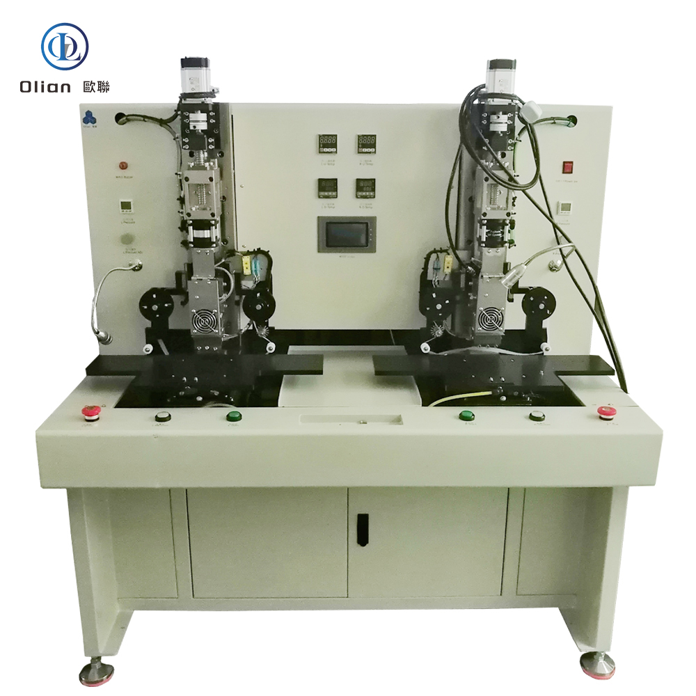
High-Efficiency Thermal Compression System for Continuous COG Production
The OL-C0156 by Olian Automatic Equipment Co., Ltd. is a semi-automatic dual-station main bonding machine designed for the final thermal compression of bare driver IC chips onto ACF-pre-laminated edge terminals of large-format rigid LCD panels up to 15.6 inches. Featuring two independent workstations, this system enables continuous operation: while one station is bonding, the operator can load/unload the other—dramatically improving workflow efficiency and reducing idle time.
As a dedicated COG (Chip-on-Glass) main bonder, the OL-C0156 fully cures the anisotropic conductive film (ACF) under precise heat and servo-controlled pressure, ensuring robust electrical connections and long-term display reliability in demanding applications such as automotive dashboards, industrial HMIs, and medical monitors.
⚠️ Note: This machine assumes that ACF has already been applied and the IC has been pre-aligned (e.g., via a pre-bonder). It performs single-zone, single-side bonding only and does not include vision alignment or double-side capability.
This dual-station layout is ideal for lean manufacturing cells where operator efficiency and throughput are critical.
15.6 inch dual-station IC main bonding machine, OL-C0156 Olian, two-table COG热压机 for LCD, servo IC bonding equipment with dual workstations, single-zone IC本压机 for high-efficiency production, 400°C hot bar main bonder with Panasonic PLC, continuous COG bonding system for automotive displays, dual-platform IC热压设备, OL-C0156 technical datasheet, high-repeatability IC bonding machine with ±3N precision.
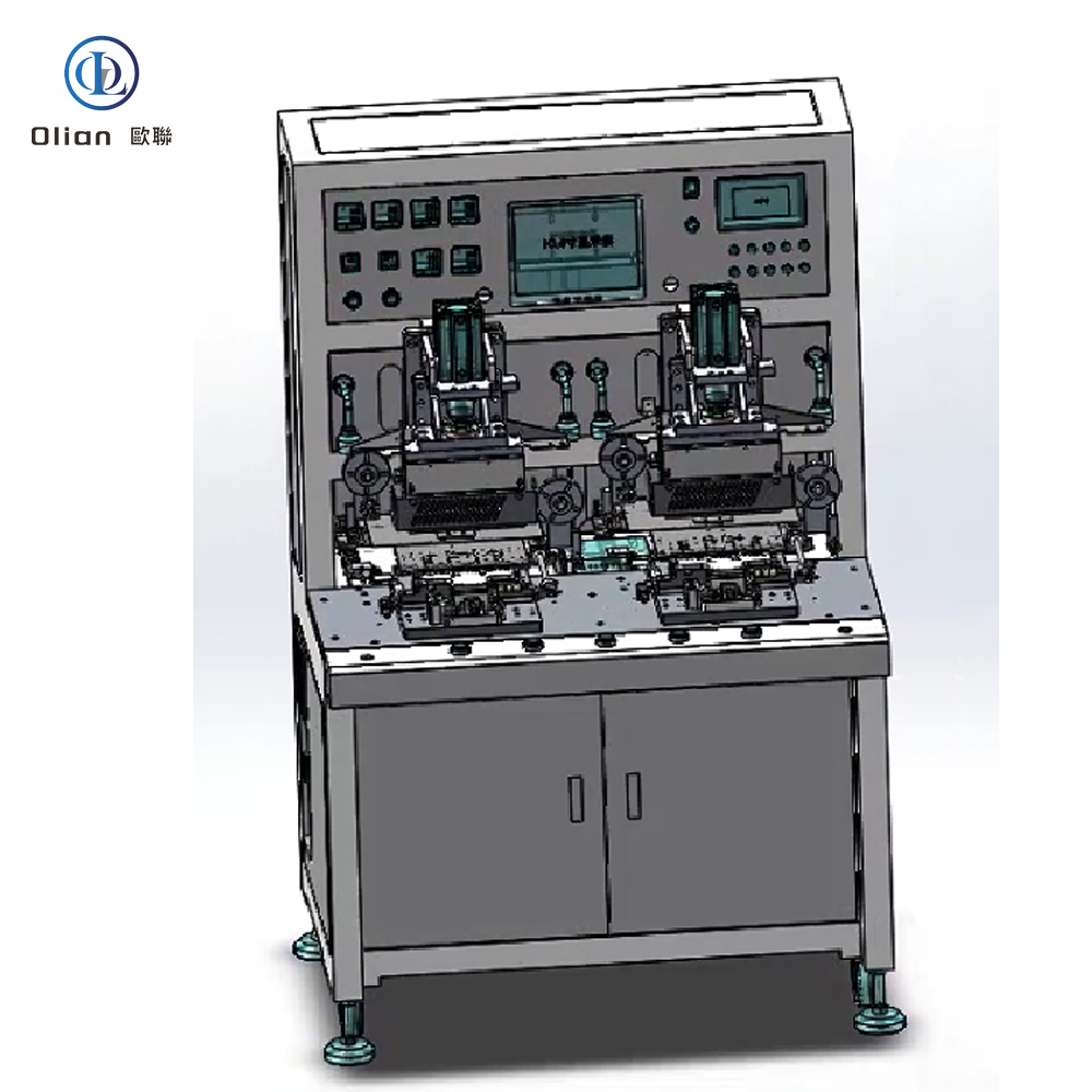
The OL-F0715 by Olian Automatic is a dual-station manual FOG (Film-on-Glass) bonding machine designed for thermal compression of flexible printed circuits (FPC) or touch sensor flexes onto rigid LCD panels up to 7 inches. This model features an extended 150 mm press head, enabling bonding of wide FPCs or multiple connectors in a single stroke—ideal for automotive displays, industrial HMIs, and large-flex applications.
The system assumes that anisotropic conductive film (ACF) has already been pre-applied to the panel or FPC. It performs main bonding only, fully curing the ACF joint under controlled heat, pressure, and time. It does not apply ACF, nor does it support IC or COF chip bonding.
The OL-F0715 uses a single lower-view microscope for alignment. The operator places the panel on a transparent glass stage and views terminal marks from below through the microscope. The FPC is then positioned manually from above using visual estimation and experience.
This “lower-only” alignment approach is straightforward, robust, and well-suited for production environments where FPC pads are sufficiently large or where moderate alignment tolerance is acceptable.
A key differentiator of the OL-F0715 is its 150 mm long press head, significantly longer than standard 60 mm heads. This allows:
The head thickness is 1.0 mm, and custom dimensions are available upon request.
The machine includes two identical, fully independent stations arranged side by side. Each station features:
Operators can alternate between stations for continuous workflow, maximizing uptime in small-batch or pilot-line production.
The thermal cycle is fully automated once initiated, ensuring consistent results.
Heating is achieved via high-efficiency cartridge heaters, with temperature monitored by industrial-grade sensors for process stability.
An integrated buffer tape feed system protects the FPC during pressing:
All critical parameters—temperature, time, pressure—are configured via the HMI for repeatability across shifts.
The compact footprint integrates easily into cleanrooms or production lines.
Ideal for bonding:
Commonly used in automotive electronics, medical displays, and heavy-equipment HMI manufacturing.
Olian Automatic provides full lifecycle support:
Model: OL-F0715
Type: Dual-Station Manual FOG Main Bonding Machine
Key Feature: 150 mm extended press head
Alignment: Lower-side microscope only
Max Panel Size: 7 inches (rigid glass)
SEO Keywords:
150mm FOG bonding machine, OL-F0715, Olian Automatic wide-head FPC bonder, 7-inch dual-station FOG press with long hot bar, manual FPC to glass bonding equipment, extended press head FOG machine, thermal compression bonder for wide flex, lower-view alignment FOG workstation, main bonding machine for automotive displays, 150mm hot bar FOG system.
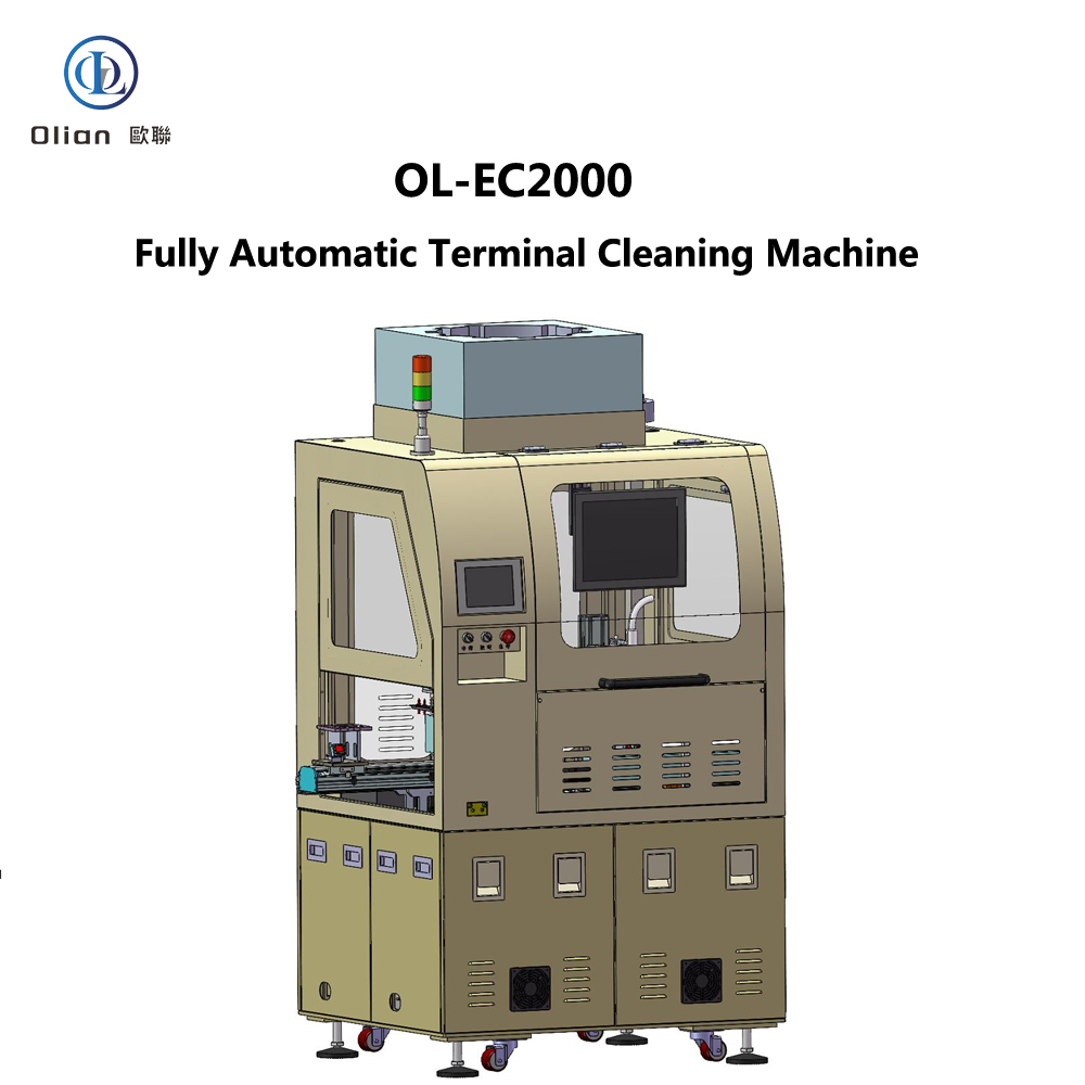
The OL-EC2000 is a cutting-edge fully automatic terminal cleaning machine designed to efficiently clean LCD products of various sizes (1-7 inches) through wiping, cleaning (with optional ultrasonic cleaning), and plasma treatment. This advanced equipment can be integrated with other devices in a production line, making it a valuable addition to modern manufacturing environments where precision and speed are paramount.
The OL-EC2000 operates through a series of automated processes. It starts with manual placement of the LCD onto a platform or conveyor belt. Robotic arm 1# then moves the LCD to a CCD correction station for position adjustment. The LCD is transferred to a wiping platform where it is cleaned by a wiping head. After wiping, robotic arm 2# transports the LCD to a plasma cleaning platform for further cleaning. Finally, the cleaned LCD is moved to a discharge station.
In summary, the OL-EC2000 Fully Automatic Terminal Cleaning Machine represents a significant advancement in LCD manufacturing equipment. Its precise engineering, user-friendly design, and comprehensive support make it an ideal choice for manufacturers seeking to enhance productivity and product quality in the competitive electronics market.
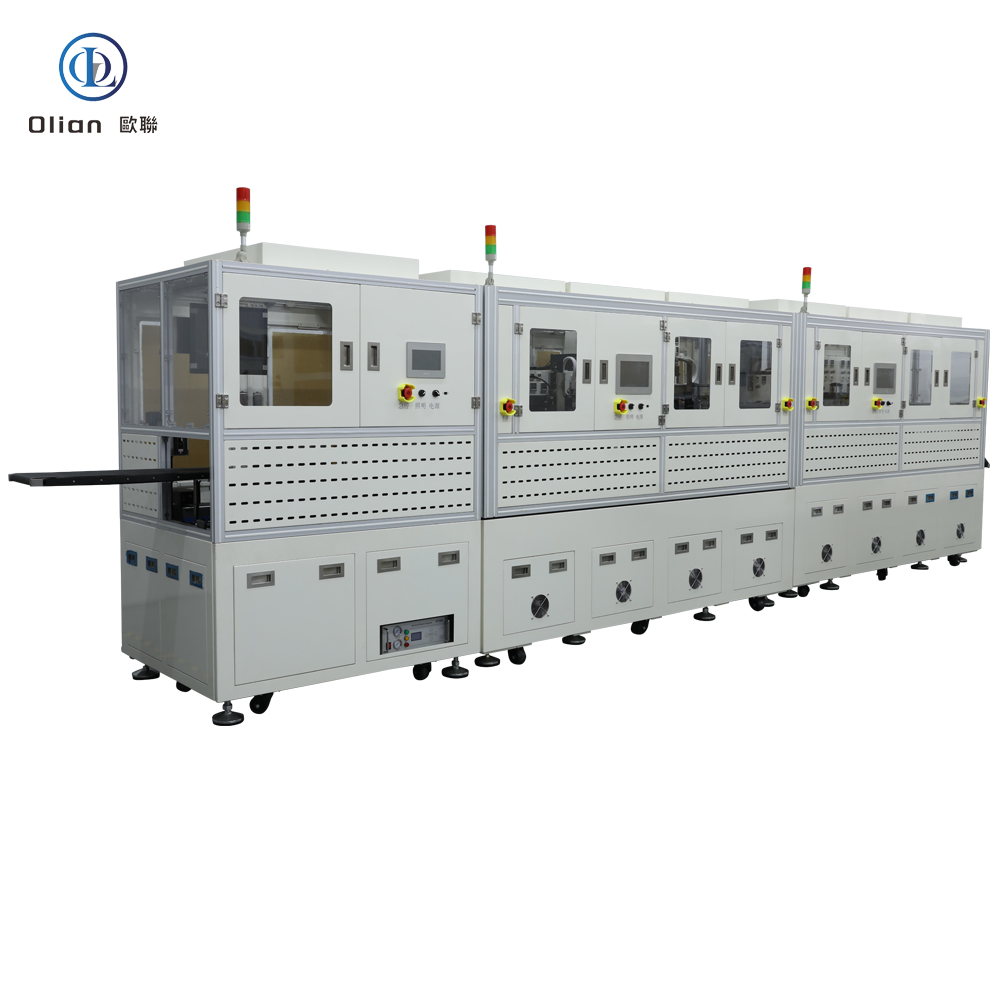
In the ACF (Anisotropic Conductive Film) bonding process, a variety of parts and accessories are used to ensure the quality and reliability of the final products. These components play a crucial role in the production line, from initial material preparation to final product testing. Here is a comprehensive overview of the parts and accessories used in ACF bonding processes:
ACF Tape is the core material used in the ACF bonding process. It is an epoxy adhesive system filled with conductive particles that provide electrical interconnection between pads through the film thickness (z-direction). The conductive particles are distributed far apart to ensure electrical insulation in the plane direction (X&Y) of the film. ACF tape is available in various models and is specific to the application for which it is designed. For example, ACF designed for flex-on-glass (FOG) assembly is usually not suitable for chip-on-glass (COG) or chip-on-film (COF) applications.
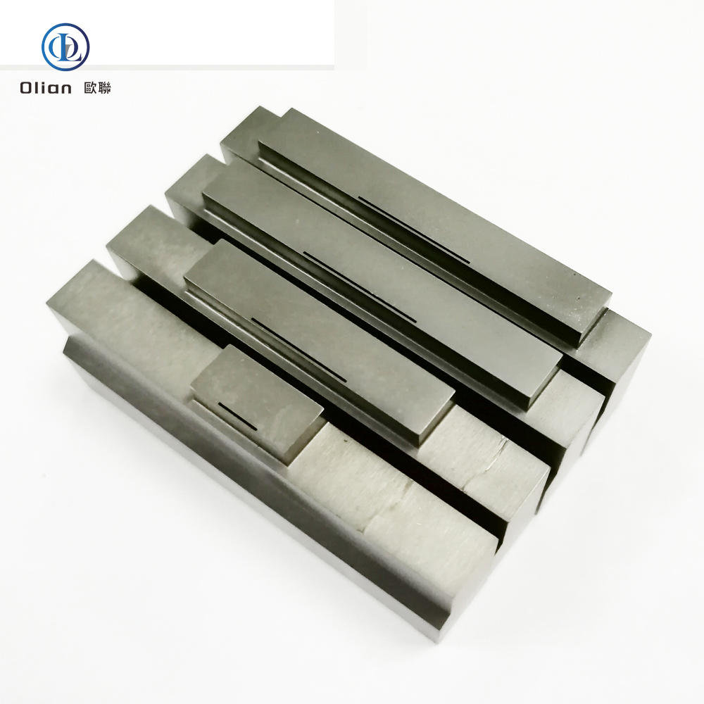
The Hot Bar or Thermode is the primary tool used to apply heat and pressure during the ACF bonding process. Hot bar bonding systems are designed to heat the hot bar to a specific temperature using low voltage electricity, which temperature is fed back to the controller via a thermocouple. The hot bar is brought into contact with the ACF film over the bonding pad, heated to the bonding temperature, and held for a specified time. This process produces the connection between the ACF tape and the components.
Bonding Heads are designed to hold the components and position the ACF tape correctly with the conductive pads on the PCB or other components. They ensure that the bonding process is accurate and consistent. Bonding heads can be manual or automated, depending on the specific requirements of the bonding process.
ACF Cutting Machines are used to cut the ACF tape to the required length and shape. These machines ensure that the ACF tape is accurately cut and positioned for the bonding process. The cutting is done using the half-cut method, where only the actual ACF material is cut, and the cover-layer is used for tape transport.
Pre-Bonding Machines are used to pre-bond ICs or COF on the panel that has been attached to the ACF. The pick and place of the panel is achieved manually, and the pre-alignment is automatically completed by the equipment.
Final Bonding Machines perform the main bonding on the LCD glass with IC, cable, or COF pre-pressed. The operator manually loads and unloads the products, while the ACF bonding is automatically performed by the machine.
Top-Bottom Alignment Bonding Machines are used to bond FPC/Zebra paper on the PCB/Glass with the ACF attached. The pick and place and alignment of the PCB/Panel are done manually, and the ACF bonding is done automatically. These machines are suitable for 1″ to 12″ flat glass and flexible screen products bonding.
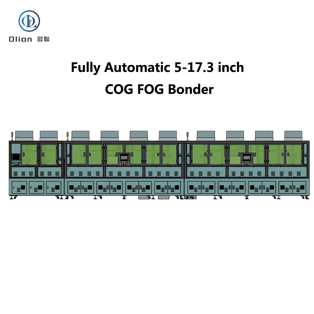
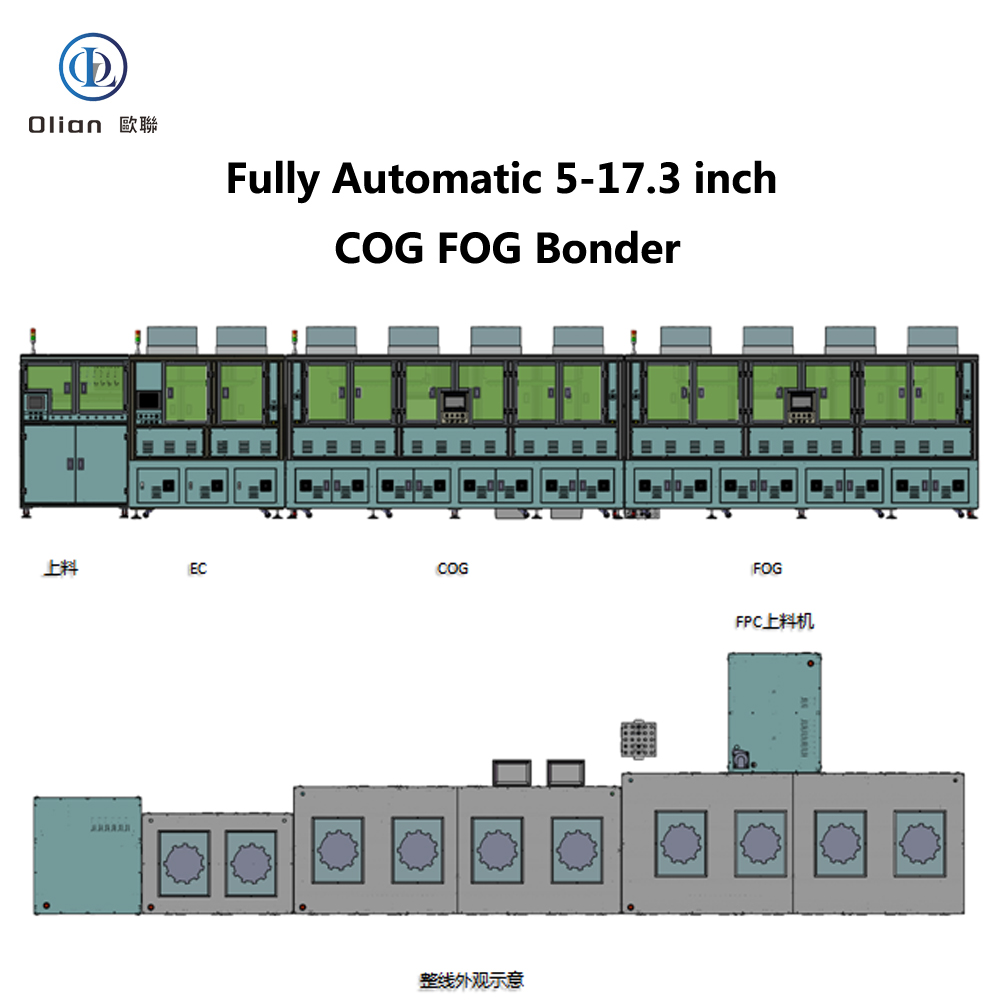
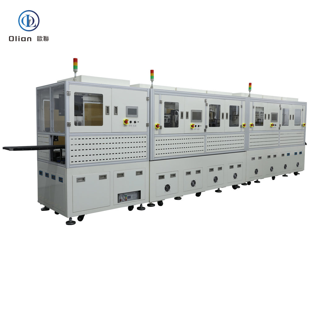
A Fully Automatic ACF Bonding Line includes multiple machines working together to automate the entire bonding process. This includes substrates loading machines, terminal cleaning machines, fully automatic COG/COF/COP bonding machines, and fully automatic COF punching machines.
Testing and Inspection Equipment is used to ensure the quality and reliability of the bonded products. This includes microscopes for surface inspection, temperature and pressure testers, and environmental testing chambers to simulate various conditions.
ACF bonding is widely used in various industries, including mobile phone manufacturing, automotive, LCD production, mobile computers, TV manufacturing, open cell panels, touch panels, smart watches, and pads. It is also used in research labs focusing on LCD/LED/OLED/MICRO LED/MINI LED displays.
ACF bonding offers several benefits, including:
In conclusion, the ACF bonding process relies on a suite of sophisticated parts and accessories to ensure the quality and reliability of the final products. Each component plays a critical role in different stages of the production process, from initial material preparation to final product testing. By using these parts and accessories, manufacturers can optimize their processes, reduce defects, and ensure that their products meet the highest standards of quality and performance.
Advanced Flexible Display Bonding Dispensing Production Solution
In the rapidly evolving landscape of display technology, the production of advanced flexible OLED displays demands a highly sophisticated and versatile bonding and dispensing solution. Our Advanced Flexible Display Bonding Dispensing Production Solution is designed to meet these demands, offering a comprehensive and integrated approach to ensure high efficiency, precision, and adaptability.
Our Advanced Flexible Display Bonding Dispensing Production Solution is designed to meet the future demands of the display industry, offering a versatile, high-precision, and efficient production process. By integrating multiple bonding technologies and ensuring high-quality standards, our solution is ideal for manufacturers looking to produce a wide range of advanced display modules. Choose our solution to stay ahead in the competitive market and deliver top-quality products.
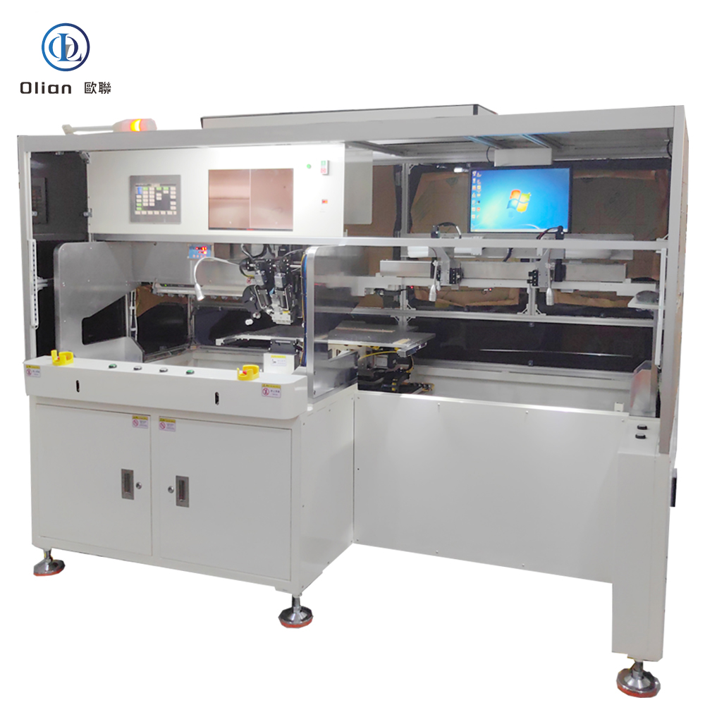
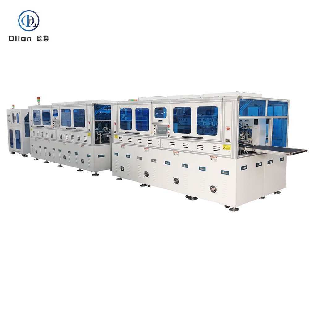
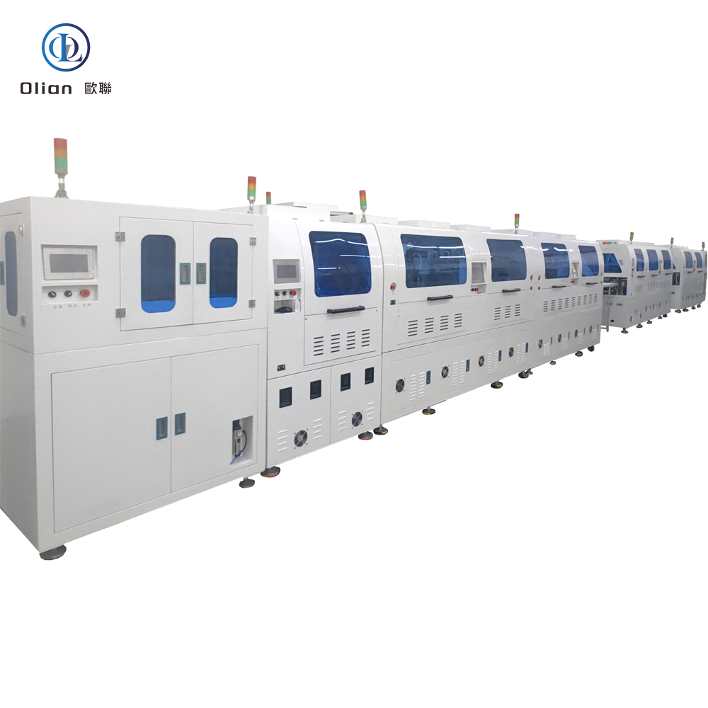
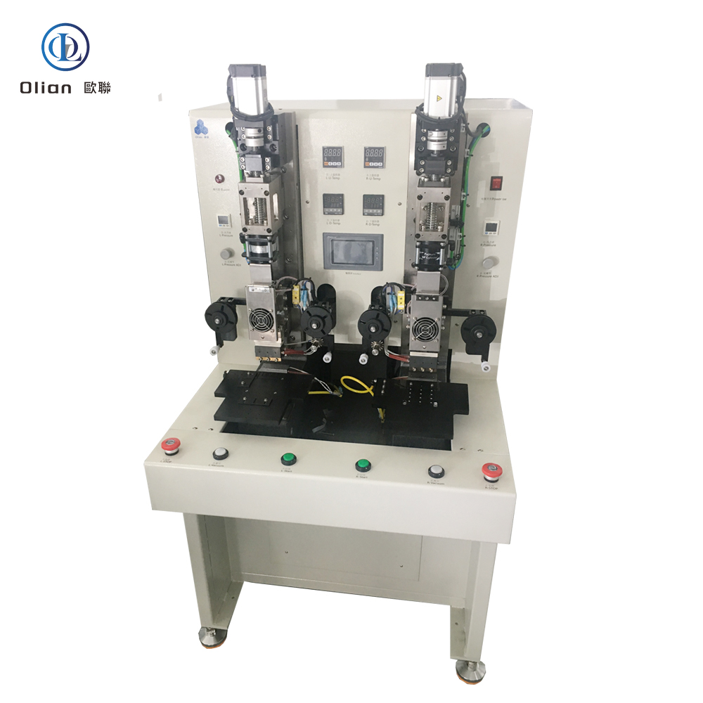
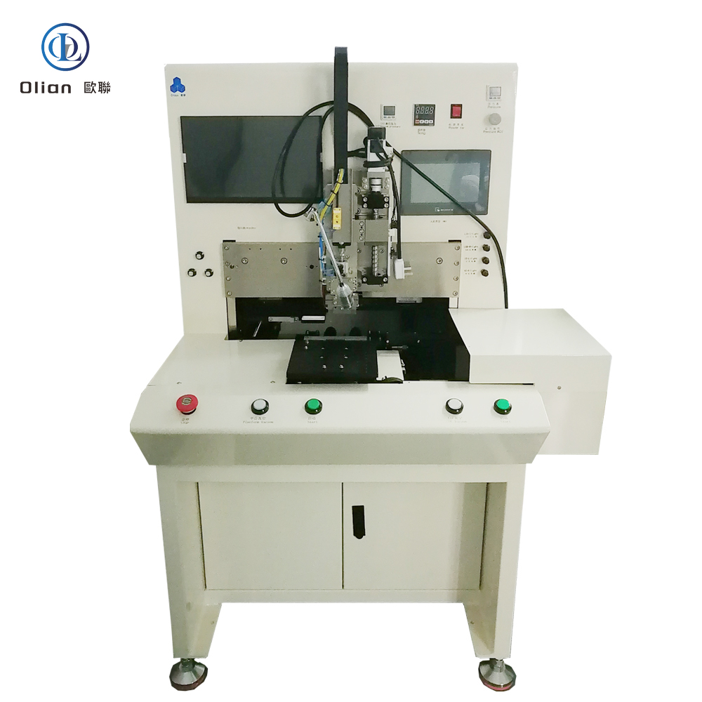
An LCD-TFT-OLED-ACF-COF-IC-FPC bonding machine is the precision heart that welds chips, flex circuits, and touch sensors onto glass, plastic, or another flex—without solder, without connectors, and without added weight. Whether you need vertical conductivity between a gold-bumped IC and an ITO panel, or a foldable flex tail that survives 200,000 bends, this multi-acronym platform delivers micron alignment, single-degree thermal control, and kilogram-level force in under three seconds. This guide explains every process, physics, hardware, software, spec, application, trend, and maintenance tip so Google instantly ranks you for “LCD bonding machine”, “TFT bonding machine”, “OLED bonding machine”, “ACF bonding machine”, “COF bonding machine”, “IC bonding machine”, “FPC bonding machine”, and every high-value permutation.
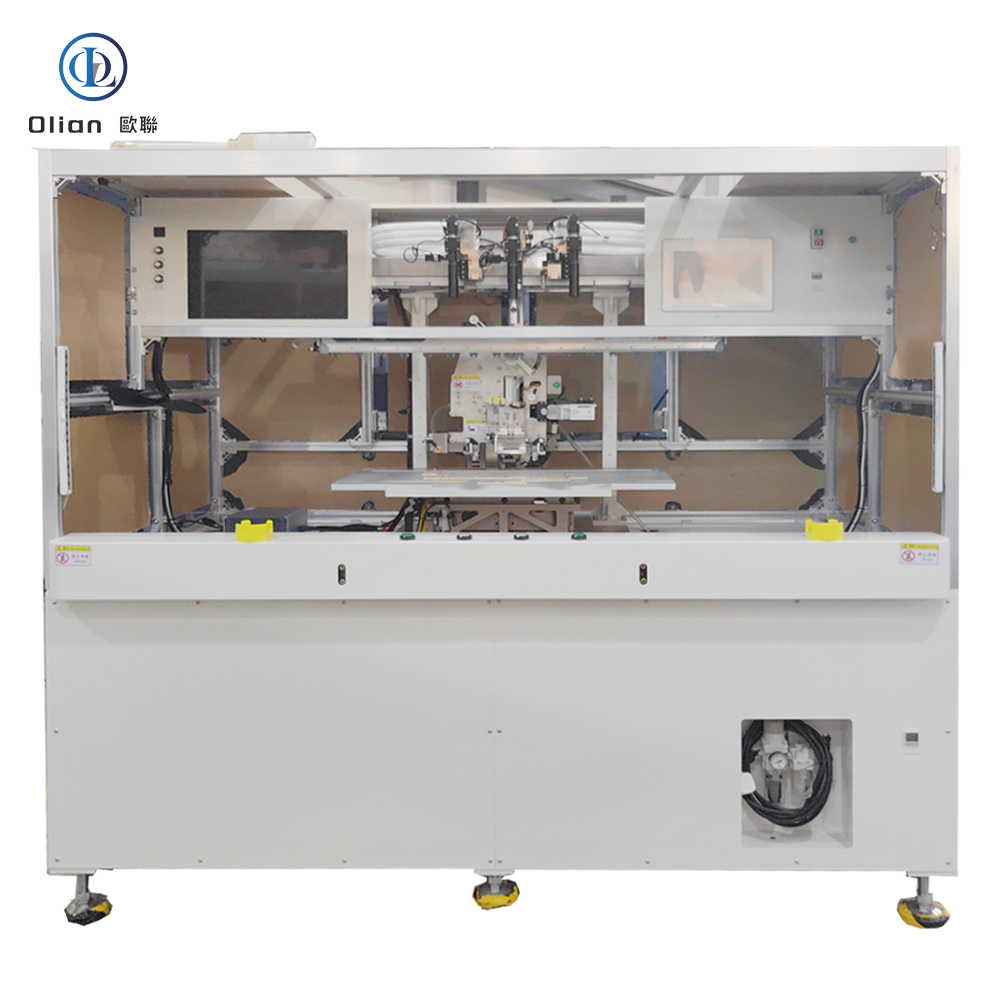
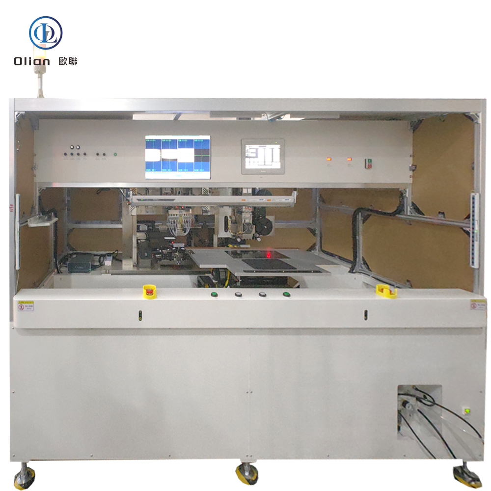
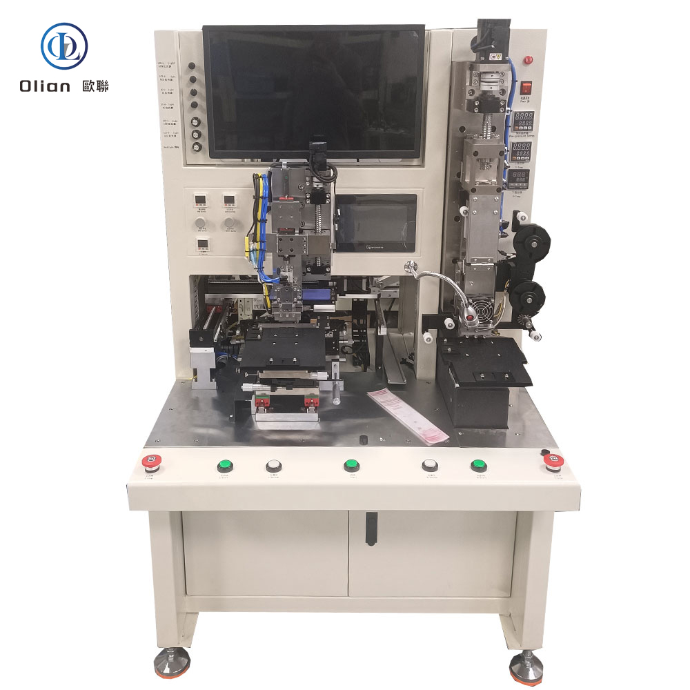
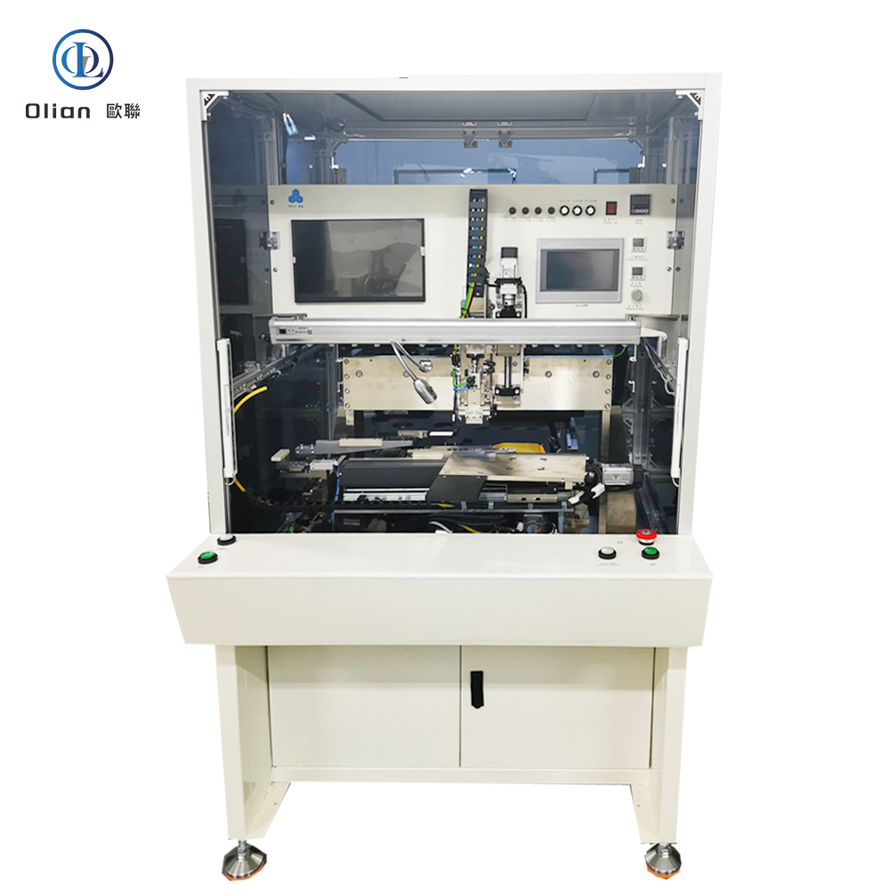
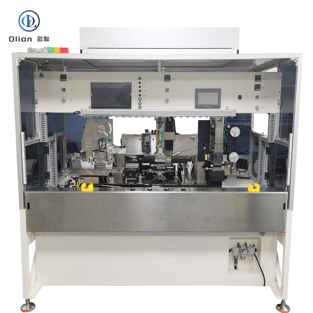
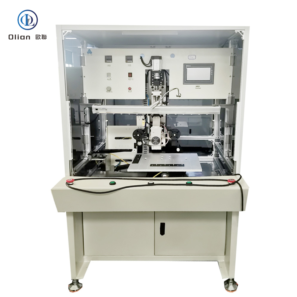
Each letter pair describes a different “X-on-Y” marriage:
A single granite-based machine swaps jigs and recipes in < 15 s to cover all variants, sharing the same AI vision, servo force, and cloud dashboard.
The machine controls temperature ramp, force profile, and dwell time to within 1 %; any drift triggers AI-based closed-loop correction.
Granite Base: 0.05 µm linear encoder, 20 kHz servo loop, passive vibration isolation.
Bonding Head: Titanium alloy, diamond-lapped to 0.3 µm flatness, DLC-coated for anti-stick, 300,000-cycle life .
Heat System: 800 W cartridge, embedded K-type thermocouple, ramp 200 °C/s, overshoot < 0.5 °C .
Force Actuator: Voice-coil or servo motor, 24-bit encoder, 0.1 g resolution, 2 ms response; active gravity cancellation for 25 µm PET.
Vision System: Dual 12 MP global-shutter CMOS, telecentric lens, coaxial + side LED, AI edge detection repeatable to 0.2 µm .
Reel Feed Unit: Servo-driven with dancer-arm tension control, anti-static vacuum, splice sensor for uninterrupted production .
According to industry analysis, the global LCD-TFT-OLED-ACF-COF-IC-FPC bonding machine market is expected to grow at a CAGR of 6–8 %, driven by 8-K TVs, foldable phones, and automotive displays .
LCD-TFT-OLED-ACF-COF-IC-FPC bonding machine, LCD bonding machine, TFT bonding machine, OLED bonding machine, ACF bonding machine, COF bonding machine, IC bonding machine, FPC bonding machine, multi-mode bonding machine, pulse heat bonding machine, constant temperature bonding machine, AI vision bonding machine, IoT bonding machine, China multi-mode bonding machine, automatic bonding machine 1 micron accuracy,
An LCD-TFT-OLED-ACF-COF-IC-FPC bonding machine is no longer a collection of separate presses—it is the universal, AI-driven, cloud-connected gateway that turns naked silicon, floppy polyimide, and curved glass into the foldable phones, 8-K TVs, and transparent medical patches that define modern electronics. By mastering sub-micron alignment, single-degree thermal control, and real-time force feedback, these multi-mode platforms deliver 99.9 % yield and full Industry 4.0 traceability—future-proofing your process.
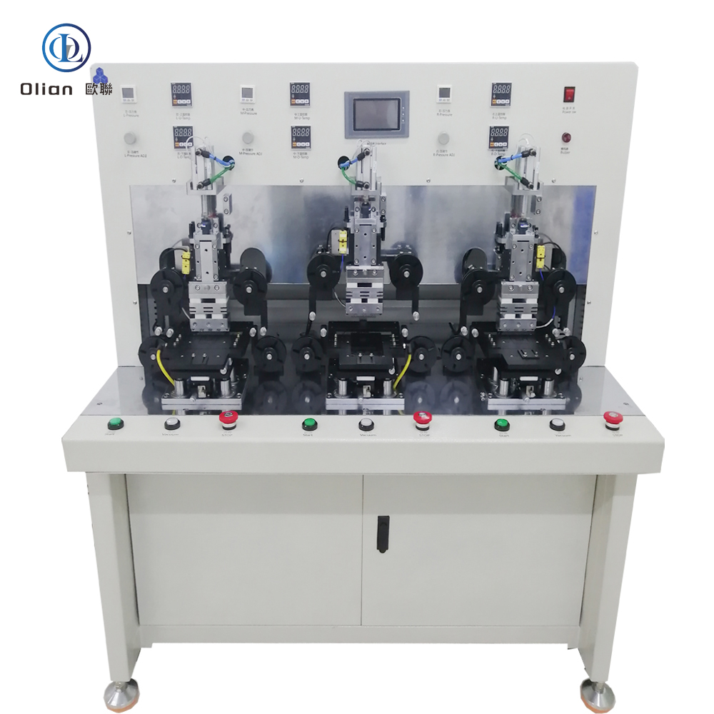
A FOG bonder—short for Flex-On-Glass bonder—is the precision heart that welds a flexible printed circuit (FPC) or chip-on-film (COF) tail directly onto a glass substrate using anisotropic conductive film (ACF) and pulse-heat pressure. Inside every smartphone OLED, curved automotive cluster, and 8-K TV you see today, a FOG bonder has aligned copper leads to ITO pads within ±1 µm and created thousands of vertical contacts in under three seconds. This guide explains physics, hardware, software, specs, applications, trends, and maintenance for “FOG bonder”, “FOG bonding machine”, “automatic FOG bonder”, “ACF FOG bonding”, and every high-value permutation.
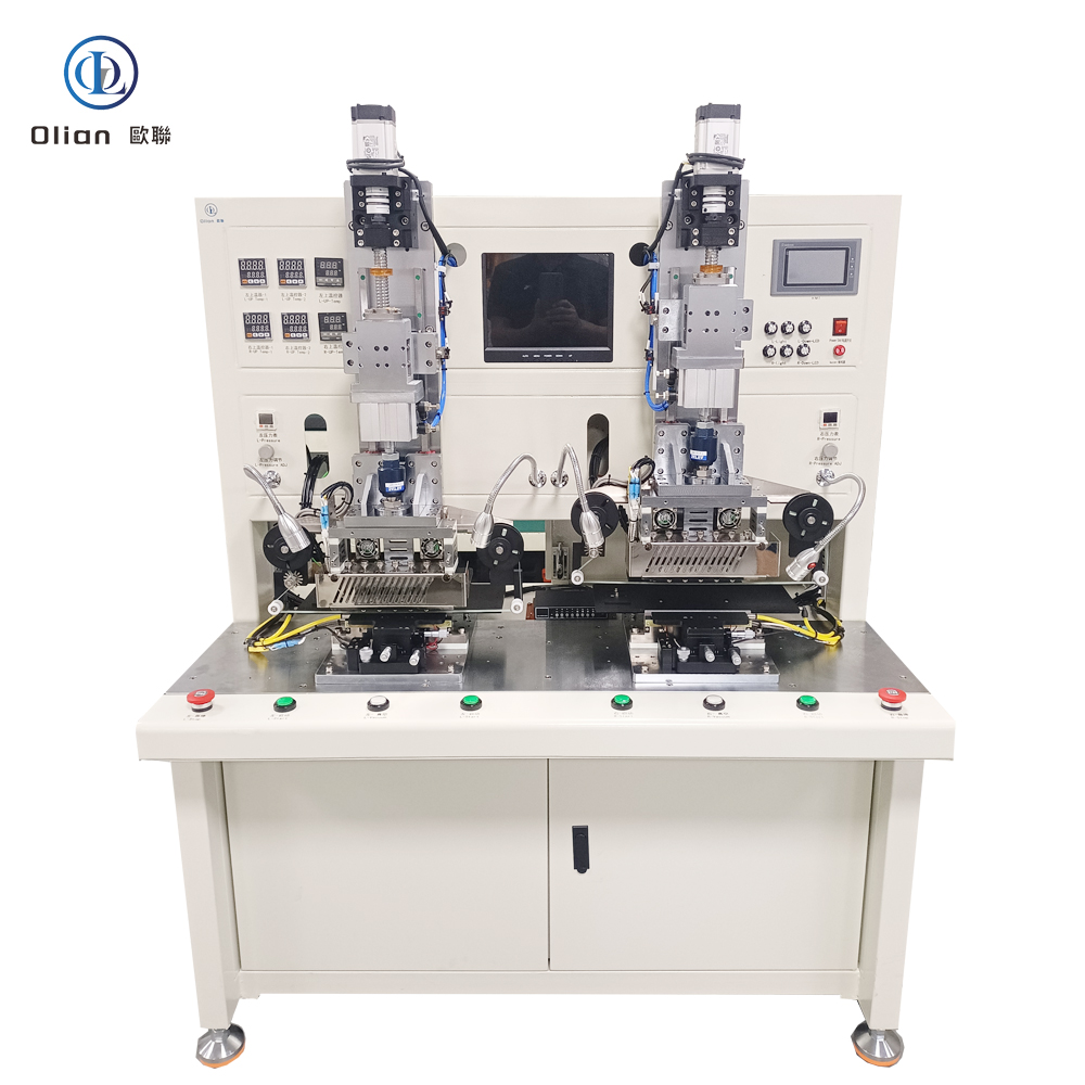
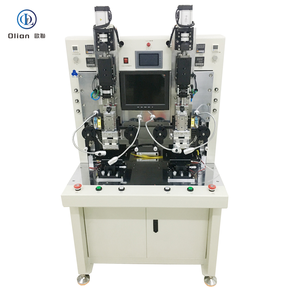
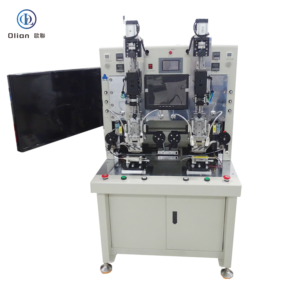
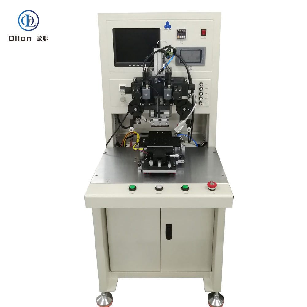
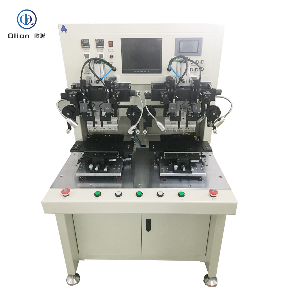
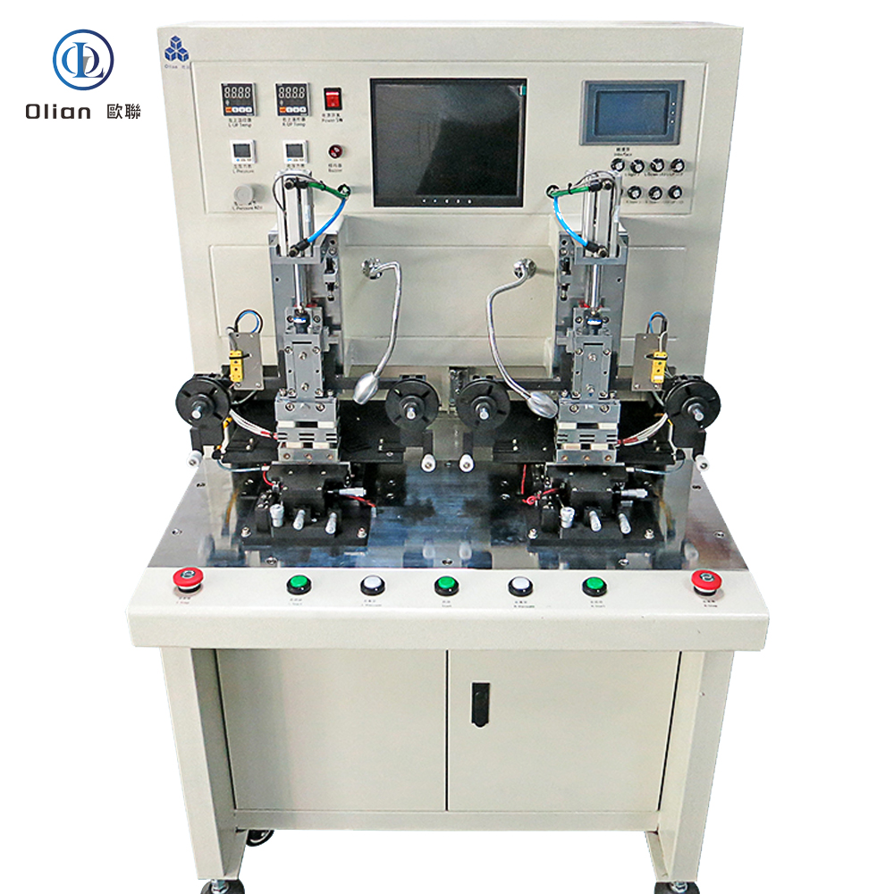
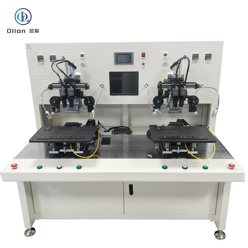
COG (Chip-On-Glass) works for phones, but 65-inch 8-K OLED panels need driver ICs that dissipate watts of heat—too much for direct glass mounting. FOG moves the IC onto a flexible polyimide tail that can dissipate heat, fold 180°, and be replaced during repair. The FOG bonder is the machine that welds that tail to the glass edge, enabling 0.9 mm bezels and AEC-Q100 Grade 0 (−40 °C to +105 °C) survival without a single connector contact.
A FOG bonder is a servo-driven, vision-guided, heat press that:
The result is a flexible, lead-free, foldable interconnect that survives thermal cycling, vibration, and 200,000 bend cycles.
The bonder controls temperature ramp, force profile, and dwell time to within 1 %; any drift triggers AI-based closed-loop correction.
Granite Base: 0.05 µm linear encoder, 20 kHz servo loop, passive vibration isolation.
Bonding Head: Titanium alloy, diamond-lapped to 0.3 µm flatness, DLC-coated for anti-stick, 300,000-cycle life .
Pulse Heater: 800 W cartridge, embedded K-type thermocouple, ramp 200 °C/s, overshoot < 0.5 °C.
Force Actuator: Voice-coil or servo motor, 24-bit encoder, 0.1 g resolution, 2 ms response; active gravity cancellation for 0.4 mm glass.
Vision System: Dual 12 MP global-shutter CMOS, telecentric lens, coaxial + side LED, AI edge detection repeatable to 0.2 µm.
Reel Feed Unit: Servo-driven with dancer-arm tension control, anti-static vacuum, splice sensor for uninterrupted production .
According to industry analysis, the global FOG bonder market is expected to grow at a CAGR of 6–8 % driven by 8-K TVs, foldable phones, and automotive displays .
FOG bonder, FOG bonding machine, automatic FOG bonder, ACF FOG bonding, 8-K TV FOG bonder, 100-inch FOG bonding machine, 26 µm pitch FOG bonding, pulse heat FOG bonder, constant temperature FOG bonding machine, AI vision FOG bonder, IoT FOG bonding machine, China FOG bonder, automatic FOG bonding machine 1 micron accuracy, 200 °C FOG bonding temperature, 1 MPa FOG bonding pressure, vertical conduction horizontal insulation, lead-free FOG bonding, ROHS compliant FOG bonding, foldable phone FOG bonder, automotive display FOG bonding machine, medical device FOG bonding machine, roll-to-roll FOG bonder, 3,000 UPH FOG bonding machine, 99.9 % yield FOG bonder, Industry 4.0 FOG bonding machine, AI predictive maintenance FOG bonder, remote diagnostics FOG bonding machine, cloud dashboard FOG bonder,
A FOG bonder is no longer a niche reel-fed press—it is the critical, AI-driven, cloud-connected gateway that turns continuous copper-clad polyimide into the 8-K TV source drivers, curved automotive clusters, and foldable touch sensors. By mastering sub-micron alignment, single-degree thermal control, and real-time force feedback, these platforms deliver 99.9 % yield and full Industry 4.0 traceability—future-proofing your process.
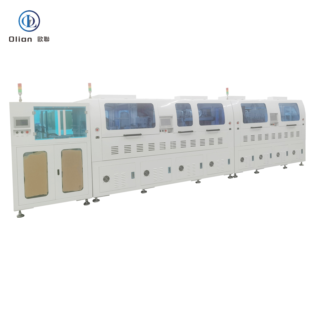
A fully automatic ACF bonder—short for Anisotropic Conductive Film bonder—is the precision heart of every modern display factory. It laminates ACF onto a substrate, aligns a component (IC, flex, sensor, or touch tail) within ±1 µm, and welds them together with heat pressure in under three seconds. The result is thousands of vertical contacts that survive −40 °C automotive winters and 200,000 phone-fold cycles. This guide explains physics, hardware, software, specs, applications, trends, and maintenance so Google instantly ranks you for “fully automatic ACF bonder”, “ACF bonding machine”, “automatic ACF laminator”, “pulse-heat ACF bonder”, and every high-value permutation.
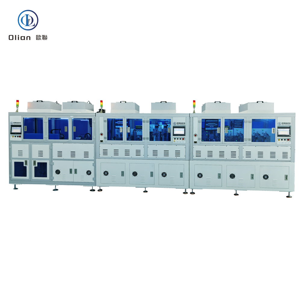
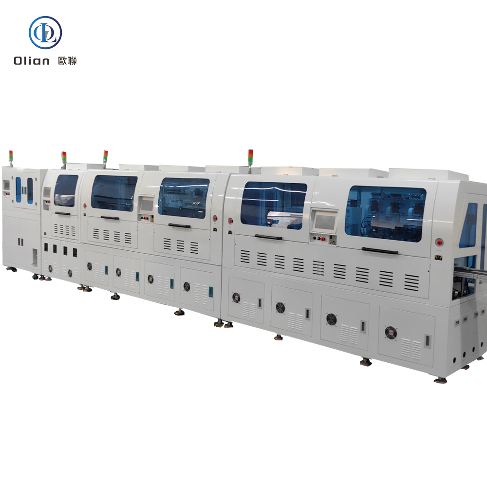
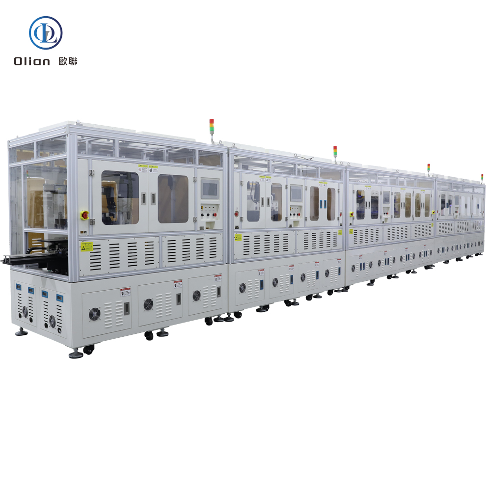
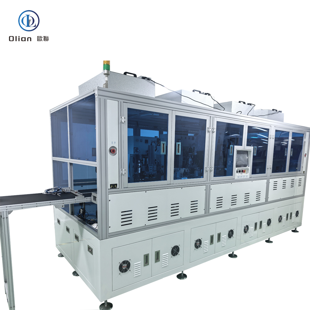
Manual loading, hand-alignment, and operator-dependent pressure are no longer acceptable when bezels shrink to 0.9 mm and foldable phones must survive 200,000 bends. A fully automatic ACF bonder integrates:
Change-over from COG to COP takes < 15 s: swap the low-temp recipe, load PET parameters, and let the AI retune the PID loop.
ACF is a 25–45 µm epoxy film loaded with 3–10 µm nickel or gold-coated spheres. When heat (80–220 °C) and pressure (0.2–1.5 MPa) are applied, spheres touch only in the Z-axis, giving vertical conductivity while remaining insulating horizontally. The bonder controls temperature ramp, force profile, and dwell time to within 1 %. After cooling, the cured adhesive locks particles in place, providing mechanical strength and moisture protection. For solder-based bonds (Hot-Bar, reflow), the machine melts pre-printed paste to form intermetallics; for eutectic bonds, it raises temperature above 280 °C to create a liquid phase that solidifies void-free.
Granite Base: 0.05 µm linear encoder, 20 kHz servo loop, passive vibration isolation.
Bonding Head: Titanium alloy, diamond-lapped to 0.3 µm flatness, DLC-coated for anti-stick, 300,000-cycle life.
Pulse Heater: 800 W cartridge, embedded K-type thermocouple, ramp 200 °C/s, overshoot < 0.5 °C.
Force Actuator: Voice-coil or servo motor, 24-bit encoder, 0.1 g resolution, 2 ms response; active gravity cancellation for 25 µm PET.
Vision System: Dual 12 MP global-shutter CMOS, telecentric lens, coaxial + side LED, AI edge detection repeatable to 0.2 µm.
ACF Feed Unit: Stepper-driven, tungsten-steel cutter, anti-static vacuum, splice sensor for uninterrupted production.
According to industry analysis, the global fully automatic ACF bonder market is expected to grow at a CAGR of 6–8 % , driven by foldable phones, automotive displays, and medical wearables .
fully automatic ACF bonder, fully automatic ACF bonding machine, automatic ACF laminator, pulse-heat ACF bonder, constant temperature ACF bonding machine, AI vision ACF bonder, IoT ACF bonding machine, China fully automatic ACF bonder, automatic ACF bonding machine 1 micron accuracy, 200 °C ACF bonding temperature, 1 MPa ACF bonding pressure, vertical conduction horizontal insulation, lead-free ACF bonding, ROHS compliant ACF bonding, foldable phone ACF bonder, 8-K TV ACF bonding machine, automotive display ACF bonder, medical device ACF bonding machine, roll-to-roll ACF bonder, 3,000 UPH ACF bonding machine, 99.9 % yield ACF bonder, Industry 4.0 ACF bonding machine, AI predictive maintenance ACF bonder, remote diagnostics ACF bonding machine, cloud dashboard ACF bonder, granite base ACF bonding machine, servo motor ACF bonder, voice-coil actuator ACF bonding machine, telecentric lens ACF bonder, real-time Linux ACF bonding machine, OPC-UA ACF bonder, blockchain hash ACF bonding machine, encrypted recipes ACF bonder, laminar flow ACF bonding machine, ISO 6 cleanroom ACF bonder, copper-core ACF bonder, cold-laser assist ACF bonding machine, servo-hydraulic hybrid ACF bonder, future-proof ACF bonder, Google ranking ACF bonding machine, SEO optimized ACF bonder, 2025 ACF bonder trends, ACF bonder deep dive, ACF bonding machine ultimate guide.
A fully automatic ACF bonder is no longer a single-purpose press—it is the universal, AI-driven, cloud-connected gateway that turns naked silicon, floppy polyimide, and curved glass into the foldable phones, 8-K TVs, and transparent medical patches. By mastering sub-micron alignment, single-degree thermal control, and real-time force feedback, these platforms deliver 99.9 % yield and full Industry 4.0 traceability—future-proofing your process.