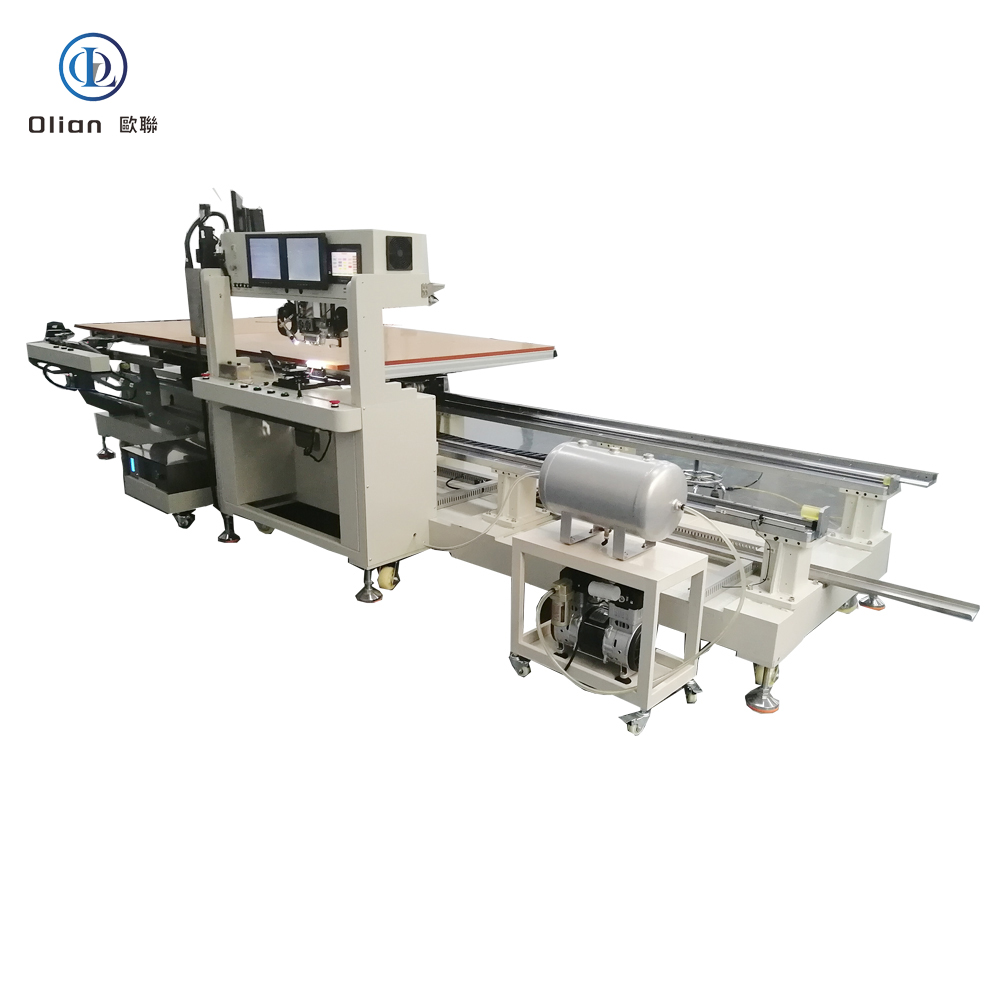
An OLB bonding machine is the hidden hero behind every large-screen TV, laptop and automotive display you see today. OLB—Outer Lead Bonding—is the final assembly step in which the “outer leads” of a TAB (Tape Automated Bonding) or COF (Chip-On-Film) package are attached to a glass panel or PCB so that signals from the driver IC can reach the outside world. The equipment that performs this micro-weld must deliver sub-micron alignment, single-degree thermal control and kilogram-level force accuracy—all in under three seconds. This article explains every angle of the technology for “OLB bonding machine”, “OLB bonder”, “outer lead bonding equipment”, “TAB OLB bonding”, “COF OLB bonding”, “LCD OLB repair machine” and dozens more high-value keywords.
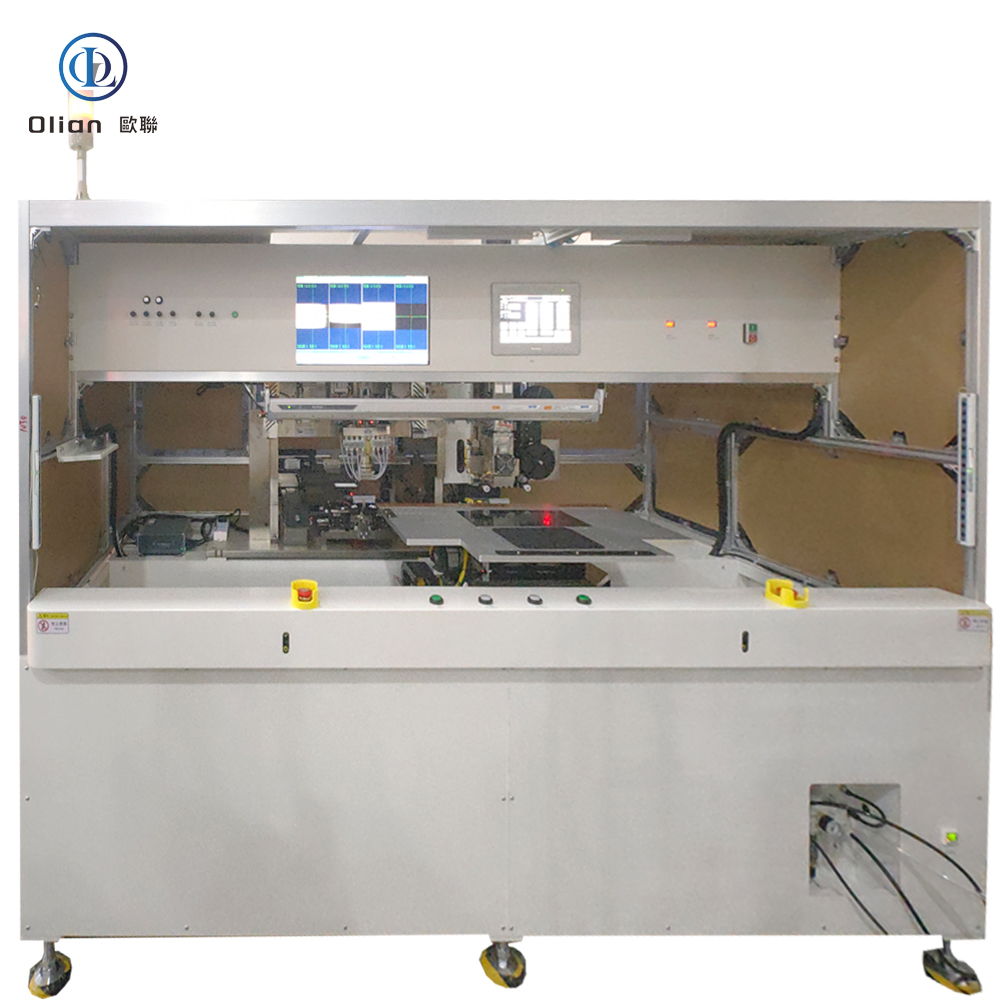
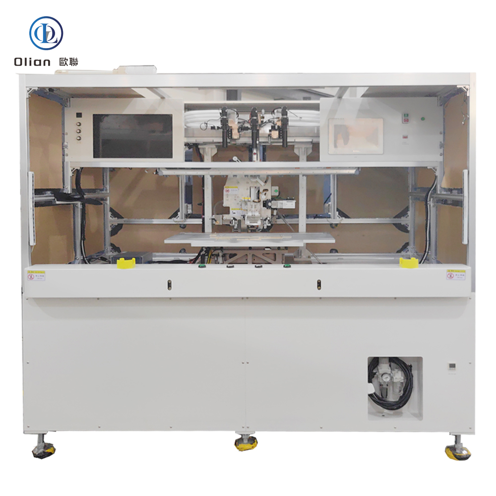
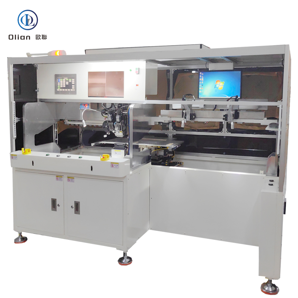

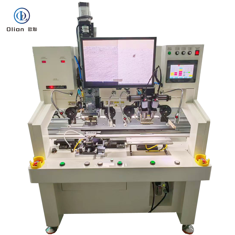
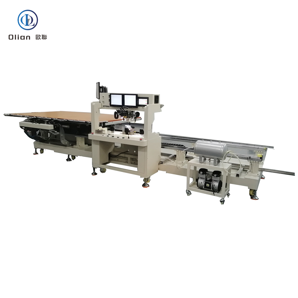

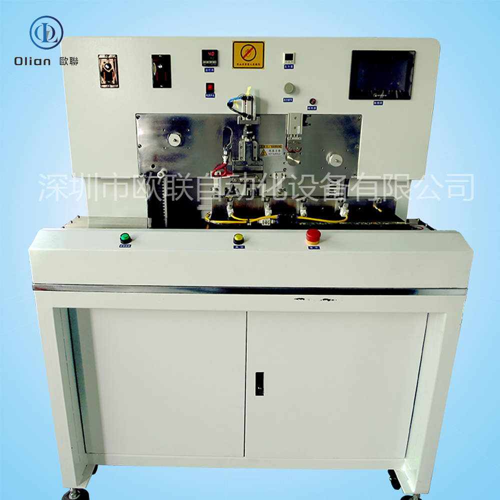
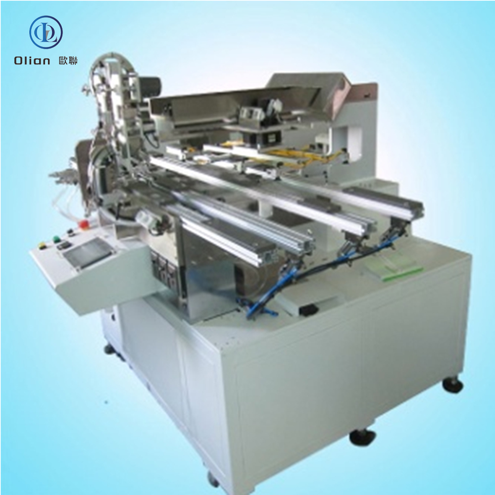
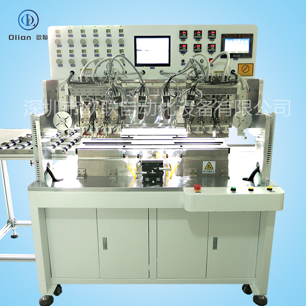
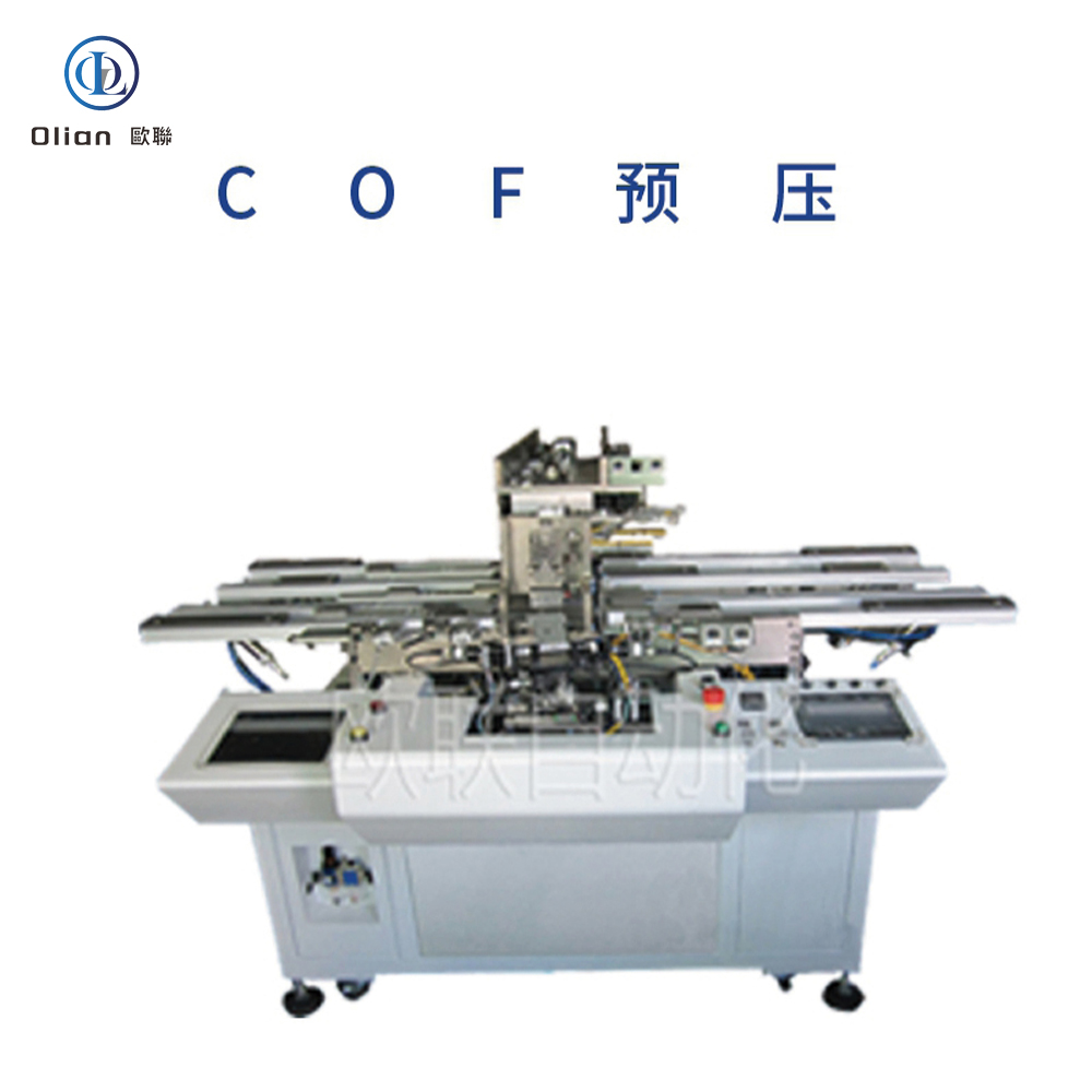
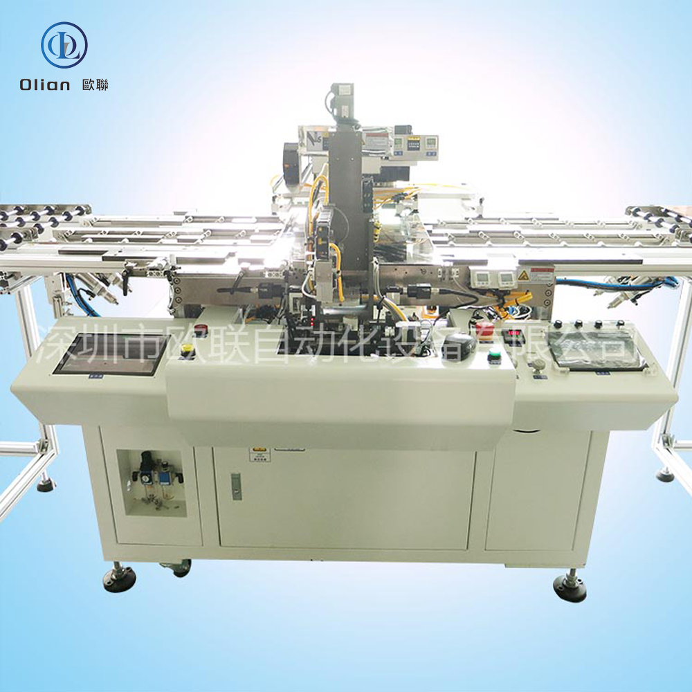

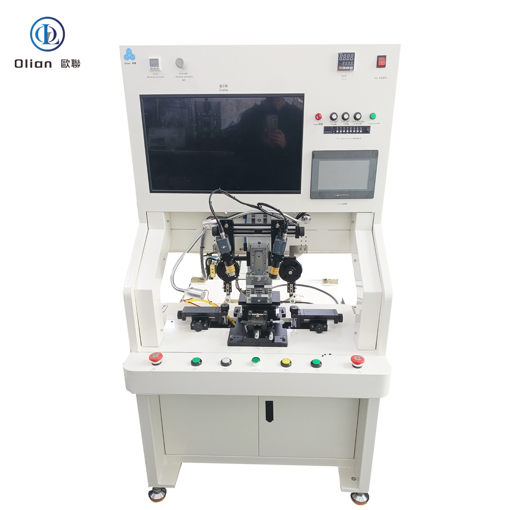
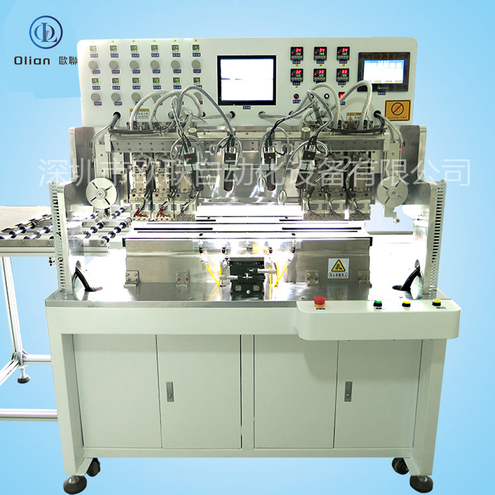
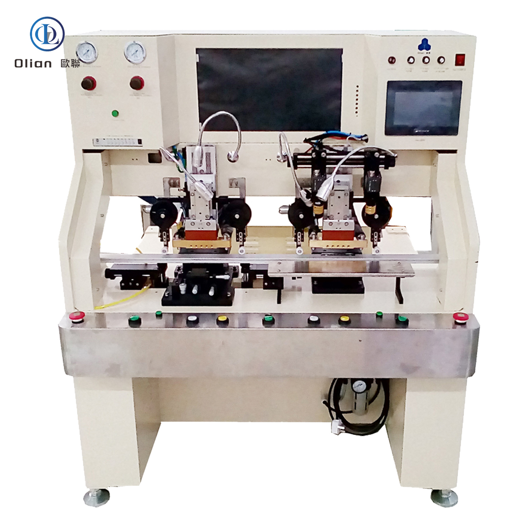
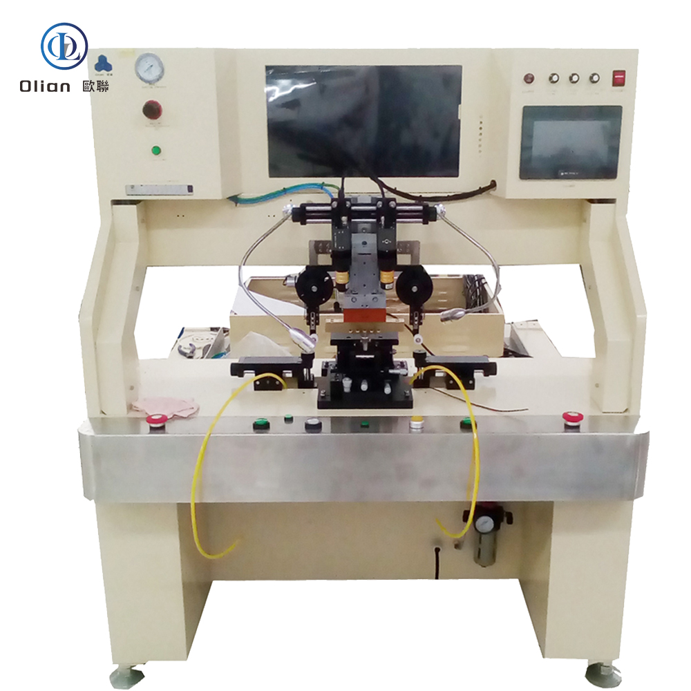
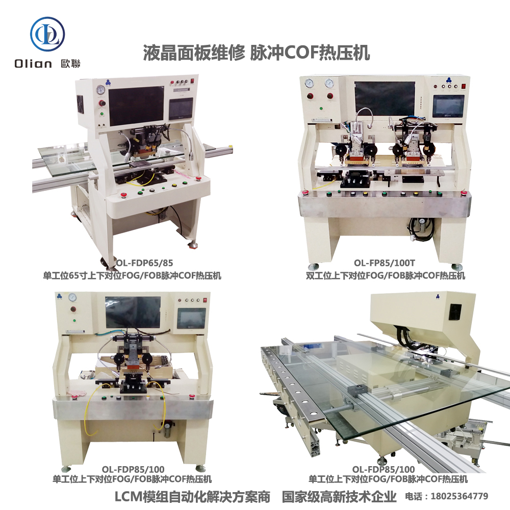
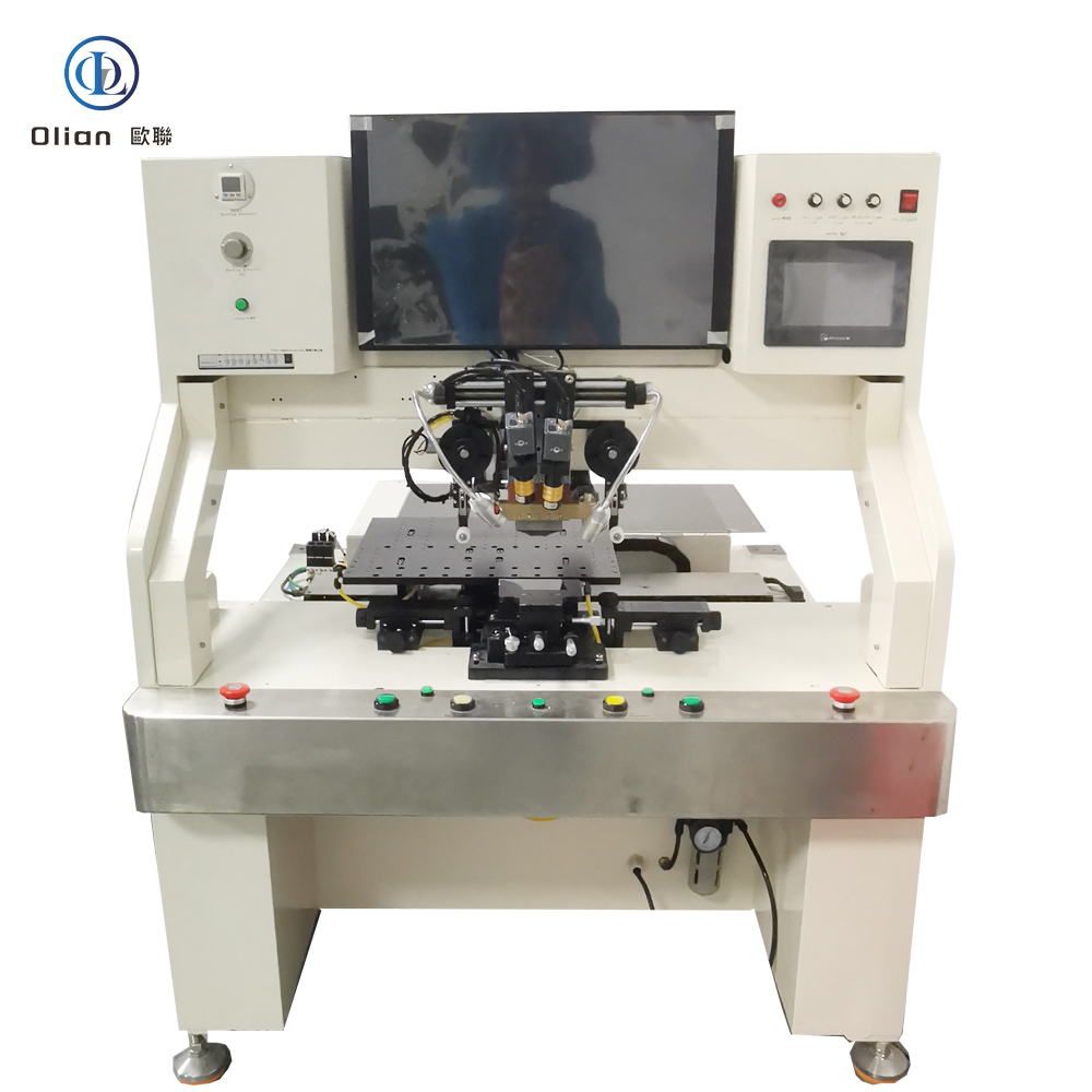
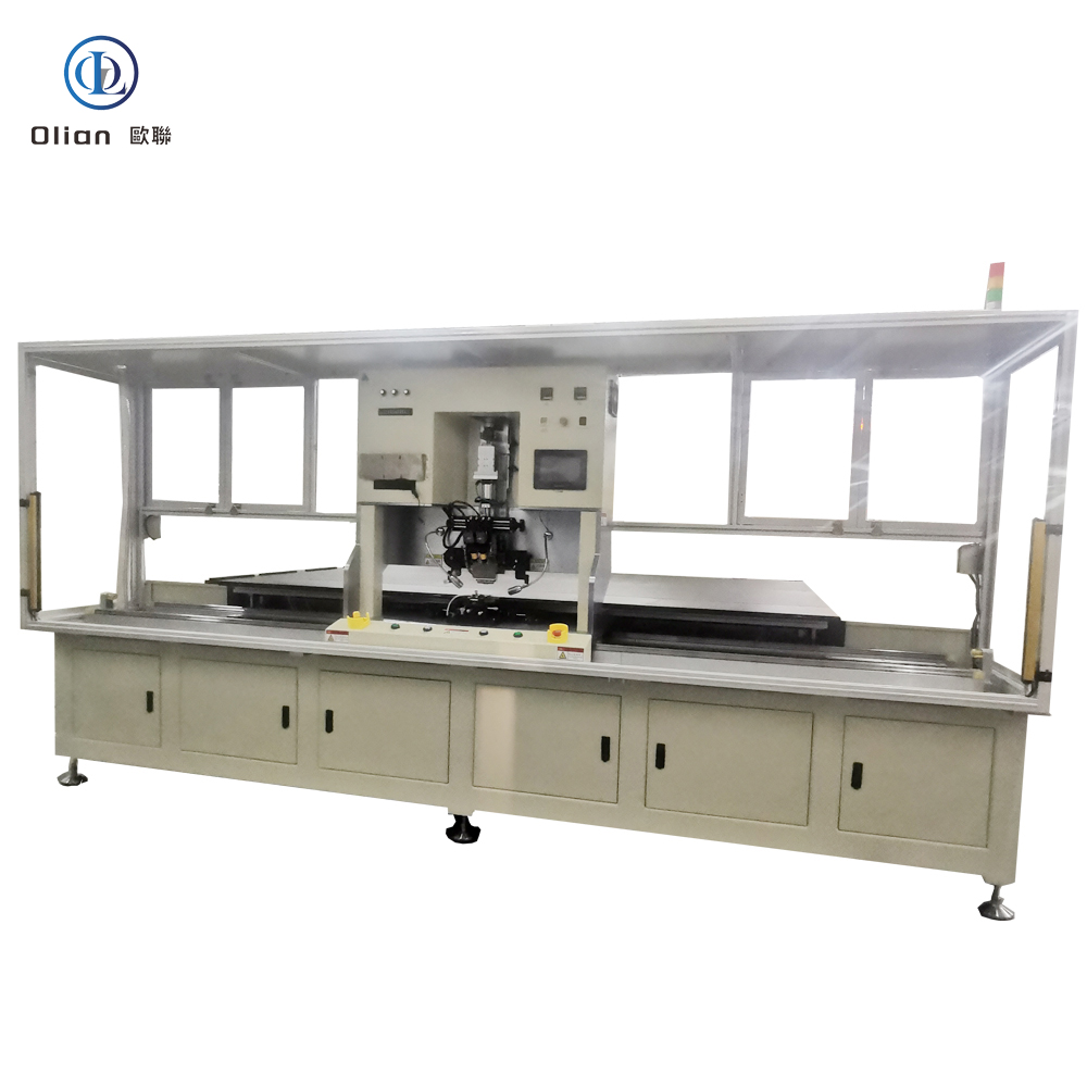
OLB is the acronym for “Outer Lead Bonding”. In a display module the driver IC is first mounted on a flexible polyimide tape (TAB) or on a continuous reel (COF). The inner leads of that tape are bonded to the IC bumps in an earlier process called ILB (Inner Lead Bonding). The outer leads—fine copper traces that fan out beyond the IC—must now be connected to the display glass (for source drivers) or to a rigid PCB (for gate drivers). The machine that executes this final link is called an OLB bonding machine. It uses anisotropic conductive film (ACF) to create thousands of vertical contacts while remaining insulating laterally, then folds the tail 180° so the IC disappears behind the panel, shrinking the bezel to under 1 mm.
COG (Chip-On-Glass) works well for phones, but for 32″-120″ TVs the driver ICs generate too much heat to be parked on the glass. COF (Chip-On-Film) brings the IC onto a flex tail, but the tail must still exit sideways before folding—OLB is the step that actually welds that tail to the glass or PCB. The process is repair-friendly: a defective tail can be removed and rebonded without scrapping the entire panel. Automotive Tier-1 suppliers also rely on OLB because it survives 1,000 h of 85 °C/85 % RH and −40 °C to +105 °C thermal cycling required
Bonding Head: Titanium alloy, diamond-lapped to 0.3 µm flatness, DLC-coated for anti-stick, lasts 300,000 cycles.
Pulse Heater: 800 W cartridge, embedded K-type thermocouple, ramp 200 °C/s, overshoot < 0.5 °C.
Force Actuator: Voice-coil or servo motor, 24-bit encoder, 0.1 N resolution, 2 ms response; active gravity cancellation for 0.4 mm glass.
Vision System: 12 MP global-shutter CMOS, telecentric lens, coaxial + side LED, sub-pixel edge detection repeatable to 0.2 µm.
Motion Stage: Cross-roller bearings, 0.05 µm linear encoder, servo feedback at 20 kHz, granite base with passive vibration isolation.
ACF Feed Unit: Stepper-driven, tungsten-steel cutter, anti-static vacuum, waste take-up spool, splice sensor for uninterrupted production.
Real-time Linux kernel guarantees < 1 ms jitter; PID temperature loop updated at 10 kHz.
Recipe manager encrypts parameters—temperature, pressure, time, ramp rate—per product QR code.
AI vision self-learns new pad patterns from panel vendors, reducing setup time 70 %.
MES interface via OPC-UA uploads cycle data, resistance values, and images for full traceability.
Cloud dashboard predicts heater degradation and schedules maintenance before scrap occurs.
LCD & OLED TV: 32″-120″ 4K/8K panels—bonding source COF tails to glass edge, gate COF tails to PCB.
Automotive: Curved instrument clusters, 15 inch OLED infotainment, head-up displays—passing 1,000 h 85 °C/85 % RH.
Medical: Surgical monitors, portable ultrasound, wearable patches—biocompatible polyimide, ISO 13485 traceability.
Industrial & Military: Avionics displays, factory HMI panels, rugged handhelds—shock, altitude, fungus per MIL-STD-810.
OLB bonding machine, OLB bonder, outer lead bonding equipment, TAB OLB bonding, COF OLB bonding, LCD OLB repair machine, OLED OLB bonding, 8K OLB bonding, 100 inch OLB bonding, automotive OLB bonding, medical OLB bonding, pulse heat OLB bonding, constant temperature OLB bonding, ACF OLB bonding, AI vision OLB bonding, IoT OLB bonding machine, China OLB bonding machine, automatic OLB bonder, OLB bonding accuracy 1 micron, OLB bonding temperature 220 C, OLB bonding pressure 1 MPa, vertical conduction horizontal insulation, lead-free OLB bonding, ROHS compliant OLB bonding.
Copper-Core ACF: Cu-Ag particles cut material cost 50 % while keeping < 20 mΩ contact resistance.
Green Refrigerants: Closed-loop cooling replaces water with R1234ze, reducing carbon footprint 30 %.
AI-Driven Profiles: Neural networks auto-optimize temperature ramps for each polyimide type, pushing yield to 99.9 %.
Cold-Laser Fold Assist: Femtosecond laser pre-scores the coverlay, enabling 90° fold with 50 µm radius and zero trace damage.
Servo-Hydraulic Hybrid: Delivers 80 kg force for 100″ TV OLB tails while keeping 1 µm position accuracy.
Dual-Head Systems: Parallel bonding of source and gate OLBs doubles throughput without extra floor space.
An OLB bonding machine is no longer a niche display tool—it is the critical gateway between microscopic IC bumps and macroscopic screen signals. By mastering sub-micron alignment, single-degree thermal control and real-time force feedback, the latest OLB bonders deliver sub-3-second cycles with 99.9 % yield and full Industry 4.0 traceability. Whether you are a display OEM chasing 0.9 mm bezels, an automotive Tier-1 qualifying 100-inch curved clusters, or a repair center reworking $300 TV panels, investing in an AI-enhanced, IoT-connected OLB bonding platform future-proofs your process.
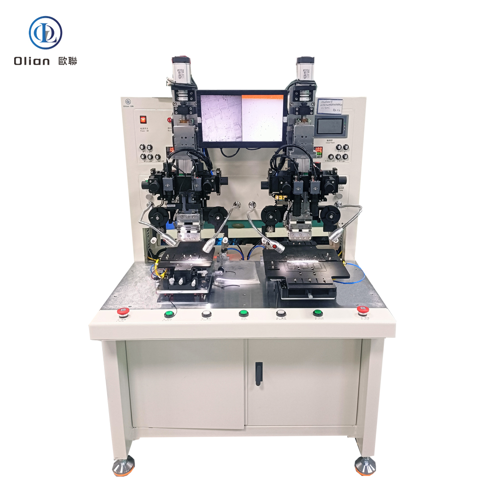
A FOB bonding machine—short for Flex-On-Board or Film-On-Board—is the critical link between a floppy polyimide tail and a rigid printed-circuit board. It grabs a flexible printed circuit (FPC), aligns it to a PCB within a single micron, and welds the copper traces together with anisotropic conductive film (ACF) in under three seconds. The result is a vibration-proof, heat-proof, lead-free joint that survives −40 °C automotive winters and +105 °C engine-bay summers. This guide walks through physics, hardware, software, specs, applications, trends, and maintenance rank you for “FOB bonding machine”, “FOB bonder”, “FPC to PCB bonding”, “ACF FOB machine”, “automotive FOB bonding”,
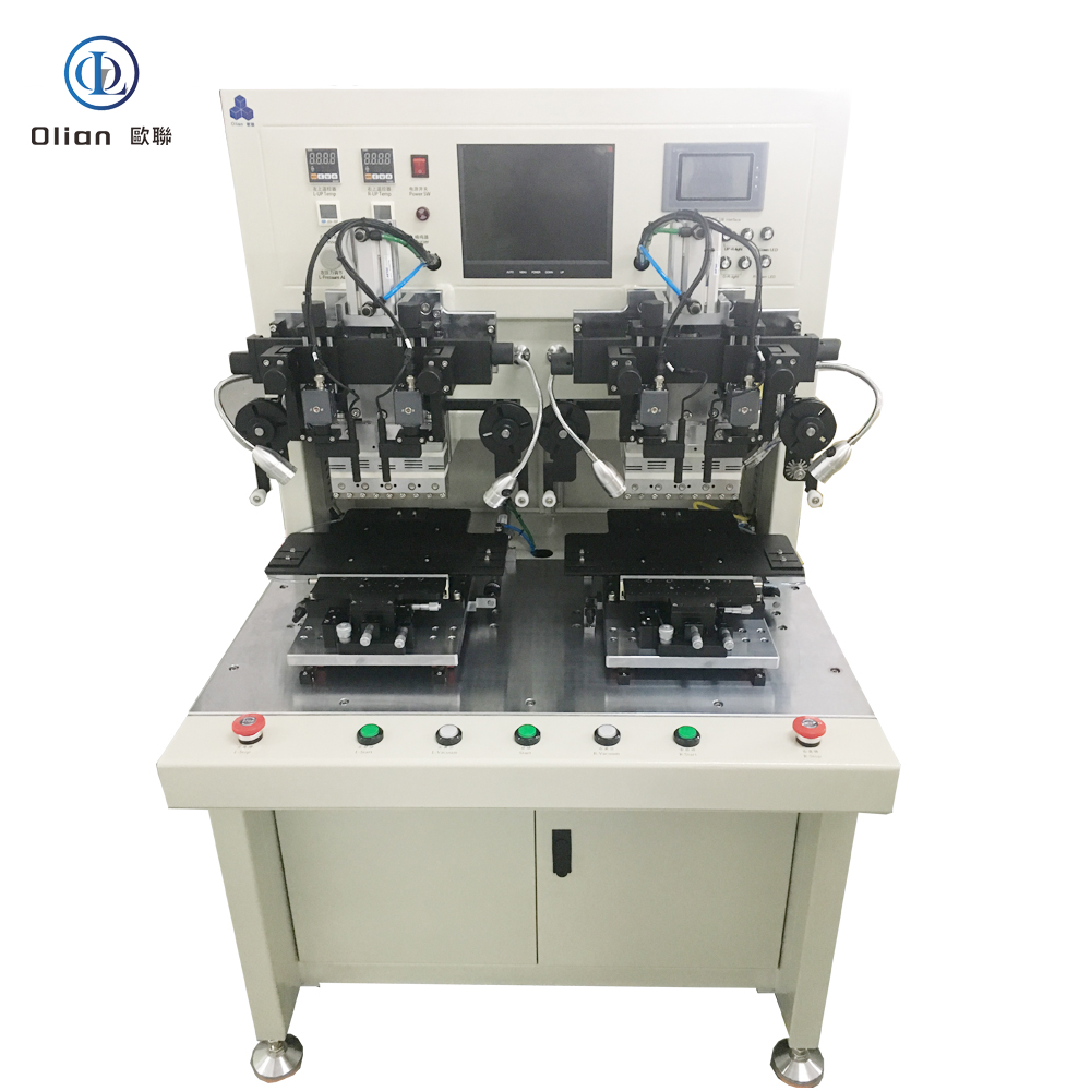
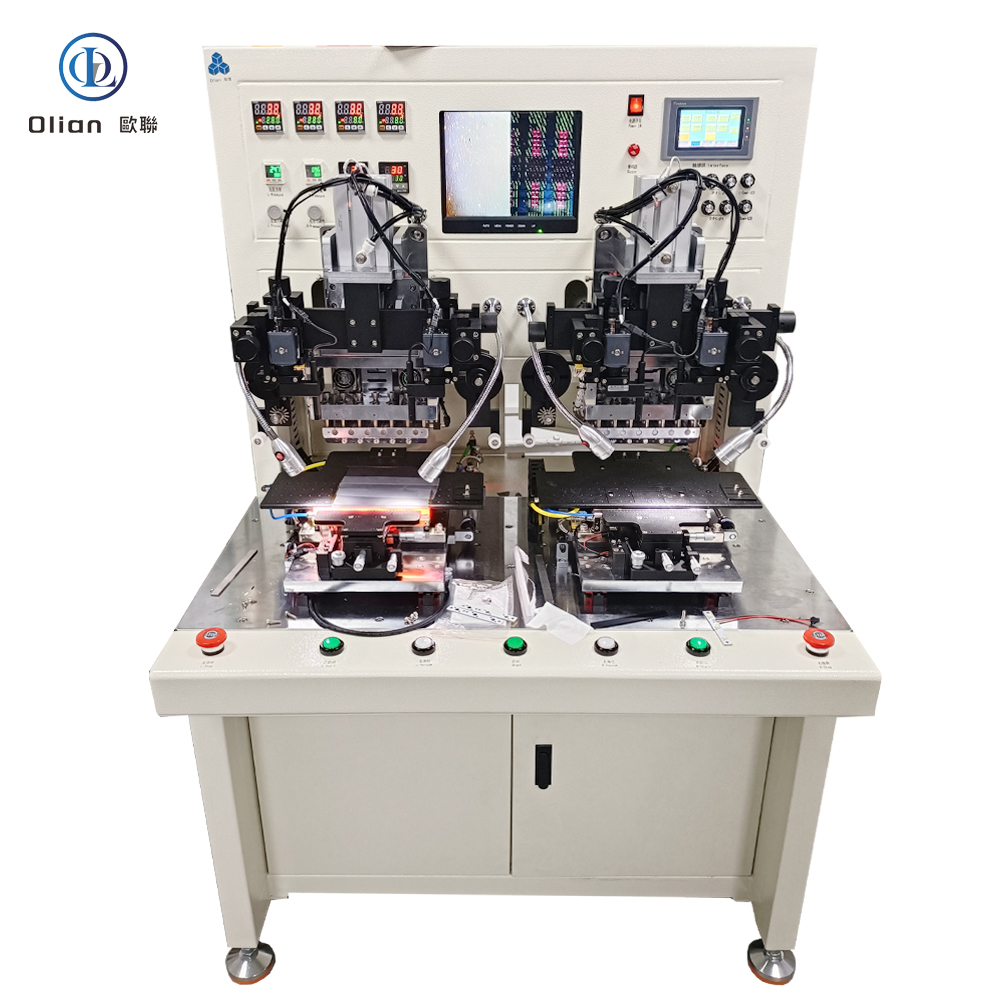
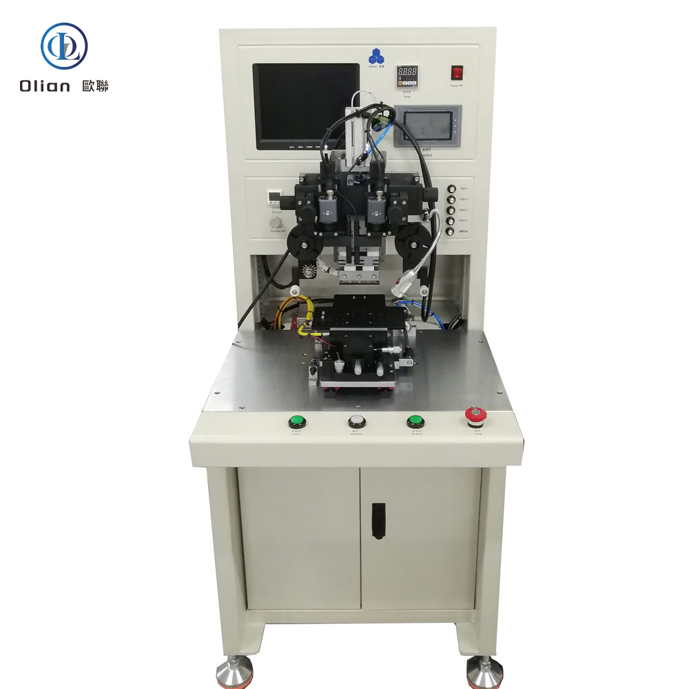
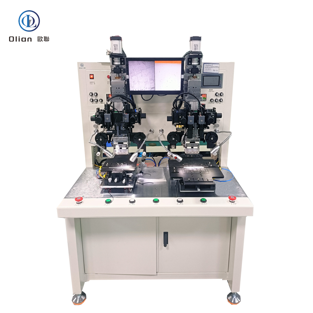
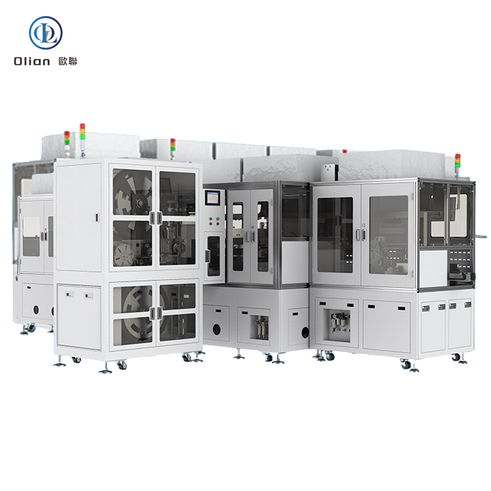
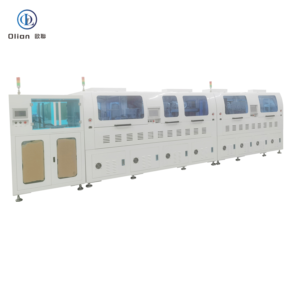
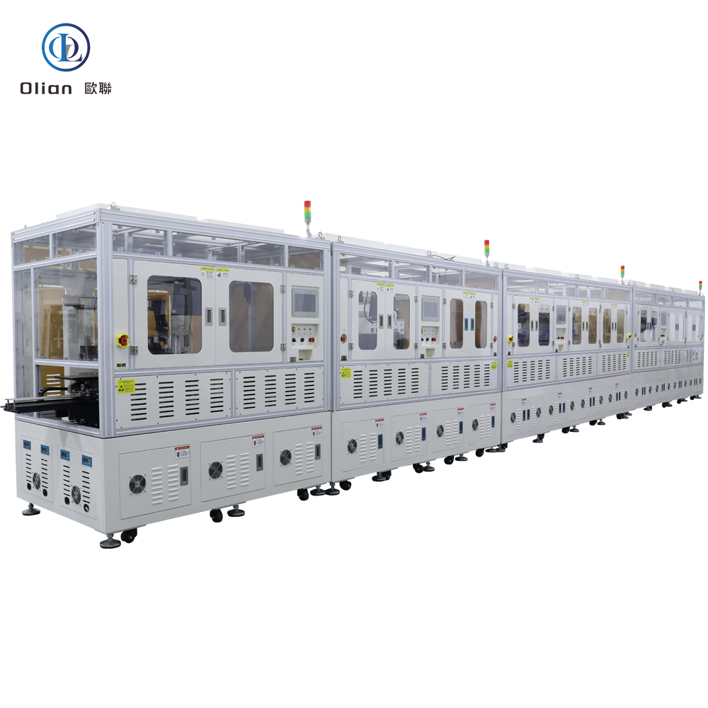
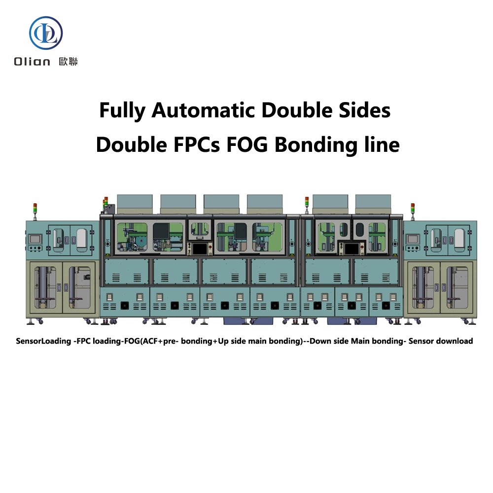
A FOB bonding machine is a servo-driven, vision-guided, pulse-heat press that laminates anisotropic conductive film onto a PCB, then bonds a flexible printed circuit (FPC) or chip-on-film (COF) tail to that PCB with micron-level accuracy. The film contains nickel or gold-coated spheres that conduct only vertically, giving thousands of simultaneous contacts while remaining insulated laterally. The same platform reworks defective boards by removing the old ACF and rebonding a new tail, saving a $200 automotive cluster or a $150 tablet mainboard.
Rigid PCBs cannot fold; wire harnesses fail after 10,000 vibration cycles; connectors add height and cost. FOB eliminates all three pain points by folding a 25 µm polyimide tail 180° with 0.2 mm radius and locking it to the PCB in a 2-second cycle. Automotive Tier-1 suppliers prefer FOB because it passes AEC-Q100 Grade 0 (−40 °C to +150 °C) without a single connector contact. Consumer OEMs love the 0.9 mm board-edge profile that enables edge-to-edge displays.
Bonding Head: Titanium alloy, diamond-lapped to 0.3 µm flatness, DLC-coated for anti-stick, lasts 300,000 cycles.
Pulse Heater: 800 W cartridge, embedded K-type thermocouple, ramp 200 °C/s, overshoot < 0.5 °C.
Force Actuator: Voice-coil or servo motor, 24-bit encoder, 0.1 N resolution, 2 ms response; active gravity cancellation for 25 µm PCBs.
Vision System: 12 MP global-shutter CMOS, telecentric lens, coaxial + side LED, sub-pixel edge detection repeatable to 0.2 µm.
Motion Stage: Cross-roller bearings, 0.05 µm linear encoder, servo feedback at 20 kHz, granite base with passive vibration isolation.
ACF Feed Unit: Stepper-driven, tungsten-steel cutter, anti-static vacuum, waste take-up spool, splice sensor for uninterrupted production.
Real-time Linux kernel guarantees < 1 ms jitter; PID temperature loop updated at 10 kHz.
Recipe manager encrypts parameters—temperature, pressure, time, ramp rate—per product QR code.
AI vision self-learns new pad patterns from PCB suppliers, reducing setup time 70 %.
MES interface via OPC-UA uploads cycle data, resistance values, and images for full traceability.
Cloud dashboard predicts heater degradation and schedules maintenance before scrap occurs.
Consumer Electronics: Smartphone mainboard, tablet battery flex, laptop keyboard backlight, smartwatch heart-rate sensor.
TV & Signage: 32″–100″ 4K/8K LCD, OLED, mini-LED—bonding source COF tails to main PCB.
Automotive: Curved instrument clusters, 15 inch OLED infotainment, head-up displays, camera modules—passing 1,000 h 85 °C/85 % RH.
Medical: Surgical hand-piece flex, portable ultrasound mainboard, wearable ECG patch—biocompatible polyimide, ISO 13485 traceability.
Industrial & Military: Avionics displays, factory HMI panels, rugged handhelds—shock, altitude, fungus per MIL-STD-810.
FOB bonding machine, FOB bonder, FPC to PCB bonding, ACF FOB machine, flex-on-board bonding, Film-on-board bonder, pulse heat FOB bonding, constant temperature FOB bonding, automotive FOB bonding, medical FOB bonding, 0.2 mm fold radius FOB, 25 µm polyimide FOB bonding, 100 inch FOB bonding, AI vision FOB bonding, IoT FOB bonding machine, China FOB bonding machine, automatic FOB bonder, FOB bonding accuracy 1 micron, FOB bonding temperature 200 C, FOB bonding pressure 1 MPa, vertical conduction horizontal insulation, lead-free FOB bonding, ROHS compliant FOB bonding.
Copper-Core ACF: Cu-Ag particles cut material cost 50 % while keeping < 20 mΩ contact resistance.
Green Refrigerants: Closed-loop cooling replaces water with R1234ze, reducing carbon footprint 30 %.
AI-Driven Profiles: Neural networks auto-optimize temperature ramps for each polyimide type, pushing yield to 99.9 %.
Micro-LED Bridge: Same FOB platform bonds 20 µm × 20 µm micro-LED dies onto flexible PCBs.
Cold-Laser Fold Assist: Femtosecond laser pre-scores the coverlay, enabling 90° fold with 50 µm radius and zero trace damage.
Servo-Hydraulic Hybrid: Delivers 80 kg force for 100″ TV FOB tails while keeping 1 µm position accuracy.
A FOB bonding machine is no longer a niche flex-to-board press—it is the critical enabler for foldable smartphones, zero-bezel TVs, curved automotive clusters, and biocompatible medical wearables that define 2025 consumer expectations. By mastering sub-micron alignment on 25 µm polyimide, pulse-heat control within half a degree, and real-time force feedback, the latest FOB bonders deliver sub-3-second cycles with 99.9 % yield and full Industry 4.0 traceability. Whether you are a display OEM chasing a 0.9 mm chin, an automotive Tier-1 qualifying radar modules, or a medical start-up prototyping flexible patches, investing in an AI-enhanced, IoT-connected FOB bonding platform future-proofs your process.
An IC bonding machine is the beating heart of every microelectronic package you touch—whether it’s the OLED display in your foldable phone, the radar sensor in your car, or the memory stack in your laptop. It is the precision system that places a bare silicon die onto a substrate—glass, flex, PCB, or lead-frame—and then creates permanent electrical joints by thermo-compression, ultrasonic, or eutectic means. Keywords”IC bonding machine”, “IC die bonder”, “wire bonding machine”, “eutectic IC bonder”, “flip-chip bonder”, “COG bonding machine”, “COB bonding machine”, “thermosonic bonding”, “ultrasonic wire bonder.
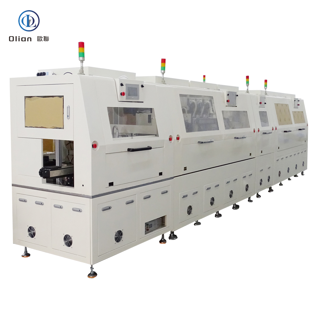
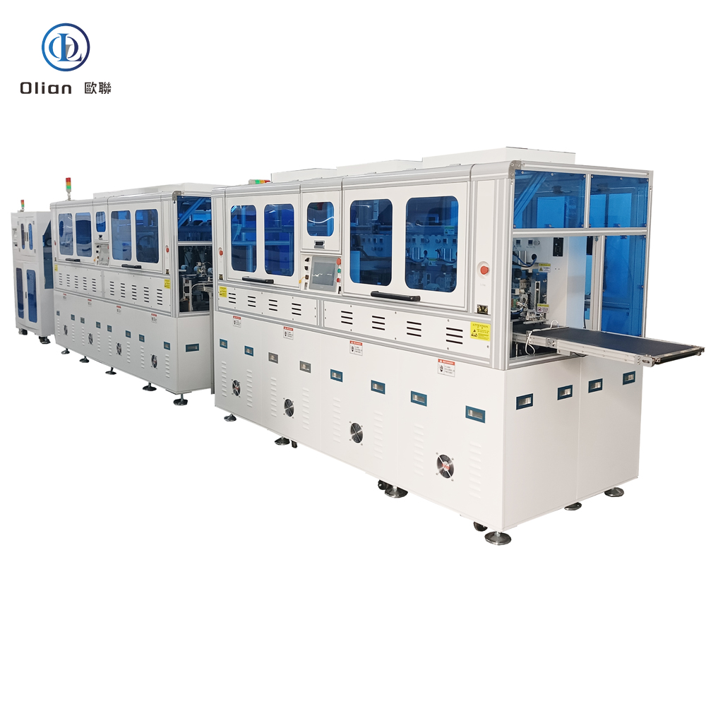
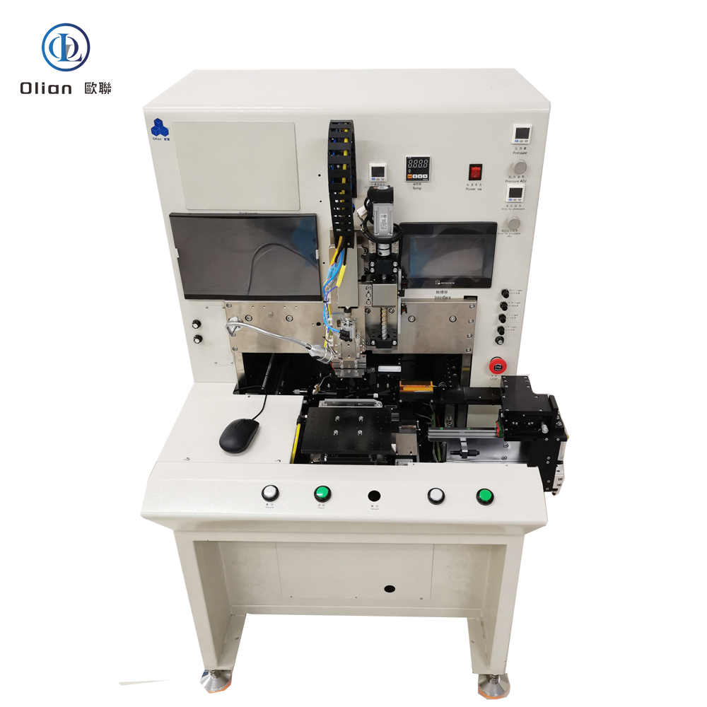
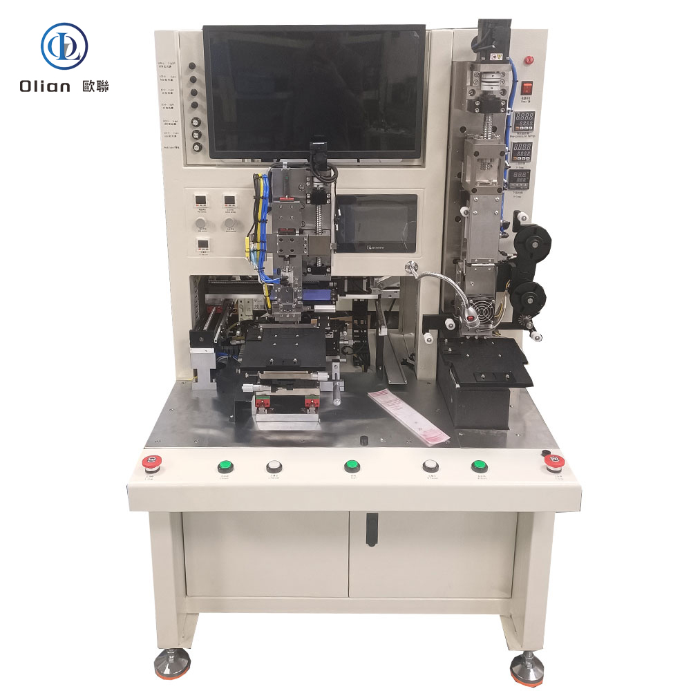
An IC bonding machine is a high-precision mechatronic platform that picks up a bare integrated-circuit die from a wafer, waffle pack, or gel-pak, places it with micron accuracy onto a target substrate, and then forms electrical and mechanical joints by one of three core methods: wire bonding (thermosonic or ultrasonic), flip-chip thermo-compression, or eutectic/solder reflow. Modern platforms achieve ±1 µm placement accuracy, ±0.3 ° angular repeatability, and 0.1 g force resolution on die sizes from 0.25 mm × 0.25 mm to 25 mm × 25 mm. The same machine also reworks defective packages by removing the old die and rebonding a new one.
Gold or copper bumps on the die must touch copper pads on the substrate. At room temperature the native oxide layer prevents reliable contact. Thermosonic wire bonding uses 150 °C stage heat plus 60 kHz ultrasonic energy to break the oxide and form Au-Al intermetallics. Flip-chip thermo-compression applies 200 °C and 1 MPa to deform gold or solder bumps, creating cold-weld joints. Eutectic bonding raises temperature above 280 °C so Au-Sn or Cu-Sn forms a liquid phase that solidifies into a void-free joint. Each method demands closed-loop temperature, force, and time control to within 1 %.
Die Bond Head: Ceramic or titanium collet, 0.1 µm run-out, vacuum channel optimized for 50 µm thin die.
Ejector Stage: Triple-needle system with 1 µm z-repeatability, adjustable stroke 0–3 mm, anti-crumple software.
Linear Motors: Iron-less design, 5 g acceleration, 0.05 µm encoder resolution, backlash-free for < 1 ms settling.
Force Sensor: Strain-gauge or optical, 0.1 g resolution, 10 kHz bandwidth, real-time overload protection.
Temperature Stack: Pulse-heated stage 25–500 °C, ramp 100 °C/s, uniformity ±1 °C across 300 mm wafer.
Vision Trains: Dual 12 MP cameras, telecentric lenses, coaxial + side LED, AI edge detection repeatable to 0.2 µm.
Wire Feed System: Ultrasonic cleaner, flame-off electrode, vacuum tail collector, gold or copper wire 18–75 µm diameter.
Real-time Linux or RTX kernel guarantees < 500 µs jitter; PID loops updated at 20 kHz.
Recipe manager encrypts parameters—temperature profile, force ramp, ultrasonic power—per product QR code.
MES interface via OPC-UA uploads die ID, XY coordinates, bond force, and wire-pull data for full traceability.
AI predictor analyses capillary wear and forecasts ball-shape drift 200 bonds ahead, cutting unplanned downtime 30 %.
Remote VPN allows OEM engineers to debug without on-site visit, saving travel cost and CO₂ footprint.
Consumer Electronics: Smartphone OLED driver, tablet touch MCU, laptop power management IC, memory stack in SSD.
TV & Display: COG bonding of source drivers on 8K LCD/mini-LED panels; COF bonding on curved OLED TVs.
Automotive: Radar MMIC, camera ISP, LED headlamp driver, infotainment processor—qualified to AEC-Q100 Grade 0 (−40 °C to +150 °C).
Medical: MEMS pressure sensors, hearing-aid DSP, catheter imaging chip—biocompatible epoxy, ISO 13485 traceability.
Industrial & Aerospace: FPGA on ceramic substrate, power GaN dies, RF amplifiers in 5G base stations, satellites, and defense systems.
IC bonding machine, IC die bonder, wire bonding machine, thermosonic wire bonder, ultrasonic wire bonder, eutectic IC bonding machine, flip-chip bonder, COG bonding machine, COB bonding machine, TAB bonding machine, ACF IC bonding, pulse-heat IC bonding, 1 micron placement accuracy, 12 inch wafer bonding, memory stack bonding, GaN die bonding, automotive IC bonding, medical MEMS bonding, 5G RF bonding, China IC bonding machine, automatic IC bonder, IC bonding temperature 200 C, IC bonding force 1 MPa, gold wire bonding, copper wire bonding, aluminum wire bonding.
Hybrid Bonders: Single platform switches between wire, flip-chip, and eutectic modes in < 5 min, cutting cap-ex by 40 %.
AI-Driven Calibration: Neural networks auto-learn capillary wear and adjust ultrasonic power, pushing yield to 99.99 %.
Copper Wire Migration: 100 % Cu wire replaces gold, cutting material cost 90 % while maintaining < 30 mΩ resistance.
Cold-Laser Clean: Femtosecond laser removes organic contamination at room temperature, enabling 120 °C low-temp bonds for flexible OLED.
Green Factory: Closed-loop chillers and regenerative brakes on linear motors cut energy per bond 25 %.
Heterogeneous Integration: Same bonder stacks logic, memory, and RF chiplets using hybrid bonding (oxide fusion) with < 100 nm alignment.
An IC bonding machine is no longer a single-purpose press—it is the atomic-level gateway between nanometer transistors and millimeter-scale packages. By mastering sub-micron placement, millisecond thermal control, and real-time force feedback, the latest IC bonders deliver 6-wire-per-second speed, 99.99 % yield, and full Industry 4.0 traceability. Whether you are a display OEM stacking 8K drivers, an automotive Tier-1 qualifying radar MMICs, or a medical start-up packaging MEMS sensors, investing in an AI-enhanced, IoT-connected IC bonding platform future-proofs your process.
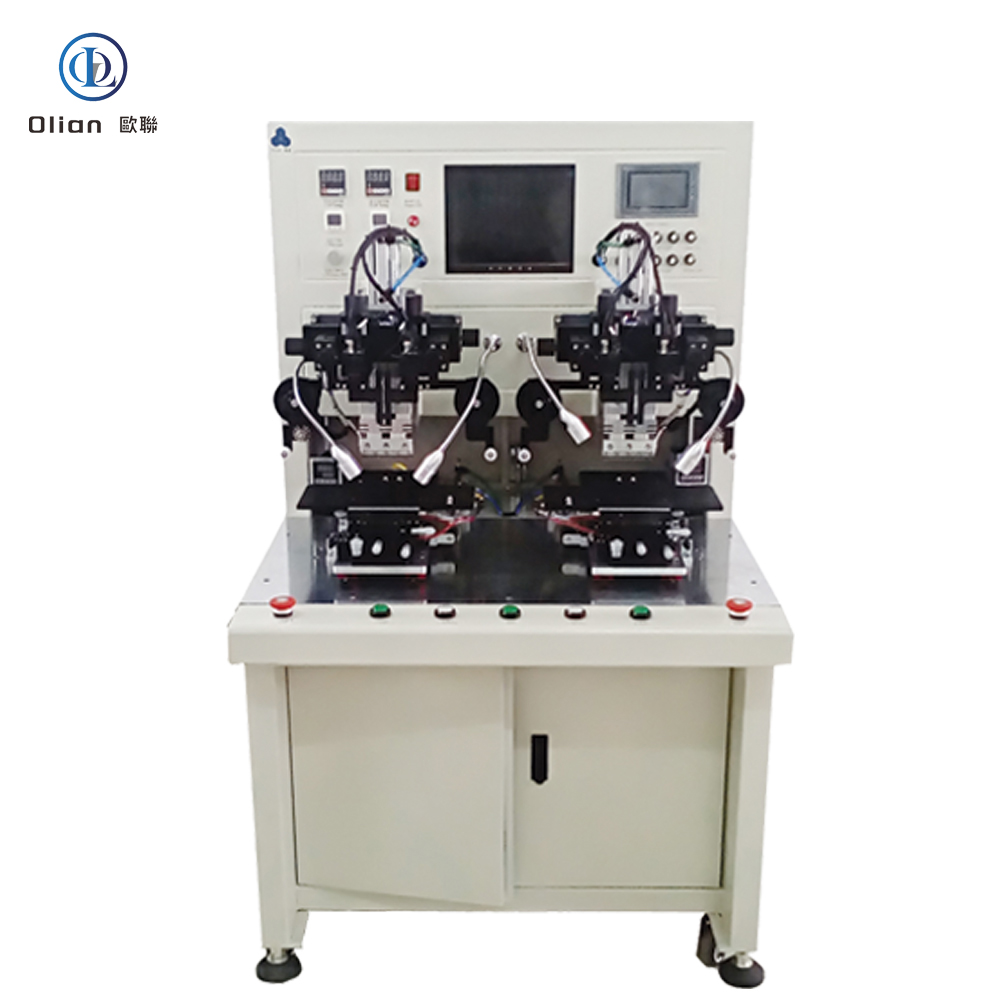
An FPC bonding machine is the silent enabler behind every foldable phone, curved smart-watch, 4K laptop, and automotive cluster you touch today. FPC—Flexible Printed Circuit—must be joined to glass, PCB, or another flex with micron accuracy, vertical conductivity, and horizontal insulation. The equipment that delivers this marriage is a servo-driven, vision-guided, constand temperature and pulse-heat press called an FPC bonding machine. Keywords “FPC bonding machine”, “FPC to glass bonder”, “ACF FPC bonding”, “flex cable bonding equipment”, “pulse heat FPC machine”
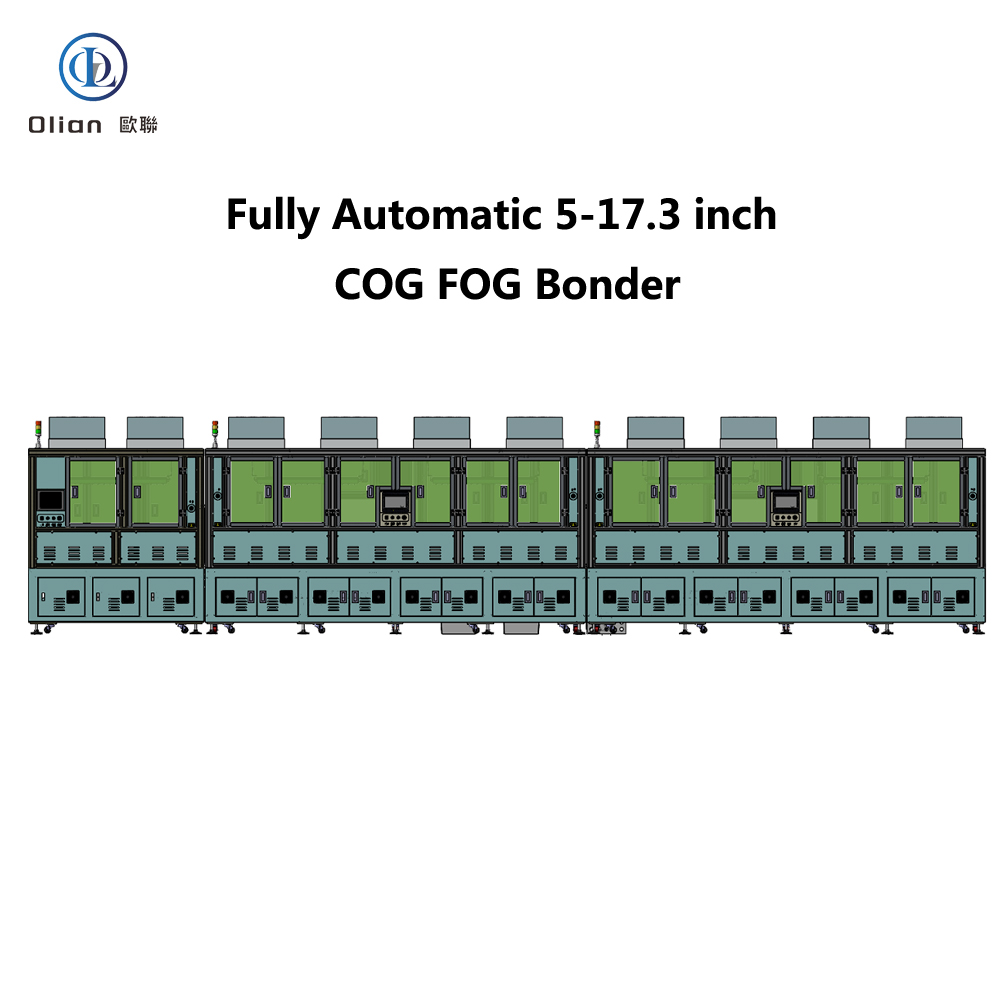

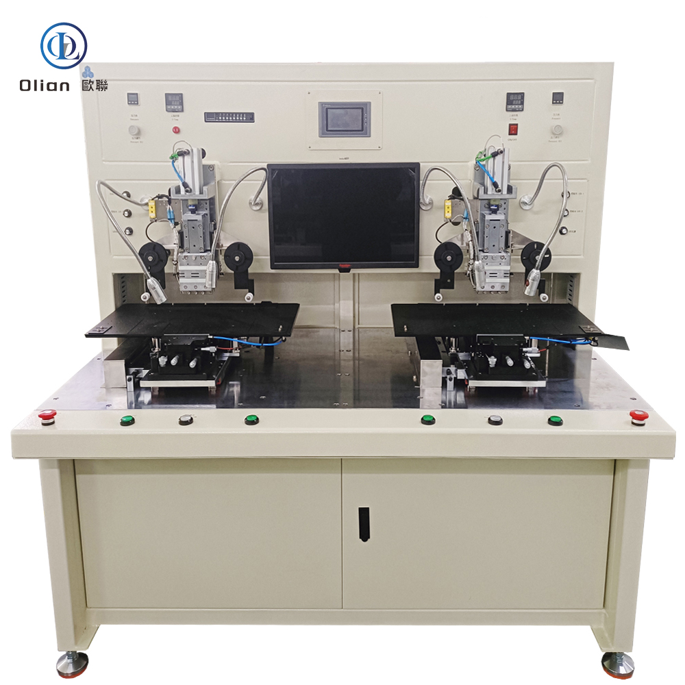
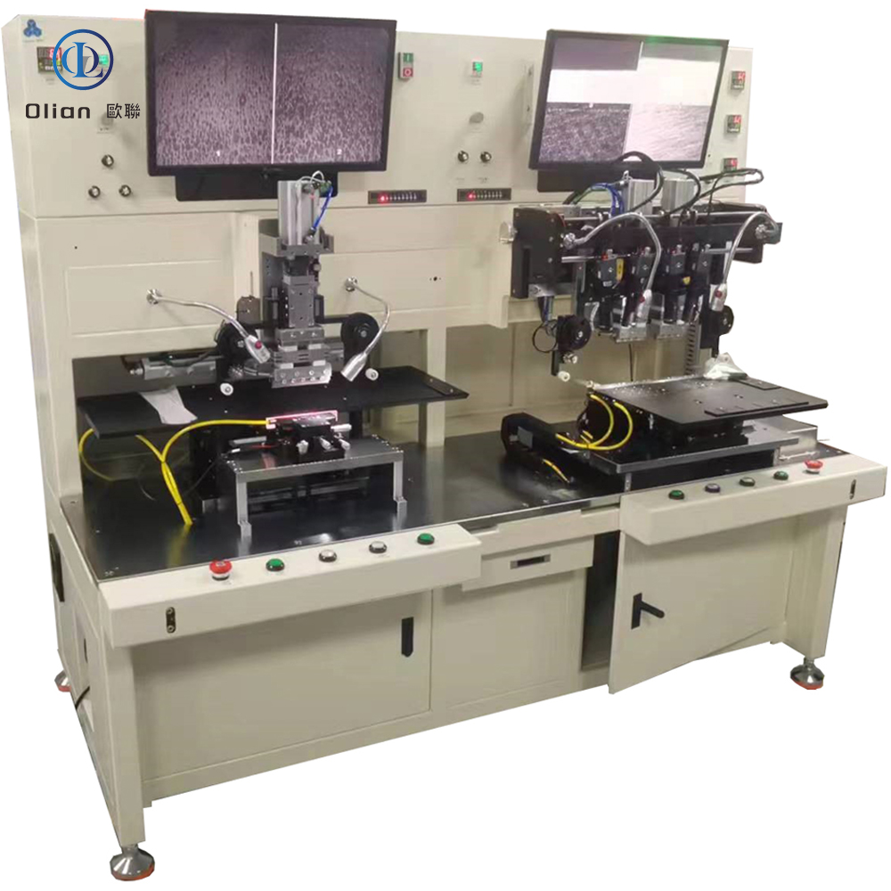
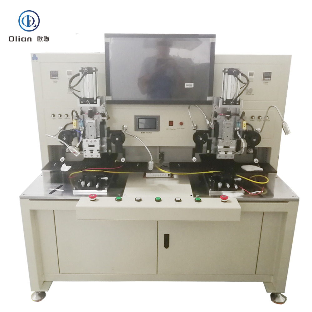
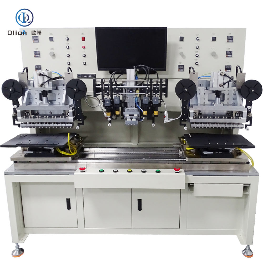
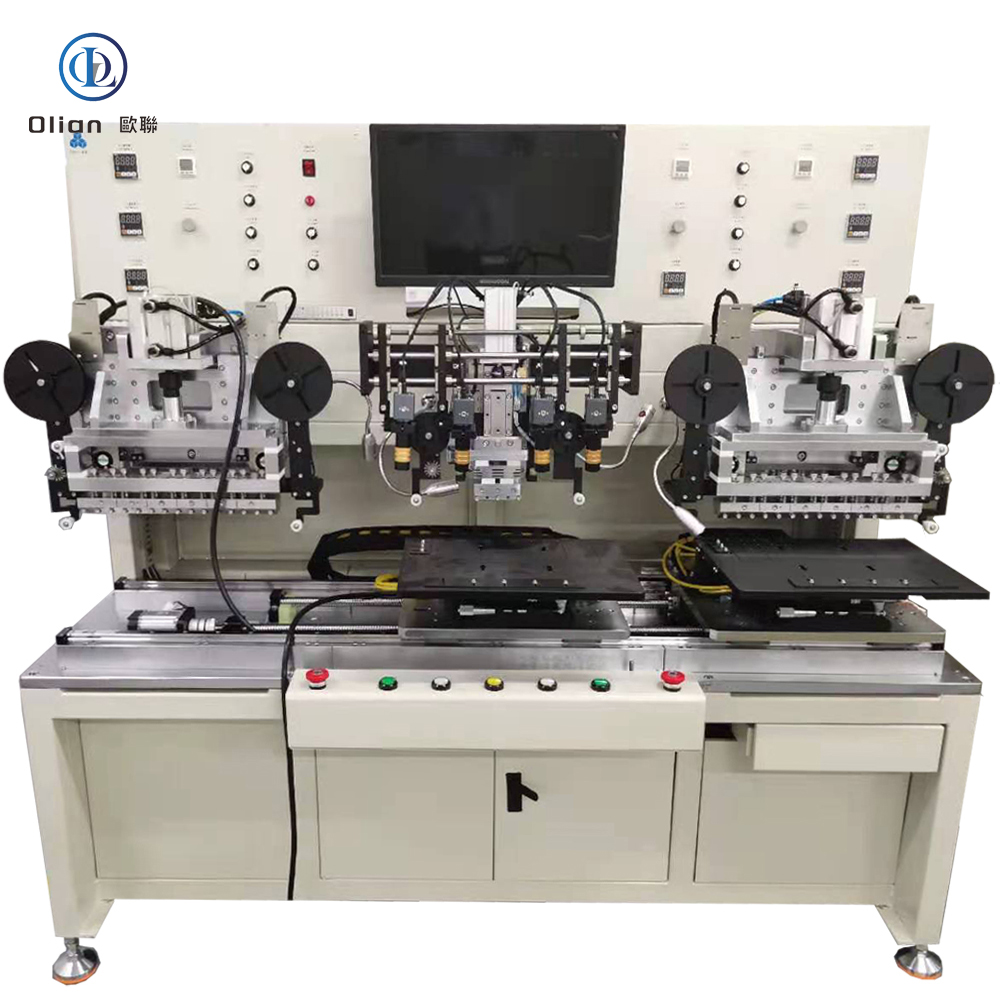
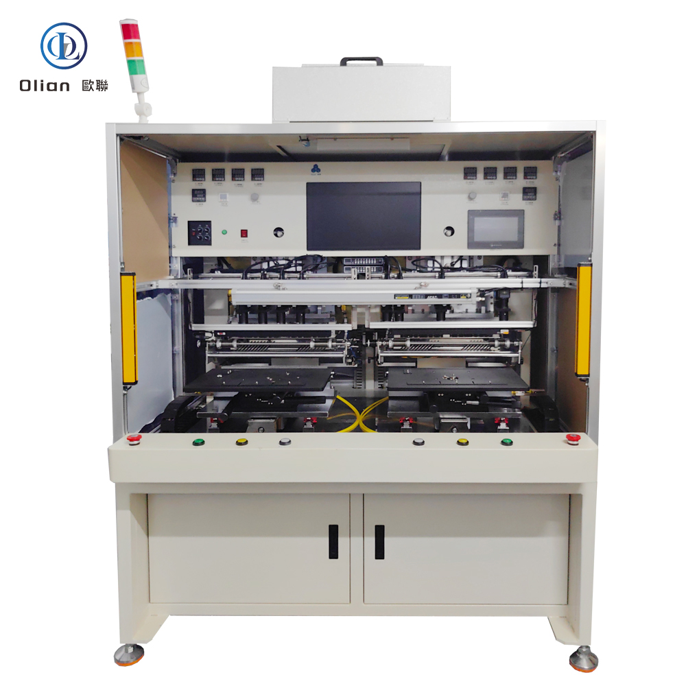
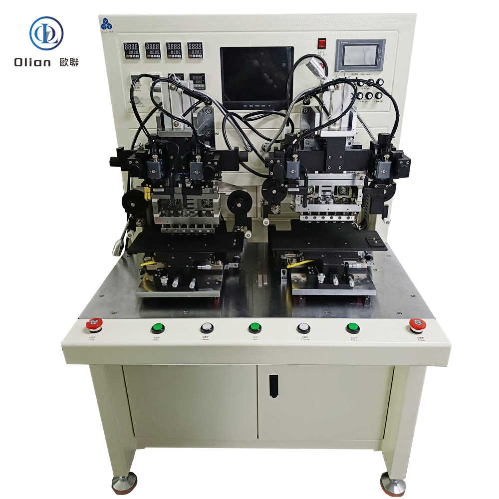
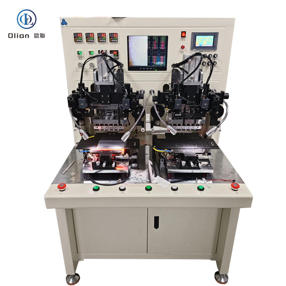
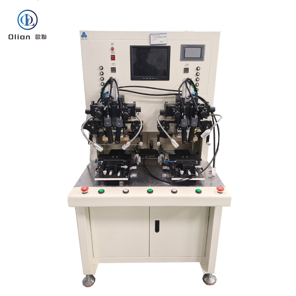

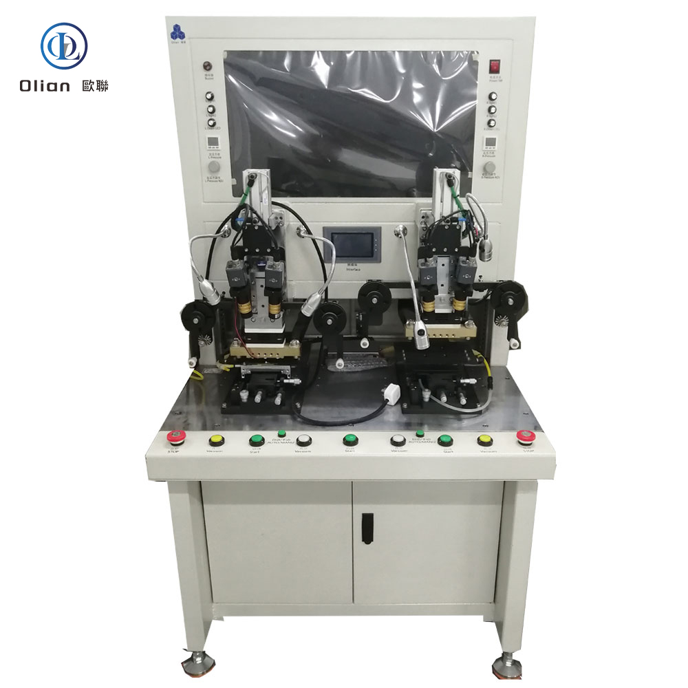
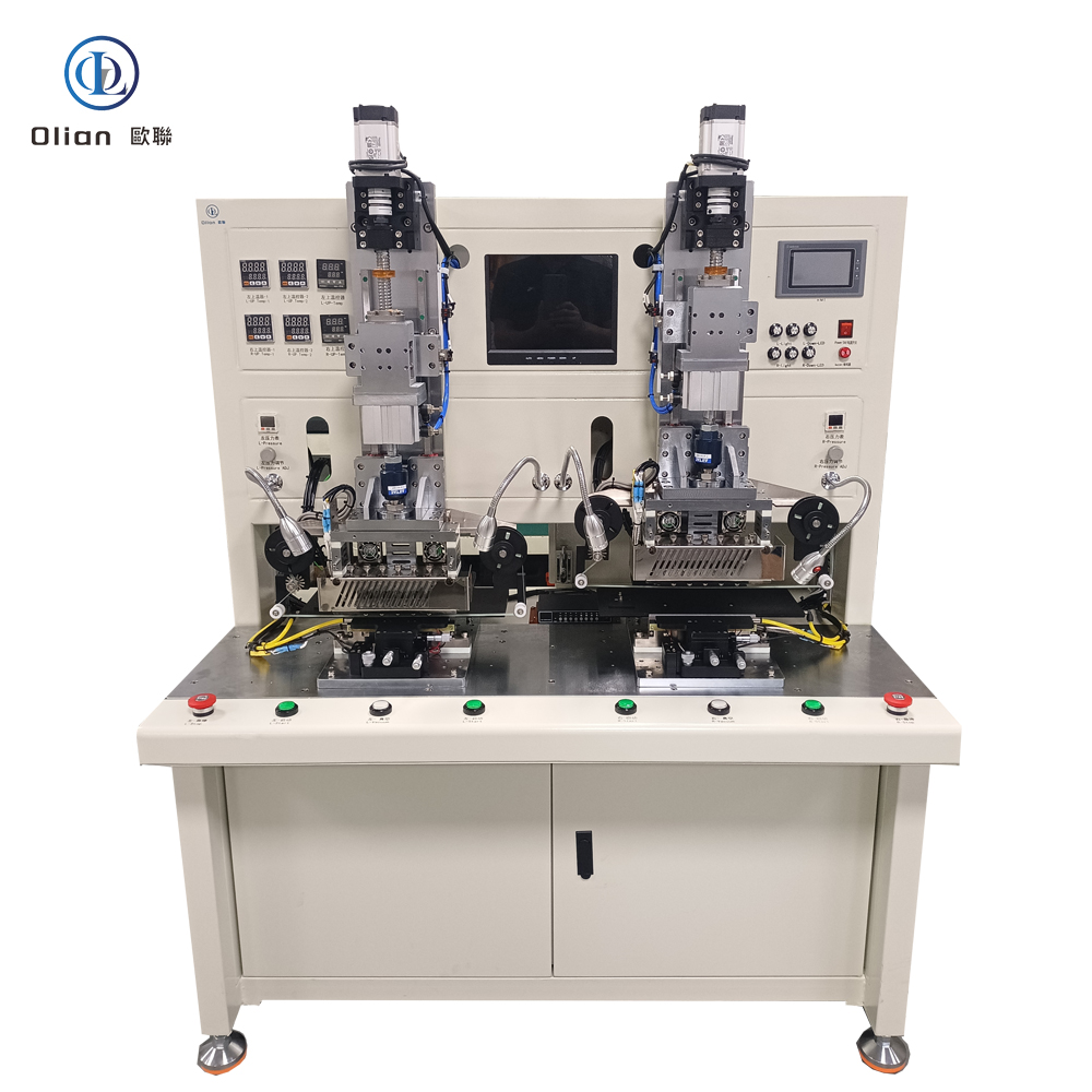
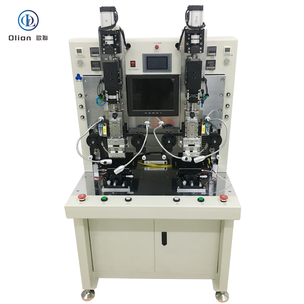
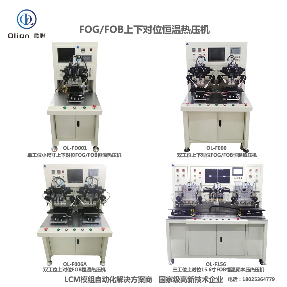
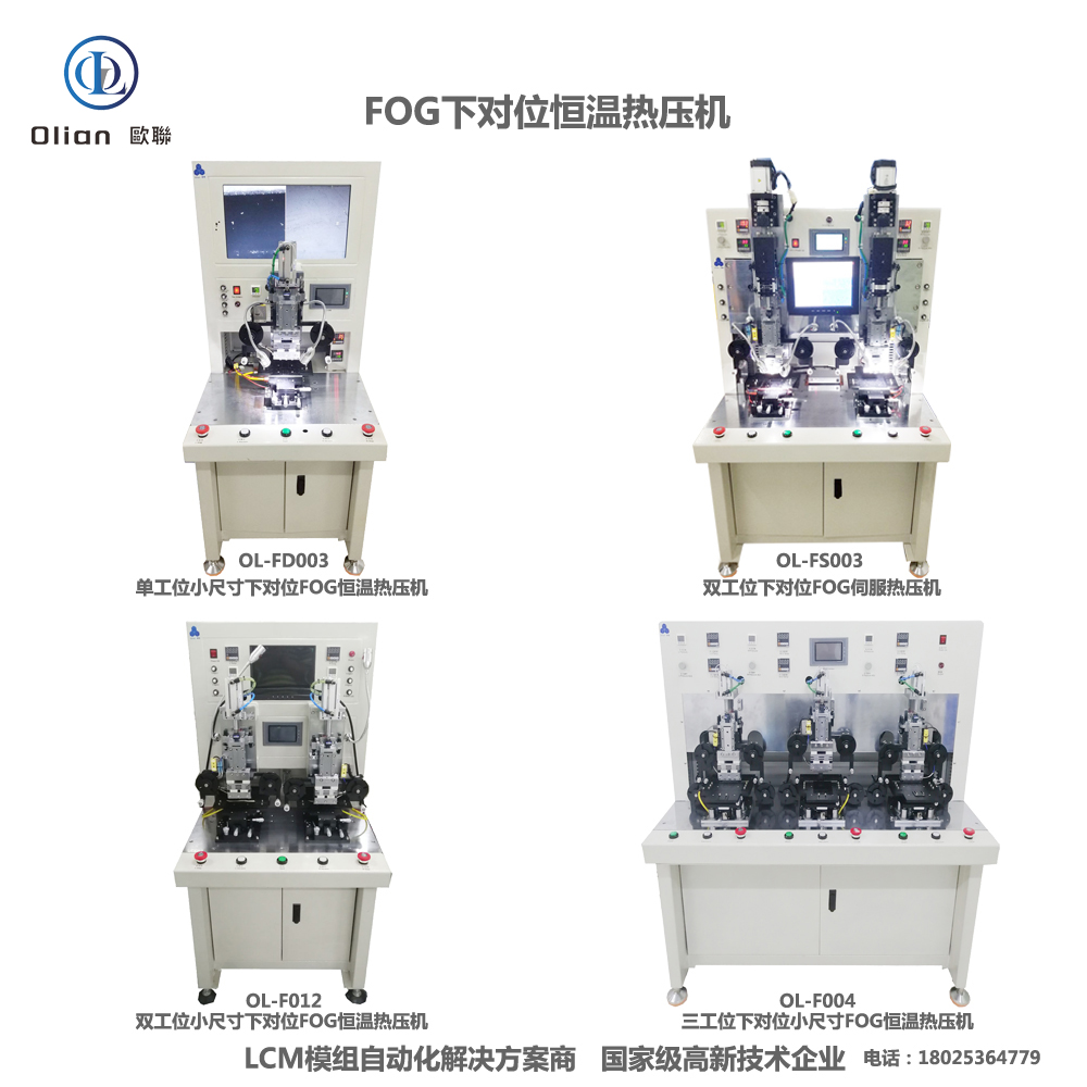
An FPC bonding machine is a high-precision constatn temperature and pulse-heat press that bonds a flexible printed circuit to a rigid or flexible substrate through anisotropic conductive film (ACF) or solder paste. The bond must conduct electricity vertically between copper pads while remaining insulating laterally, must survive 100,000 bend cycles, and must fit inside a 0.9 mm bezel. Modern machines achieve ±1 µm alignment, ±0.5 °C temperature stability, and 0.01 MPa force resolution on substrates as thin as 25 µm and as large as 100-inch TVs.
Foldable phones need a flex tail that folds 180° with 0.2 mm radius—rigid PCB cannot survive. Automotive clusters require vibration resistance from −40 °C to +105 °C—wire harnesses fail. Medical wearables demand biocompatible polyimide—solder joints crack. FPC bonding solves these pain points by combining the flexibility of copper-clad polyimide with the reliability of particle-based conductive adhesive, all while enabling repair: a defective flex can be removed and rebonded without scrapping the entire OLED assembly.
Bonding Head: Titanium alloy, diamond-lapped to 0.3 µm flatness, DLC-coated for anti-stick, lasts 300,000 cycles.
Pulse Heater: 800 W cartridge, embedded K-type thermocouple, ramp 200 °C/s, overshoot < 0.5 °C.
Force Actuator: Voice-coil or servo motor, 24-bit encoder, 0.1 N resolution, 2 ms response; active gravity cancellation for 25 µm substrates.
Vision System: 12 MP global-shutter CMOS, telecentric lens, coaxial + side LED, sub-pixel edge detection repeatable to 0.2 µm.
Motion Stage: Cross-roller bearings, 0.05 µm linear encoder, servo feedback at 20 kHz, granite base with passive vibration isolation.
ACF Feed Unit: Stepper-driven, tungsten-steel cutter, anti-static vacuum, waste take-up spool, splice sensor for uninterrupted production.
Real-time Linux kernel guarantees < 1 ms jitter; PID temperature loop updated at 10 kHz.
Recipe manager encrypts parameters—temperature, pressure, time, ramp rate—per product QR code.
AI vision self-learns new bump patterns from foundries, reducing setup time 70 %.
MES interface via OPC-UA uploads cycle data, resistance values, and images for full traceability.
Cloud dashboard predicts heater degradation and schedules maintenance before scrap occurs.
Consumer Electronics: iPhone, Galaxy Fold, iPad, Apple Watch—bonding display driver, touch MCU, and antenna flex.
TV & Signage: 32″–100″ 4K/8K LCD, OLED, mini-LED—bonding source COF tails to glass.
Automotive: Curved instrument clusters, 15 inch OLED infotainment, head-up displays—surviving −40 °C to +105 °C thermal cycling.
Medical: Surgical monitors, portable ultrasound, wearable patches—biocompatible polyimide, zero flex failure.
Industrial & Military: Avionics displays, factory HMI panels, rugged handhelds—shock, altitude, fungus.
FPC bonding machine, FPC to glass bonder, ACF FPC bonding, flex cable bonding equipment, pulse heat FPC machine, FOG bonding machine, FOB bonding machine, FOF bonding machine, T-FOG bonding machine, foldable phone FPC bonding, 0.9 mm bezel FPC bonding, 25 µm polyimide bonding, 100 inch FPC bonding, automotive FPC bonding, medical FPC bonding, wearable FPC bonding, AI vision FPC bonding, IoT FPC bonding machine, China FPC bonding machine, automatic FPC bonder, FPC bonding accuracy 1 micron, FPC bonding temperature 200 C, FPC bonding pressure 1 MPa, vertical conduction horizontal insulation, lead-free FPC bonding, ROHS compliant FPC bonding.
Copper-Core ACF: Cu-Ag particles cut material cost 50 % while keeping < 20 mΩ contact resistance.
Green Refrigerants: Closed-loop cooling replaces water with R1234ze, reducing carbon footprint 30 %.
AI-Driven Profiles: Neural networks auto-optimize temperature ramps for each polyimide type, pushing yield to 99.9 %.
Micro-LED Bridge: Same FPC platform bonds 20 µm × 20 µm micro-LED dies onto flexible backplanes.
Cold-Laser Fold Assist: Femtosecond laser pre-scores the coverlay, enabling 90° fold with 50 µm radius and zero trace damage.
Servo-Hydraulic Hybrid: Delivers 80 kg force for 100″ TV flex tails while keeping 1 µm position accuracy.
An FPC bonding machine is no longer a niche flex-circuit tool—it is the critical enabler for foldable OLED, zero-bezel wearables, and curved automotive clusters that define 2025 consumer expectations.
By mastering sub-micron alignment on 25 µm polyimide, pulse-heat control within half a degree, and real-time force feedback, the latest FPC bonders deliver sub-3-second cycles with 99.9 % yield and full Industry 4.0 traceability.
Whether you are a display OEM chasing a 0.9 mm chin, a foldable-phone refurbisher reworking OLED modules, or a micro-LED start-up prototyping smart-glass, investing in an AI-enhanced, IoT-connected FPC bonding platform future-proofs your process.
ACF Bonding Machine
An ACF bonding machine is the precision heart of every modern display factory and repair lab.
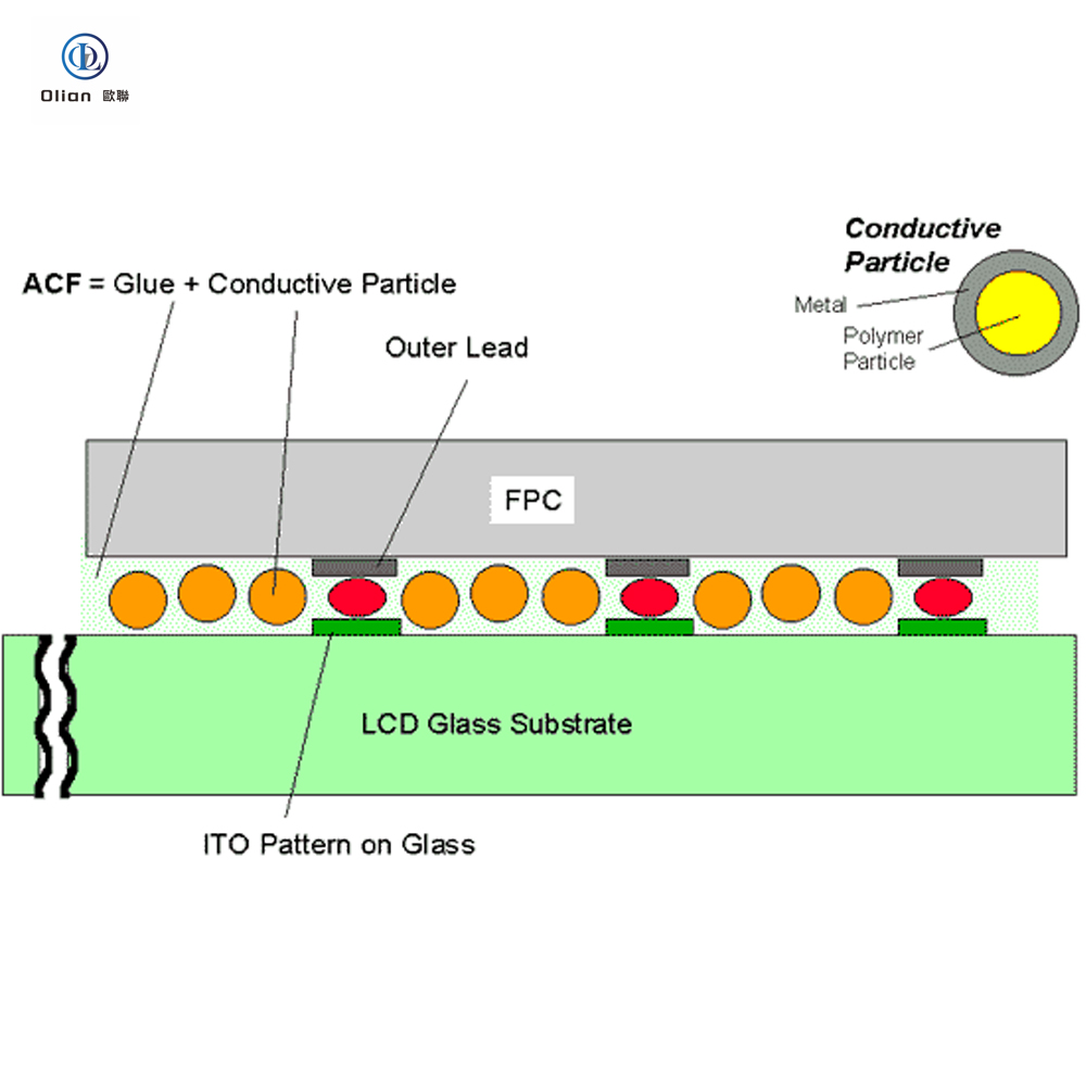
ACF—Anisotropic Conductive Film—contains microscopic nickel or gold-coated spheres suspended in an adhesive resin.
When heat and pressure are applied, those particles touch only in the Z-axis, giving vertical conductivity while remaining insulating horizontally.
The machine that choreographs this three-second micro-explosion must control temperature within half a degree, pressure within a tenth of a bar, and alignment within a single micron.
High-value keywords.:”ACF bonding machine”, “ACF bonder”, “LCD ACF bonding”, “pulse-heat ACF machine”, “TV panel ACF repair”
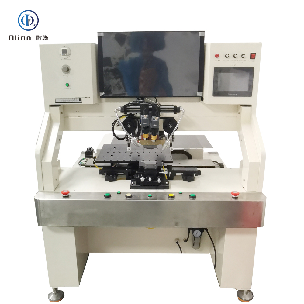
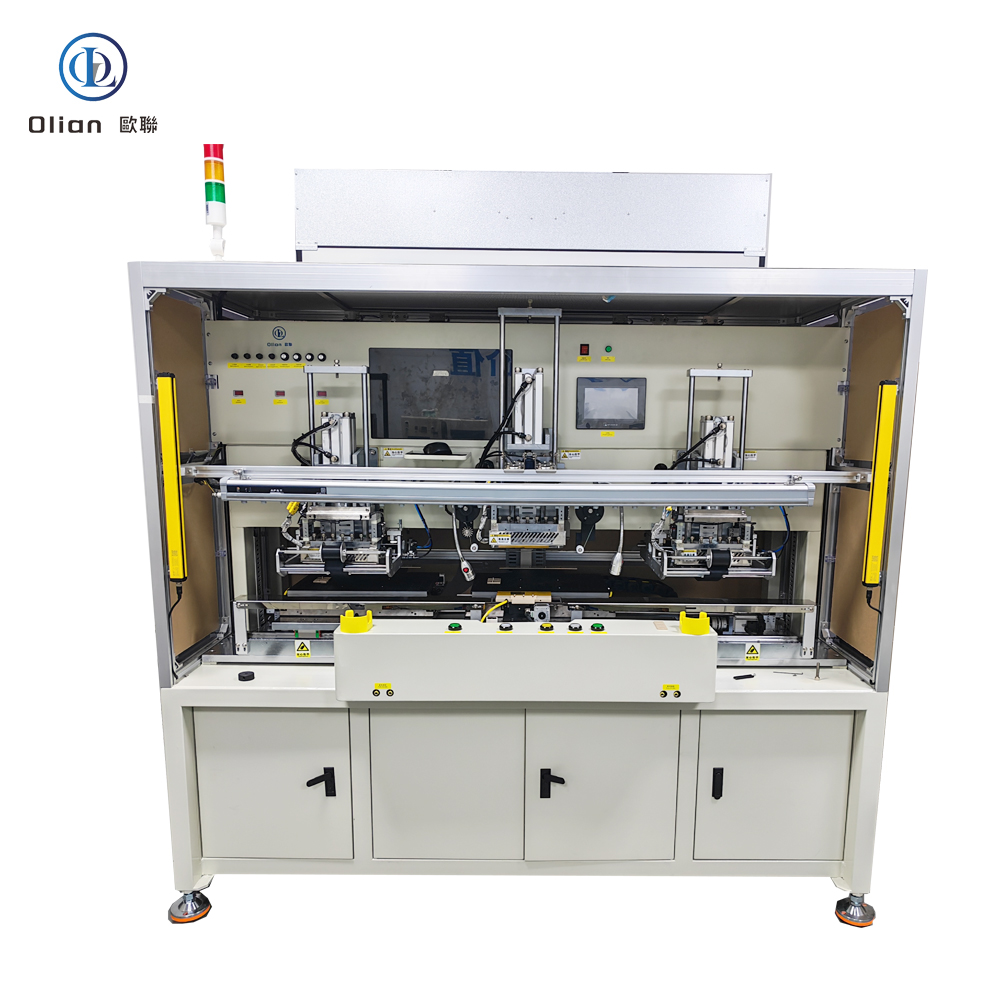
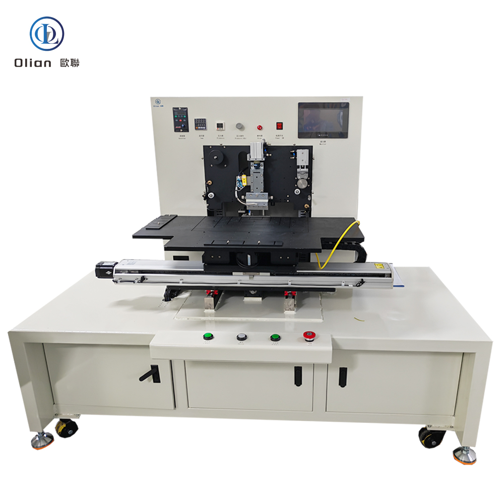

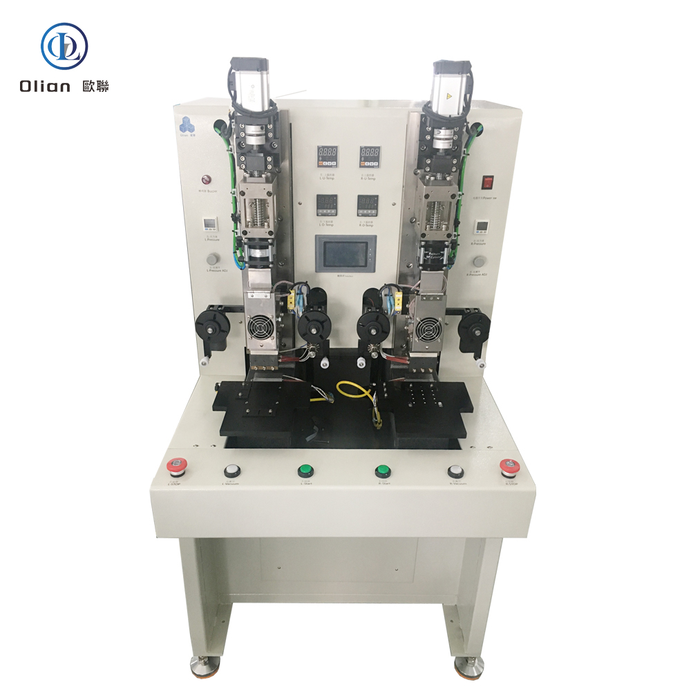
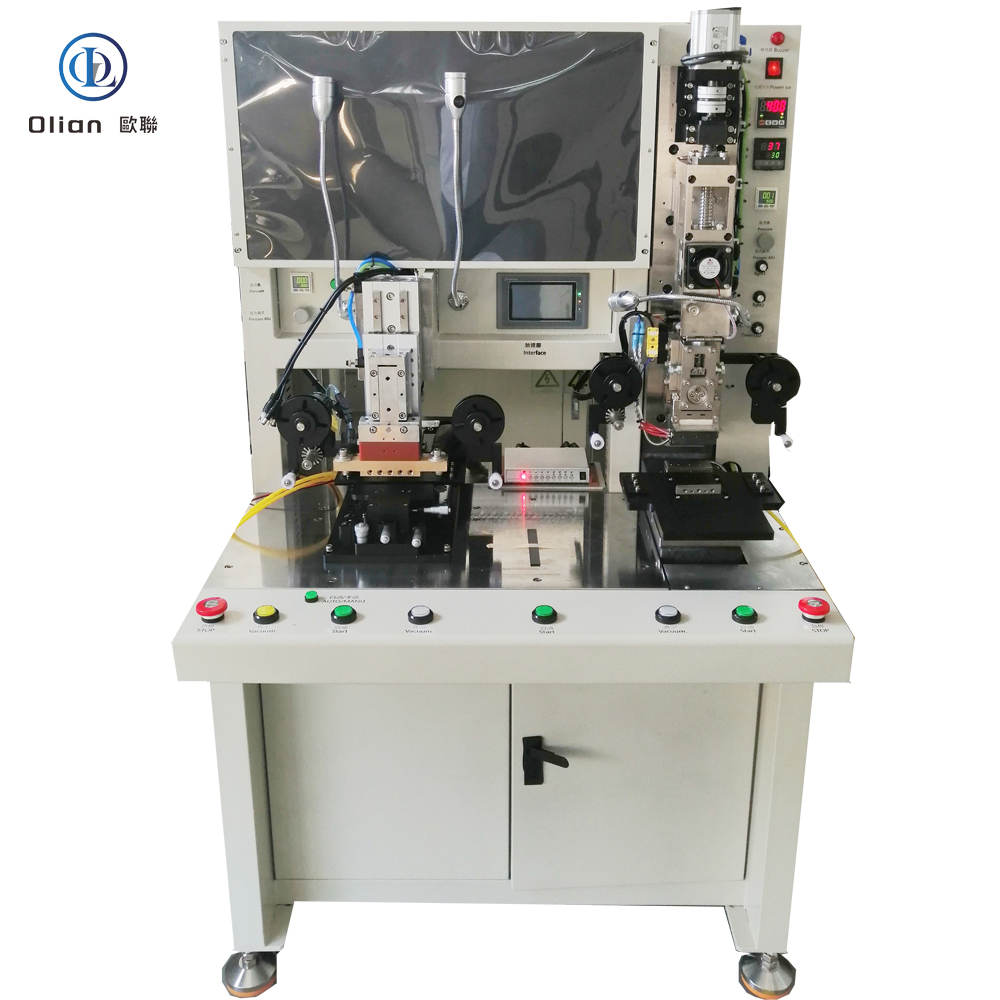

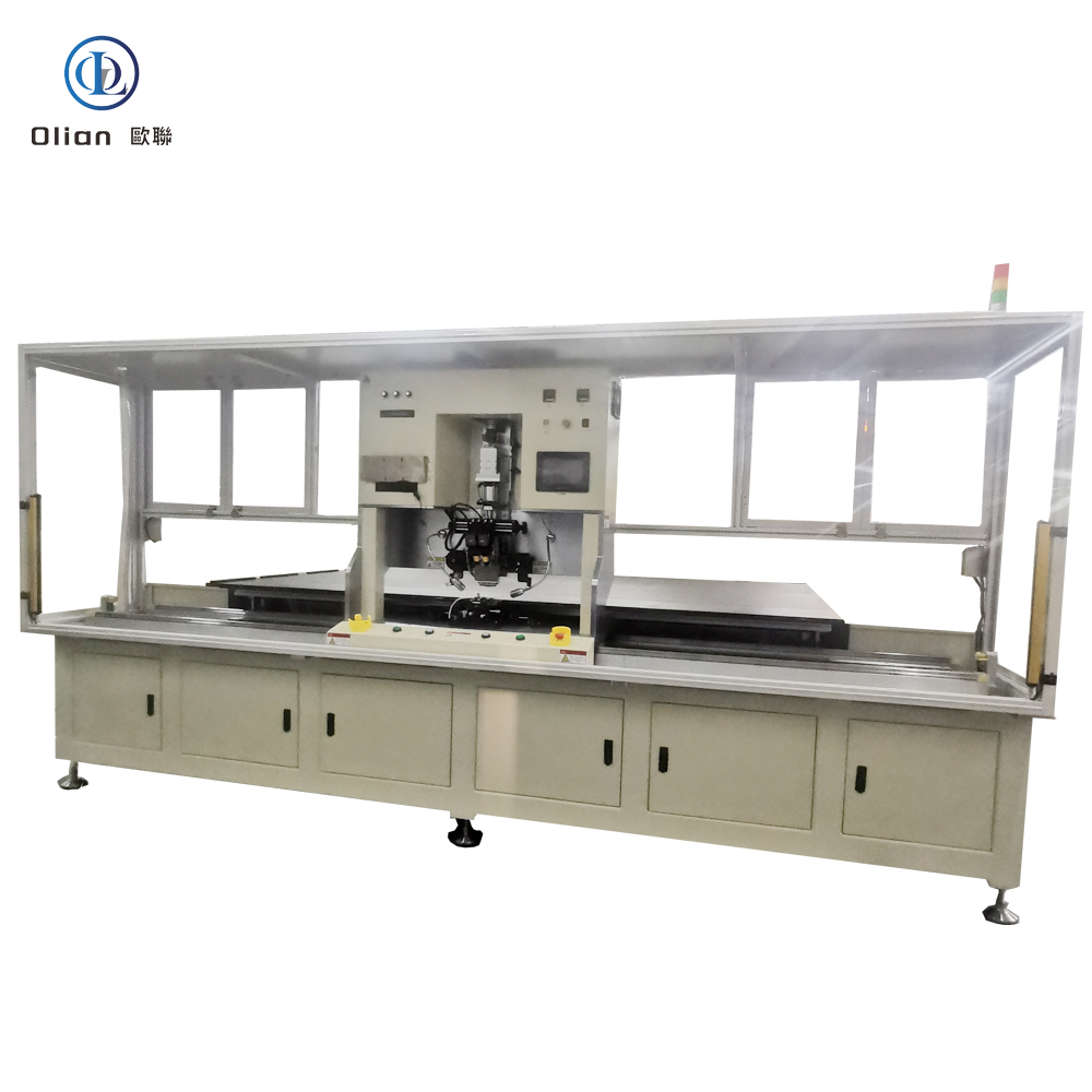


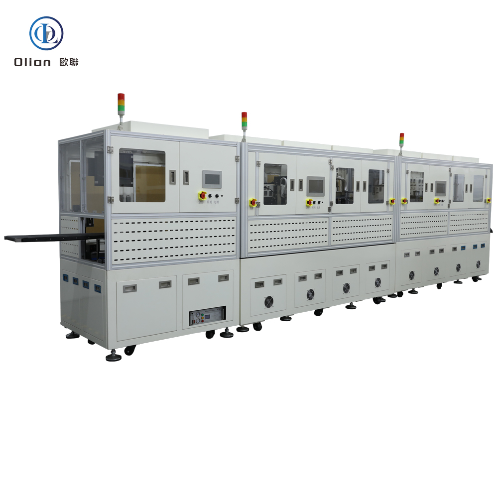
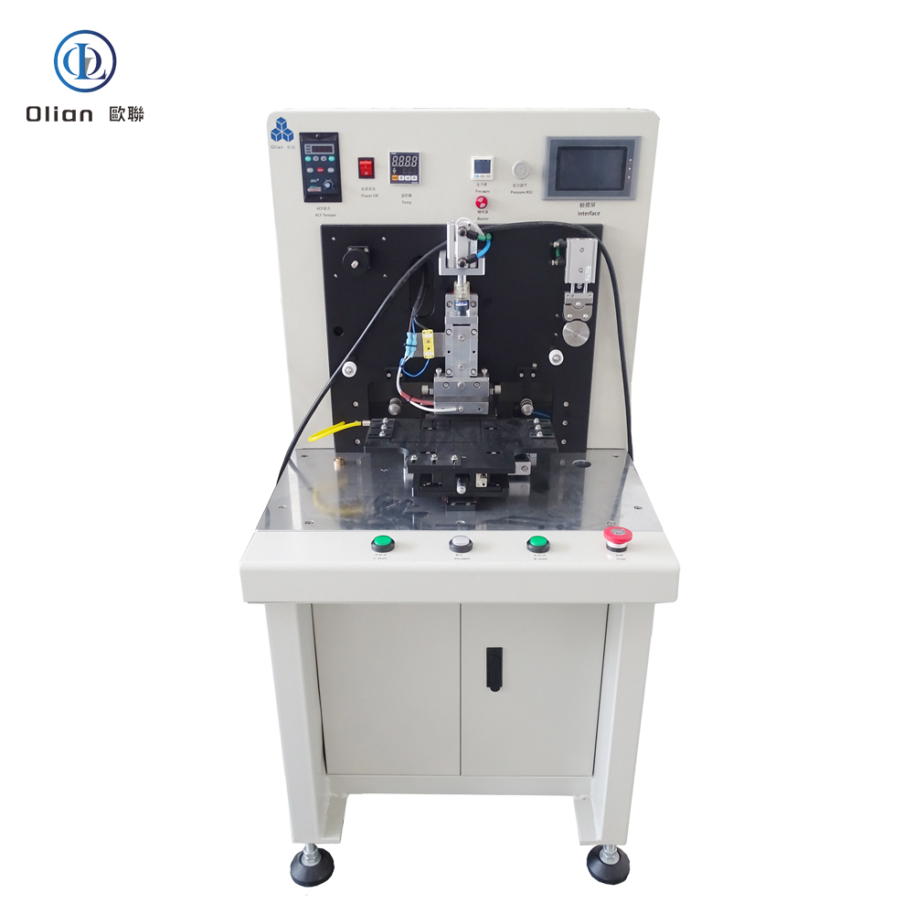
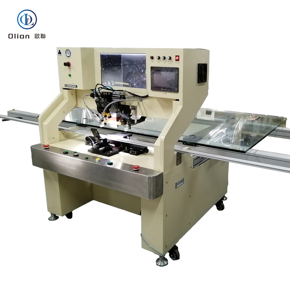
An ACF bonding machine is a servo-controlled pulse-heat press that laminates anisotropic conductive film onto a substrate, then bonds a second component—IC, flex, COF, or glass—using precisely programmed temperature, pressure, and time.
The goal is electrical contact in the vertical direction only, eliminating short circuits laterally.
The same machine also reworks defective panels by removing the old film and rebonding a new piece, saving a $300 TV screen or a $150 phone OLED.
Modern platforms handle 1-inch wearables to 100-inch TVs with ±1 µm alignment, ±0.5 °C thermal stability, and 0.01 MPa force resolution.
ACF is a 25–45 µm epoxy film loaded with 3–10 µm conductive spheres—nickel, gold-coated plastic, or copper-silver alloy.
During bonding, heat softens the resin and pressure compresses spheres between opposing pads.
The sphere count per pad is statistically designed so that at least three particles touch, giving < 30 mΩ contact resistance vertically.
Because neighboring pads are 20–50 µm apart, lateral particle density is too low to create a leakage path (> 1 GΩ isolation).
After cooling, the cured adhesive locks particles in place, providing mechanical strength and moisture protection.
Bonding Head: Titanium alloy, diamond-lapped to 0.5 µm flatness, DLC-coated for anti-stick, lasts 200,000 cycles.
Pulse Heater: 600 W cartridge, embedded K-type thermocouple, ramp 200 °C/s, overshoot < 0.5 °C.
Force Loop: Voice-coil or servo motor, 24-bit encoder, 0.1 kg resolution, 2 ms response; active gravity cancellation for 25 µm glass.
Vision System: 12 MP global-shutter CMOS, telecentric lens, coaxial + side LED, sub-pixel edge detection repeatable to 0.2 µm.
Motion Stage: Cross-roller bearings, 0.05 µm linear encoder, feedback at 20 kHz, granite base with passive vibration isolation.
ACF Tape Unit: Stepper-driven feed, tungsten-steel cutter, anti-static vacuum hold-down, waste take-up spool.
Real-time Linux kernel guarantees < 1 ms jitter; PID temperature loop updated at 10 kHz.
Recipe manager encrypts parameters—temperature, pressure, time, ramp rate, cooling rate—per product QR code.
MES interface via OPC-UA uploads cycle data, resistance values, and images for full traceability.
AI predictor analyses heater resistance drift and forecasts failure 200 cycles in advance.
Remote VPN allows OEM engineers to debug without on-site visit, cutting downtime 30 %.
Consumer Electronics: Smartphone OLED, tablet LCD, laptop mini-LED, smartwatch flexible AMOLED.
TV & Signage: 32″–100″ 4K/8K LCD, QLED, mini-LED, curved and foldable screens.
Automotive: Instrument clusters, center-stack OLEDs, head-up displays, rear-seat entertainment.
Medical: Surgical monitors, diagnostic tablets, wearable ECG patches.
Industrial & Aerospace: Avionics displays, factory HMI panels, military rugged tablets.
ACF bonding machine, ACF bonder, anisotropic conductive film bonding machine, LCD ACF bonding, OLED ACF bonding, TV panel ACF repair, pulse heat ACF machine, constant temperature ACF bonding, COF ACF bonding, FPC ACF bonding, TAB ACF bonding, IC ACF bonding, 100 inch ACF bonding, 8K display ACF bonding, foldable phone ACF bonding, automotive ACF bonding, medical device ACF bonding, China ACF bonding machine, automatic ACF bonder, ACF bonding accuracy 1 micron, ACF bonding temperature 220 C, ACF bonding pressure 1 MPa, vertical conduction horizontal insulation, lead-free ACF bonding, ROHS compliant ACF bonding.
Copper-Core ACF: Cu-Ag particles cut material cost 50 % while keeping < 20 mΩ contact resistance.
Green Refrigerants: Closed-loop cooling replaces water with R1234ze, reducing carbon footprint 30 %.
AI-Driven Profiles: Neural networks auto-optimize temperature ramps for each glass type, pushing yield to 99.9 %.
Micro-LED Bridge: Same ACF platform bonds 20 µm × 20 µm micro-LED dies onto glass backplanes.
Roll-to-Roll ACF: Reel-fed film and die-bond-on-the-fly reach 3,000 UPH for smart-glass.
Cold-Laser Assist: Femtosecond laser pre-treats pads at room temperature, enabling 120 °C bond for heat-sensitive flexible OLED.
An ACF bonding machine is no longer a niche press—it is the critical gateway between microscopic IC bumps and macroscopic display glass.
By mastering sub-micron alignment, single-degree thermal control and real-time force feedback, the latest ACF bonders deliver sub-3-second cycles with 99.9 % yield and full Industry 4.0 traceability.
Whether you are a display OEM chasing 0.9 mm bezels, a TV repair center reworking panels, or a micro-LED start-up prototyping smart-glass, investing in an AI-enhanced, IoT-connected ACF bonding platform future-proofs your process.
A COP bonding machine is the hidden engine behind the ultra-narrow chins of foldable phones, curved smart-watches and dashboard OLEDs.
COP means “Chip On Pi” (or “Chip On Plastic”): the display driver IC is bonded to a flexible polyimide/plastic film, then the film—and the IC—are folded 180° underneath the screen so the bezel almost disappears.
The machine that executes this microscopic fold-and-bond must deliver sub-micron alignment, single-degree thermal control and gram-level force accuracy—all in a 3-second cycle.
Keywords: “COP bonding machine”, “Chip On Pi bonder”, “flexible OLED IC bonding”, “ACF COP machine”, “foldable phone bonding equipment”, “narrowest bezel bonding”
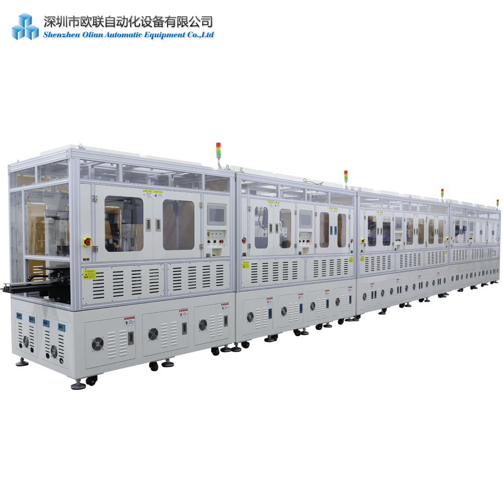
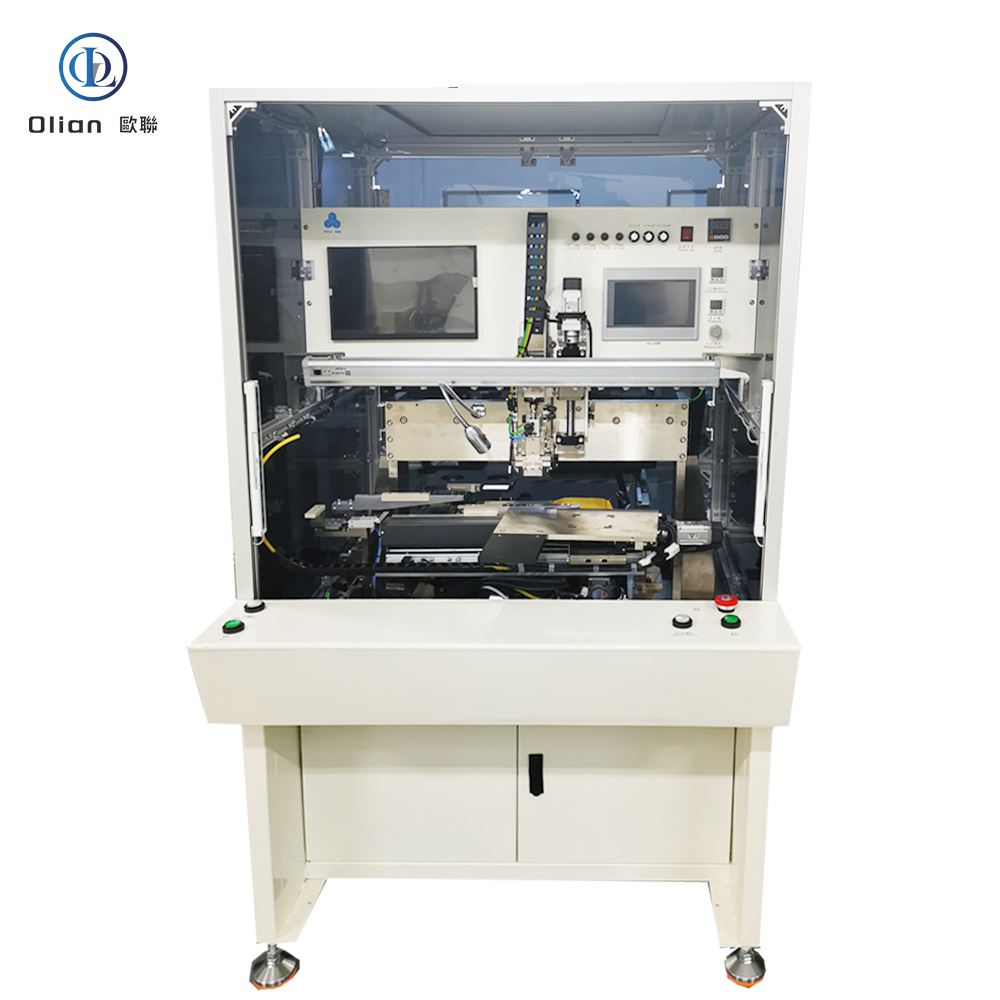
A COP bonding machine is a high-precision pulse-heat press that attaches a gold-bumped driver IC to a thin polyimide (Kapton) or specialty plastic substrate using anisotropic conductive film (ACF).
After bonding, the plastic tail is folded behind the active area, hiding the IC and releasing valuable “chin” space.
The same machine also reworks defective panels by removing the old IC and rebonding a new one, saving flexible OLED assembly.
Modern COP bonders achieve ±1 µm alignment, ±0.5 °C temperature stability and 0.1 kg force resolution on substrates as thin as 25 µm and as narrow as 0.8 mm.
COG (Chip-On-Glass) parks the IC on the glass itself, eating 3–4 mm of chin length.
COF (Chip-On-Film) moves the IC to a flex tail, but the tail still exits sideways before folding.
COP bonds the IC to a plastic film that can be folded 180° with a 0.2 mm bend radius, shrinking the bottom bezel to 0.9 mm and enabling 95 % screen-to-body ratios in flagship smartphones like iPhone X and OPPO Find X.
Plastic substrates also absorb thermal expansion mismatch better than glass, improving reliability in automotive and wearable applications.
Bonding Head: Titanium alloy, diamond-lapped to 0.3 µm flatness, plasma-nitrided to 70 HRC, anti-stick diamond-like-carbon (DLC) coating lasts 200,000 cycles.
Pulse Heater: 600 W cartridge, embedded K-type thermocouple, ramp rate 200 °C/s, overshoot < 0.5 °C.
Force Loop: Voice-coil actuator, 24-bit encoder, 0.1 N resolution, 2 ms response; active gravity cancellation for 25 µm substrates.
Vision System: 12 MP global-shutter CMOS, telecentric lens, coaxial LED + low-angle side light, sub-pixel edge detection repeatable to 0.2 µm.
Motion Stage: Cross-roller bearing, 0.05 µm linear encoder, servo feedback at 20 kHz, granite base with passive vibration isolation.
Software: Real-time Linux kernel, recipe encryption, SECS/GEM, OPC-UA, MES traceability, AI predictor for heater life.
Smartphones & Tablets: iPhone, Galaxy Fold, Huawei Mate X bond display driver and touch MCU on COP tail to achieve 0.9 mm chin
.
Wearables: Apple Watch, Xiaomi Band use COP to fold IC under OLED, creating curved edge with zero bezel.
Automotive: Curved instrument clusters and 15 inch OLED infotainment displays rely on COP for thermal cycling survival from −40 °C to +105 °C.
Medical: Flexible diagnostic patches and surgical monitors demand biocompatible polyimide and COP bonding.
Industrial & Military: Rugged handhelds and avionics displays exploit COP for shock, altitude, and fungus resistance per MIL-STD-810.
COP bonding machine, Chip On Pi bonder, flexible OLED IC bonding, ACF COP machine, foldable phone bonding equipment, narrowest bezel bonding, 0.9 mm chin bonding, polyimide bonding machine, 25 µm substrate bonding, pulse heat COP bonder, AI vision COP machine, IoT COP bonding, automotive COP bonding, wearable display bonding, micro-bump 12 µm bonding, lead-free COP bonding, ROHS compliant COP, China COP bonding machine, automatic COP bonder, COP vs COG vs COF comparison.
AI Predictive Alignment: Neural networks pre-heat the stage and compensate for polyimide shrinkage, pushing accuracy to ±0.5 µm.
IoT Yield Analytics: Every bond uploads temperature, force, and resistance curves; machine-learning spots heater degradation 200 cycles before failure.
Copper-Core ACF: Cu-Ag particles replace pure gold, cutting material cost 50 % while keeping < 20 mΩ contact resistance.
Cold-Laser Fold Assist: Femtosecond laser pre-scores the plastic, enabling 90° fold with 50 µm radius and zero trace damage.
Roll-to-Roll COP: Reel-fed polyimide and die-bond-on-the-fly reach 3,000 UPH for micro-LED smart-glass.
Green Refrigerants: Closed-loop cooling replaces water with R1234ze, reducing carbon footprint 30 %.
A COP bonding machine is no longer a niche flex-circuit tool—it is the critical enabler for foldable OLED, zero-bezel wearables and curved automotive clusters .
By mastering sub-micron alignment on 25 µm plastic, pulse-heat control within half a degree and real-time force feedback, the latest COP bonders deliver sub-3-second cycles with 99.97 % yield and full Industry 4.0 traceability.
Whether you are a display OEM chasing a 0.9 mm chin, a foldable-phone refurbisher OLED modules, or a micro-LED start-up prototyping smart-glass, investing in an AI-enhanced, IoT-connected COP bonding platform future-proofs your process .
Shenzhe Olian offer all kinds of COF Bonding machines, semi automatic COP bonding machines, Fully automatic COP bonding machines. Welcome you visit us!
COG bonding machine
A COG bonding machine is the micro-surgical robot of the display world.
COG—Chip-On-Glass—means the bare driver IC is flipped, aligned, and permanently fused directly to the glass substrate of an LCD, OLED, or mini-LED panel.
Because the chip sits on the glass instead of a flexible circuit, bezels shrink, signal paths shorten, and phones, tablets, laptops, TVs, automotive clusters, and medical monitors become thinner, lighter, and more reliable.
High-value keywords: “COG bonding machine”, “Chip on Glass bonder”, “LCD IC bonding equipment”, “ACF COG machine”, “pulse heat COG bonder”, “narrow bezel bonding”, “smartphone display bonding”, “automotive COG bonding”, and many more.
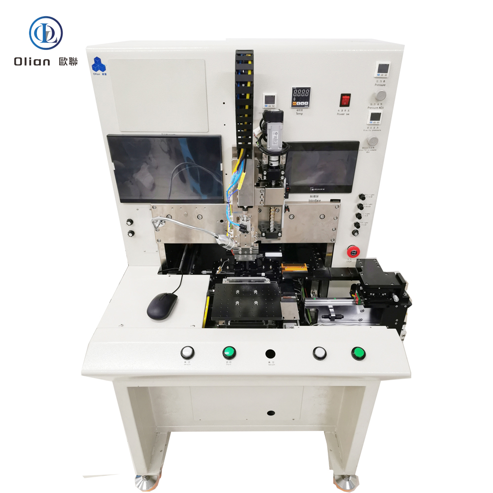
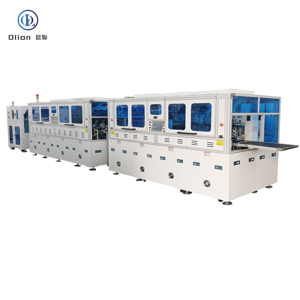
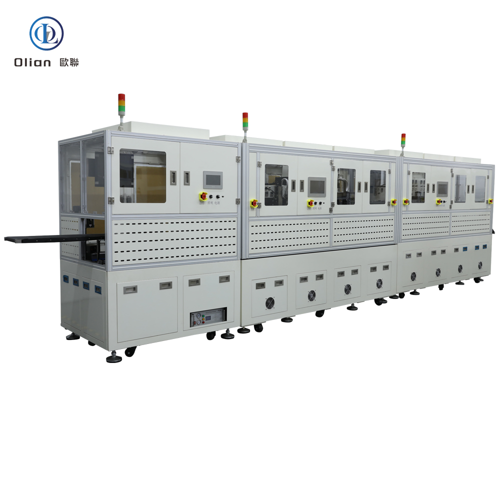
A COG bonding machine is a high-precision pulse-heat press that picks up a gold-bumped driver IC, places it face-down on a glass substrate, and bonds it through anisotropic conductive film (ACF) in one three-second cycle.
The film contains 3–5 µm nickel or gold-coated plastic spheres.
Heat and pressure trap particles between IC bump and glass pad, creating thousands of vertical contacts while remaining insulated laterally.
The result is a permanent, flexible, lead-free interconnect that survives −40 °C to +85 °C thermal shock, 1,000-cycle bend tests, and 95 % humidity at 65 °C for 1,000 h.
Modern COG bonders achieve ±1 µm alignment, ±0.3 °C temperature stability, and 0.1 kg force resolution on panels from 1 inch smartwatches to 17 inch automotive displays.
COG eliminates the flexible printed circuit entirely.
Signal length from IC to pixel column drops 50 %, reducing EMI at 120 Hz and 240 Hz refresh rates.
Because the IC overhangs only 0.3 mm beyond the active area, bezels shrink to 0.9 mm, enabling edge-to-edge smartphones and seamless multi-screen video walls.
Cost drops: no flex, no connector, less copper.
Yield rises: fewer solder joints, no FPC misalignment.
Rework is possible: a laser can remove a defective IC and rebond a new one in under two minutes
Bonding Head: Titanium alloy, diamond-lapped to 0.5 µm flatness, plasma-nitrided to 70 HRC, anti-stick coating lasts 100,000 cycles.
Heater Cartridge: 400 W, ramp rate 150 °C/s, embedded K-type thermocouple accuracy ±0.3 °C.
Force Actuator: Voice-coil or servo motor with 16-bit encoder, 0.1 N resolution, 5 ms settling time.
Vision System: 12 MP CMOS cameras, telecentric lens, coaxial LED ring light, sub-pixel edge detection repeatable to 0.2 µm.
Motion Stage: Cross-roller bearing, 0.05 µm linear encoder, feedback loop at 10 kHz, vibration isolation granite base.
Software: Windows real-time kernel, recipe encryption, SECS/GEM for semiconductor fabs, OPC-UA for Industry 4.0 dashboards.
Smartphones & Tablets: COG bonds the display driver and touch controller in iPhone, Galaxy, and iPad lines, enabling 1 mm side bezels.
Laptops & Monitors: 240 Hz gaming panels use COG to cut latency and electromagnetic noise.
Automotive: Curved instrument clusters and 12.3 inch center stacks rely on COG for vibration resistance from −40 °C to +105 °C.
TV & Signage: 4K and 8K LCD/mini-LED TVs bond source drivers on both top and bottom edges; COG shrinks frame width to 6 mm.
Medical: Surgical displays and portable ultrasound units demand zero flex cable failure; COG delivers 99.97 % reliability.
Industrial & Military: Avionics and factory HMI panels use COG for shock, altitude, and fungus resistance
COG bonding machine, Chip on Glass bonder, LCD IC bonding equipment, ACF COG machine, pulse heat COG bonder, narrow bezel bonding, smartphone display bonding, automotive COG bonding, TV driver IC bonding, 8K display bonding, micro-bump bonding, flip chip glass bonding, lead-free IC bonding, ROHS compliant bonding, China COG bonding machine, automatic COG bonder, COG vs COF comparison, COG bonding accuracy 1 micron, COG bonding temperature 220 C, COG bonding pressure
AI Predictive Alignment: Neural networks pre-heat the stage to cancel thermal expansion, pushing accuracy to ±0.5 µm.
IoT Yield Analytics: Every bond uploads temperature, force, and resistance to the cloud; big data predicts heater failure one week early.
Green ACF: Copper-core particles replace gold, cutting material cost 50 % while maintaining < 30 mΩ contact resistance.
Cold-Laser Assist: Femtosecond laser cleans bumps at room temperature, allowing polyimide-friendly 120 °C bond profiles.
Micro-LED Bridge: Same COG platform bonds 20 µm × 20 µm micro-LED dies onto glass backplanes for next-generation emissive displays.
Servo-Hydraulic Hybrid: Delivers 80 kg force for 100″ TV panels while keeping 1 µm position accuracy.
A COG bonding machine is no longer a niche tool—it is the beating heart of every slim-bezel smartphone, every 240 Hz gaming monitor, and every curved automotive cluster you will touch .
By mastering sub-micron alignment, single-degree thermal control, and ton-class force feedback, the latest COG bonders deliver 3-second cycles with 99.97 % yield and full Industry 4.0 traceability.
Whether you are a display OEM chasing 0.9 mm bezels, a TV repair center , or a micro-LED start-up prototyping next-gen emissive screens, investing in an AI-enhanced, IoT-connected COG bonding platform future-proofs your process.
Shenzhen Olian is professional in design & assembly&sales&service for all kinds of COG bonding machine. Welcome to feel free visit us in shenzhen of China.
A COF bonding machine is the quiet hero inside every ultra-slim TV, foldable phone, and curved automotive cluster. COF means Chip-On-Film: a bare driver IC is bumped, flipped, and bonded to a thin polyimide ribbon that later folds tightly behind the glass. The machine that performs this microscopic wedding must deliver micron-level alignment, single-degree temperature control, and ton-class pressure accuracy—all in under four seconds. Below you will find a dense but readable walk-through of definition, working principle, core parts, applications, specifications, trends, and maintenance keywords such as “COF bonding machine”, “Chip on Film bonder”, “LCD COF repair equipment”, “pulse heat COF machine”, and “4K TV bonding tool”.
A COF bonding machine is a machine that attaches COFs to LCD OLED MINILED MICROLED FPC FFC PCB Ceramic and silicone substrates with ACF tapes. The bond must conduct vertically between bump and copper track yet stay insulated horizontally between neighboring 20 µm traces. When the film later folds behind the panel, the IC sits in the narrow bezel instead of on the glass, enabling edge-to-edge pictures in smartphones, OLED TVs, and 8K monitors. The same machine also reworks defective TV panels by removing the old IC and rebonding a new one, saving hundreds of dollars per screen.
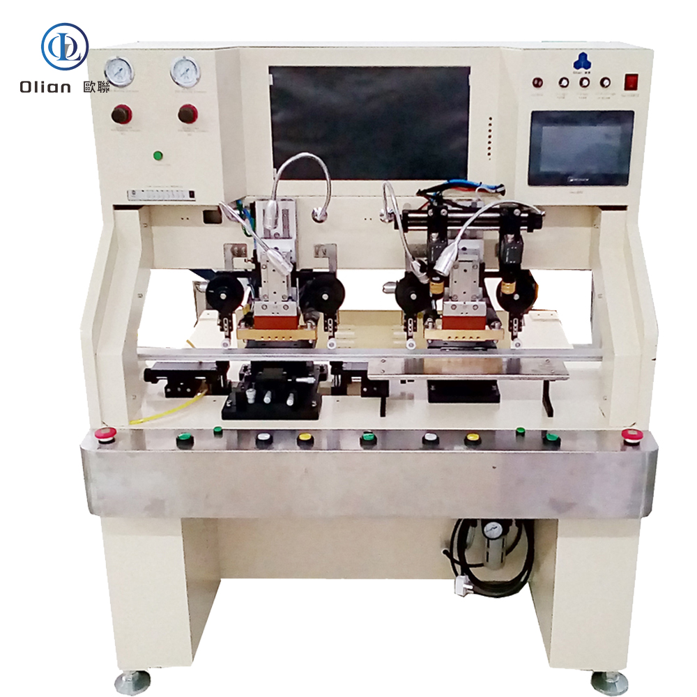
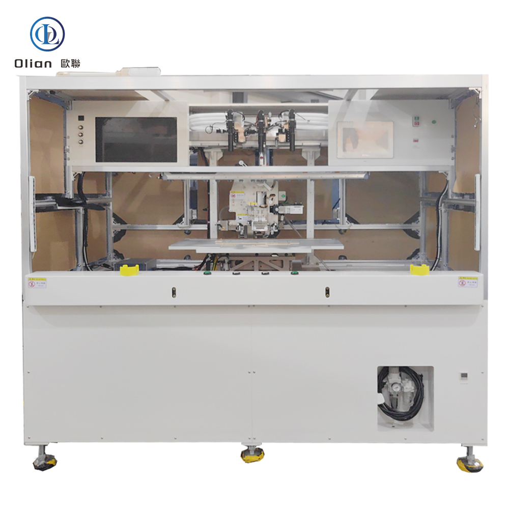
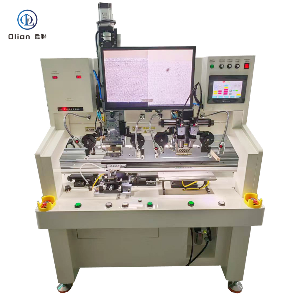
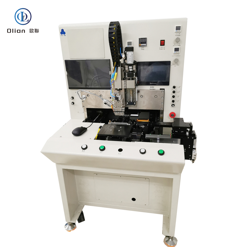
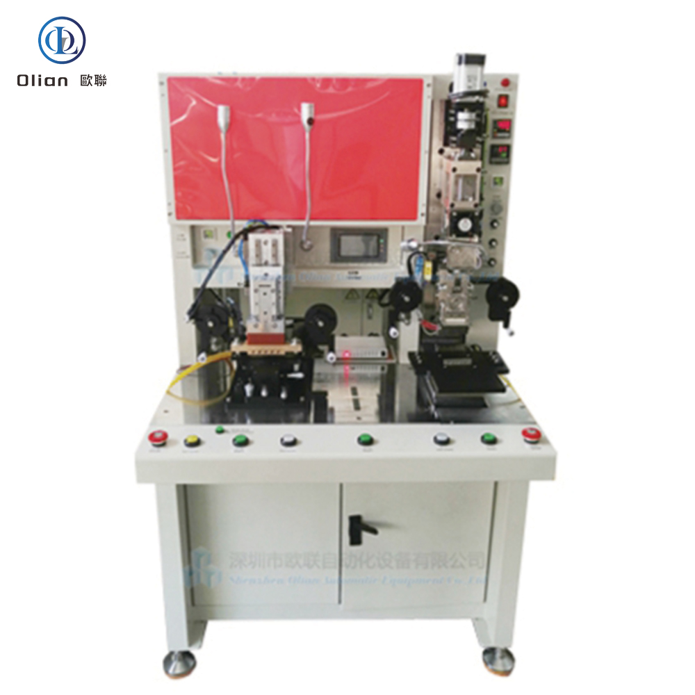
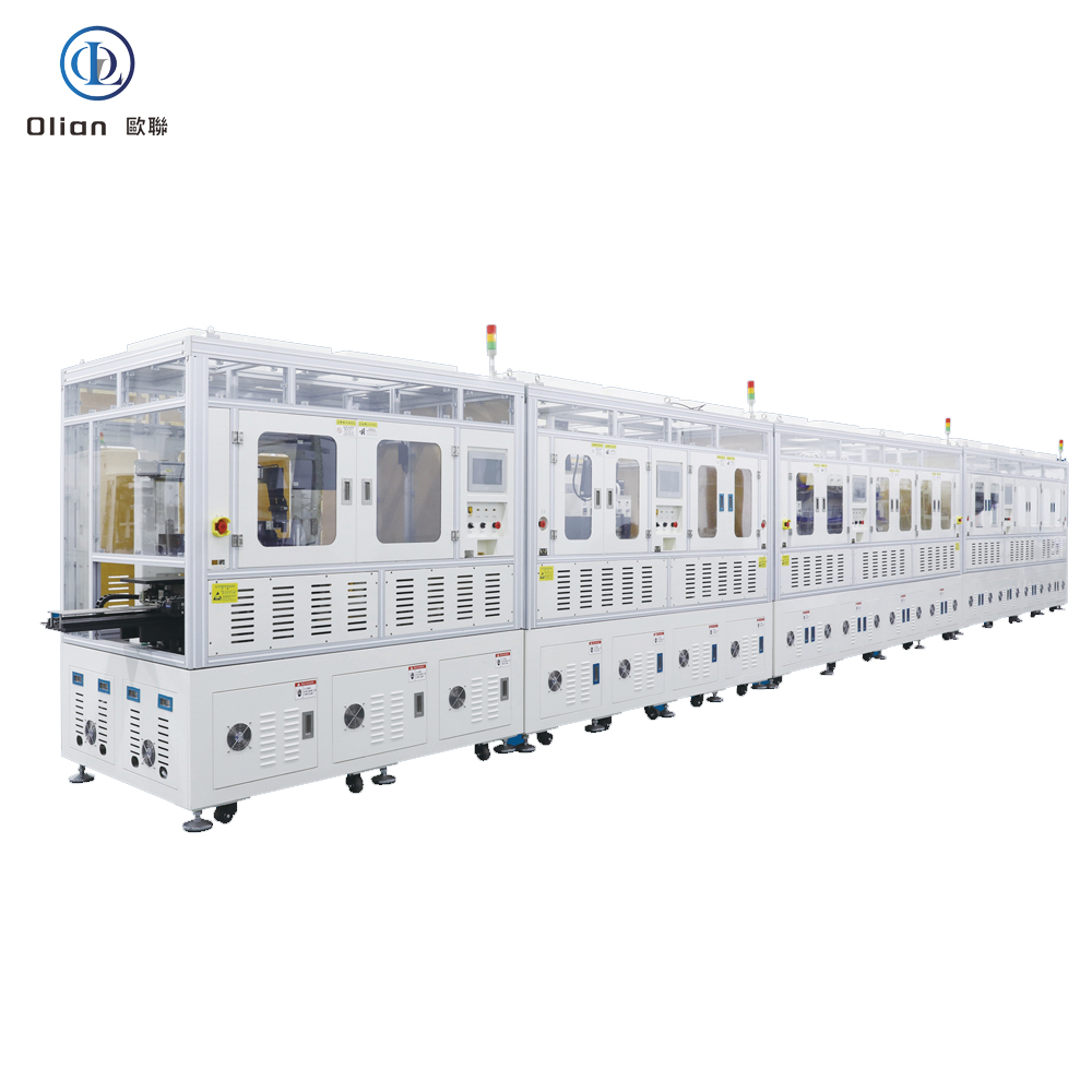
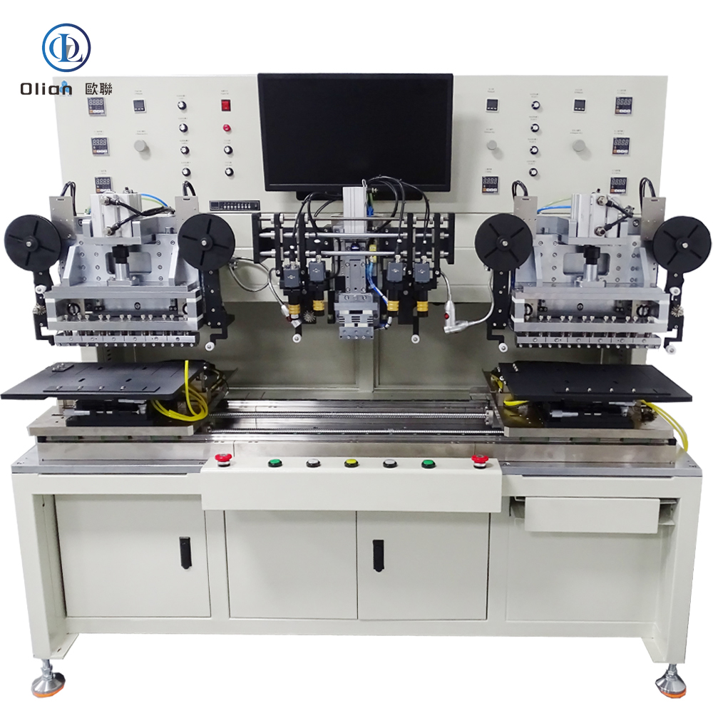
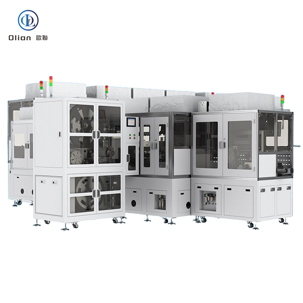
Consumer Electronics: Smartphone OLED, tablet LCD, laptop mini-LED, smartwatch flexible AMOLED.
TV Manufacturing: 32″–100″ 4K/8K panels, 120 Hz and 144 Hz gaming monitors, curved screens.
Automotive: Instrument clusters, center-stack touch displays, head-up projection films.
Medical: High-resolution diagnostic monitors, surgical displays that require narrow bezels for sterile integration.
Industrial: Human-machine interfaces, outdoor kiosks, aviation seat-back entertainment.
This article naturally embeds high-value phrases: COF bonding machine, Chip on Film bonder, ACF bonding equipment, pulse heat bonding, LCD repair COF, TV panel bonding machine, 4K 8K display bonding, flexible film IC bonding, micro-bump bonding, narrow bezel technology, OLED COF bonding, foldable display bonding, laser COF repair, bonding accuracy 1 micron, freezing separator alternative, lead-free bonding, ROHS compliant bonding, China COF bonding machine, automatic COF bonder, COF vs COG comparison.
AI-Driven Alignment: Deep-learning vision predicts thermal drift and pre-corrects position, pushing accuracy below 0.5 µm.
IoT Monitoring: Each head uploads temperature, pressure, and resistance curves to the cloud; machine-learning spots early heater failure and schedules maintenance before scrap occurs.
Green ACF: New conductive particles use copper-silver alloy instead of pure gold, cutting material cost 40%.
Roll-to-Roll Bonding: Reel-fed film and waffle-pack ICs enable continuous bonding for micro-LED transfer, reaching 2000 units/h.
Cold Laser Assist: Femtosecond laser pre-treats the polyimide surface, lowering required bonding temperature to 120 °C, ideal for heat-sensitive flexible OLED.
Servo-Hydraulic Hybrid: Combines speed of servo presses with force stability of hydraulics for 100″ TV COF where 80 kg force is needed.
A COF bonding machine is the critical enabler for ultra-narrow bezels, high refresh rates, and foldable designs. By mastering micron alignment, pulse-heat control, and real-time force feedback, manufacturers can bond driver ICs on flexible film at speeds exceeding one chip every four seconds while maintaining reliability across −40 °C to +85 °C. Whether you run a high-volume TV line or a boutique phone refurbishing shop, investing in the latest AI-enhanced, IoT-connected COF bonding platform future-proofs your process for 8K, micro-LED, and beyond.
An LCD repair machine is a precision system that fixes cracked glass, failed TAB bonds, open ITO lines, color lines, and backlight problems in televisions, laptops, tablets, smartphones, and industrial monitors. Instead of throwing expensive panels away, service centers use these machines to restore original performance at component level. The following long-form article explains every angle of the technology so Google can easily index the keywords “LCD repair machine”, “TV panel repair equipment”, “laser LCD repair”, “TAB bonding machine”, “COF bonding machine”, “LCD freezing separator”, and related phrases.
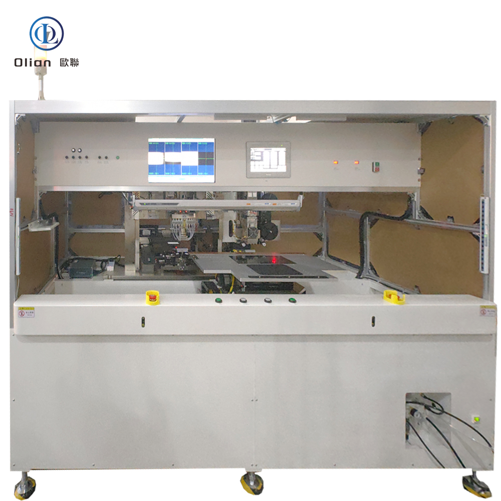
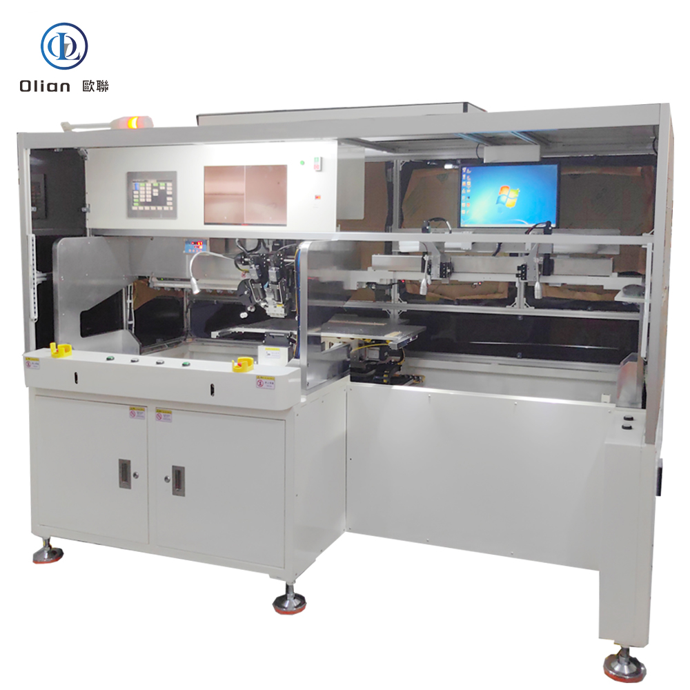
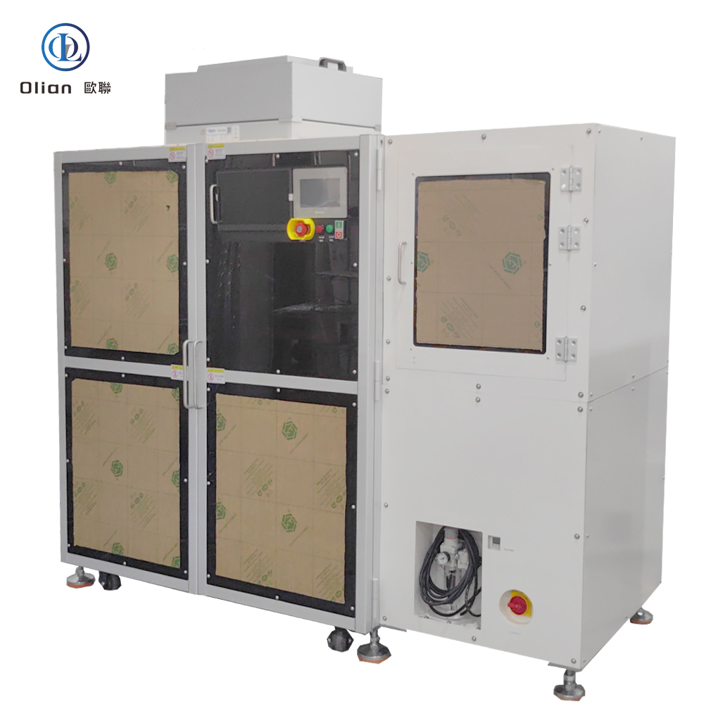
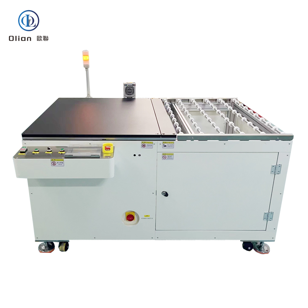
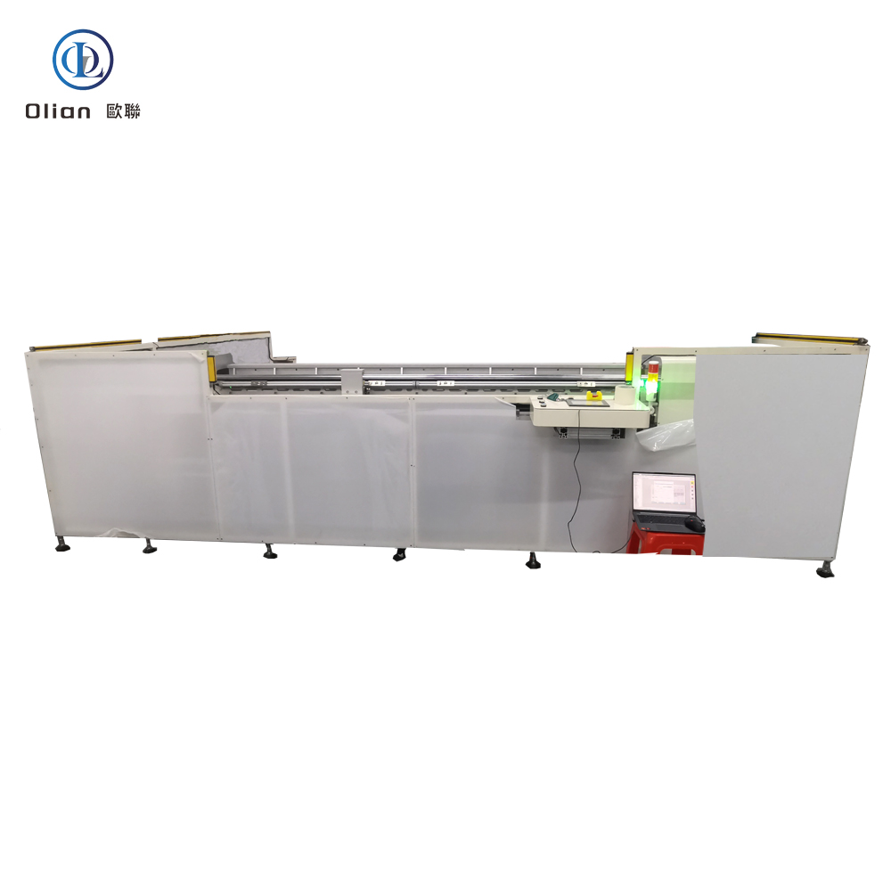
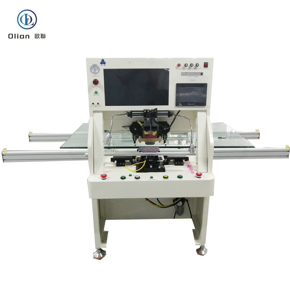
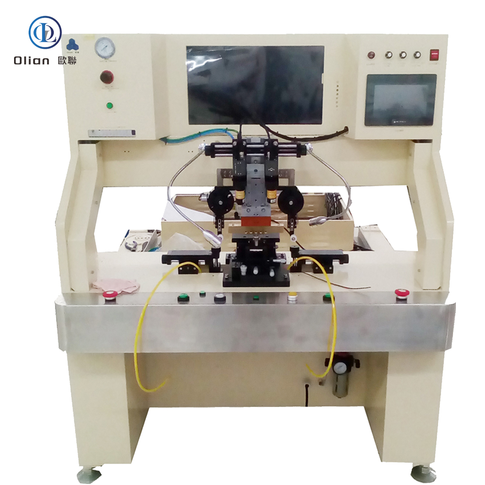
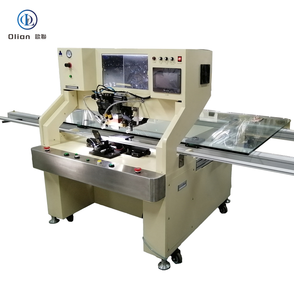
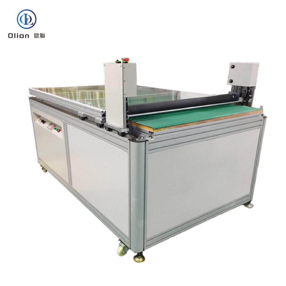
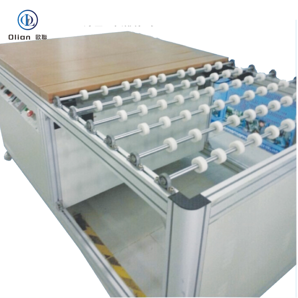
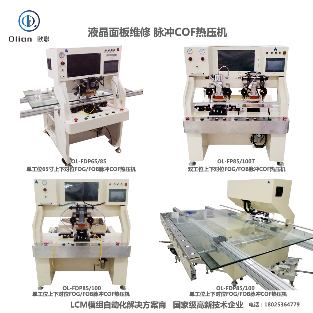
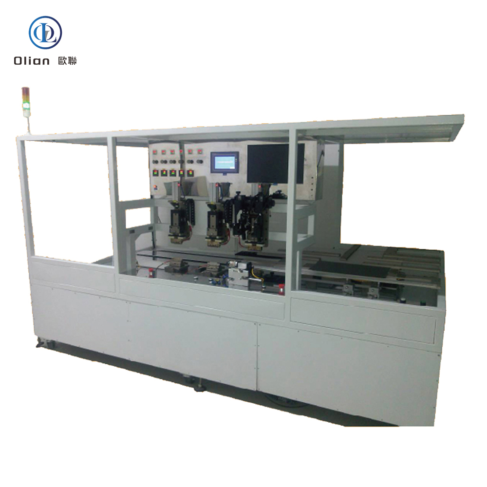
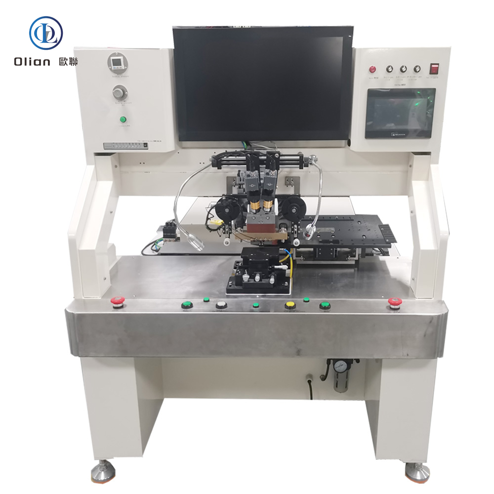
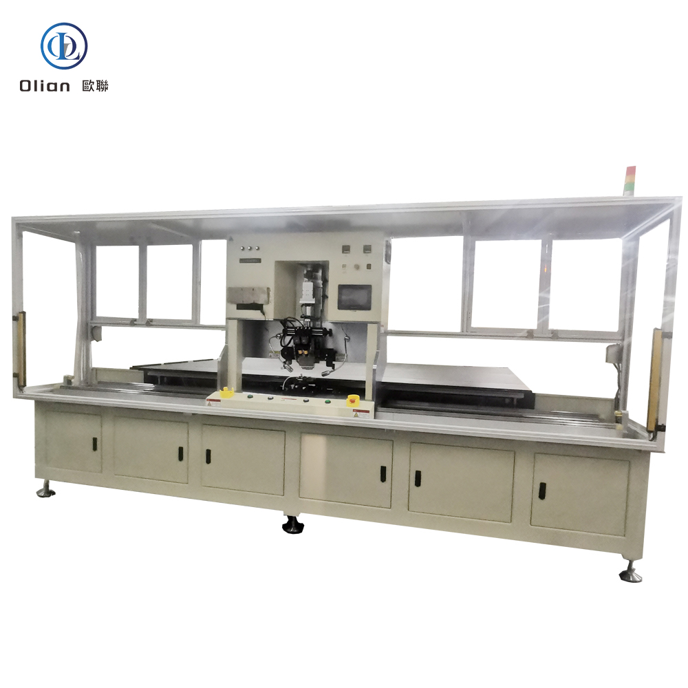
An LCD repair machine is a collective name for several modules that separate, clean, bond, test, and sometimes laser-trim LCD glass. Each module targets a specific fault: outer glass cracks, polarizer scratches, flex cable delamination, driver IC failure, or internal short/open circuits inside the glass. Professional workshops combine these modules into one production line to handle 5″, 10″, 32″, 55″, 65″, 75″, even 100″ panels with the same daily throughput. The process is lead-free, ROHS friendly, and generates far less e-waste than replacing the whole display.
The freezing separator repairs outer glass damage on phones and tablets. It cools the assembly to minus 140 °C with liquid nitrogen or compressed refrigerant. The low temperature embrittles the OCA glue so a steel wire slides between cover glass and the sensitive OLED or LCD underneath without force. After separation, the machine warms to room temperature, allowing easy pick-up of broken glass and leftover glue removal. The same cabinet can process 30–50 screens per hour with almost zero breakage when operators follow the correct recipe
.
A lower-cost alternative for shops that do not want liquid nitrogen. The hot plate heats the screen to 80–90 °C, while a vacuum chuck keeps the glass flat. A thin cutting wire then separates the glass. The method is slower but adequate for entry-level phone repair businesses.
TAB (tape-automated bonding) and COF (chip-on-film) bonding machines repair flex cable failures in TV panels. A pulse-heated titanium head presses the flex against the LCD pad through anisotropic conductive film (ACF). The head ramps to 180–220 °C in two seconds, holds ±0.3 °C accuracy, then cools quickly to solidify the adhesive while conductive particles create vertical conductivity only. Modern models bond 4K/8K panels up to 100 inches with 1.5 µm alignment accuracy
.
Laser systems fix internal glass defects such as bright lines, dark lines, half-lines, dot defects, short circuits, or ITO opens. A Nd:YAG or fiber laser fires microsecond pulses through a microscope objective to cut or link redundant bus lines inside the panel. Dual-wavelength machines (1064 nm + 532 nm) handle both metal and transparent oxide layers. Spot size can be as small as 3 µm, so the repair is invisible to the naked eye
.
After glass replacement or laser trimming, a new polarizing film must be laminated without dust or bubbles. The laminator uses a rubber roller in a Class-100 clean chamber to apply even pressure. A subsequent autoclave heats the stack to 45 °C under 0.4 MPa for 20 minutes to eliminate micro-bubbles.
LCD repair machine, TV panel repair equipment, laser LCD repair, TAB bonding machine, COF bonding machine, ACF bonding equipment, LCD freezing separator, polarizer laminator, LCD refurbishing machine, smartphone screen repair tools, 4K panel bonding, 100 inch LCD repair, internal line repair laser, ITO open repair, vertical line fix, horizontal line fix, dot defect removal, pulse heat bonding, fine-pitch bonding, lead-free LCD repair, ROHS compliant repair, e-waste reduction, sustainable display repair.
AI-driven vision will auto-select laser cut or link paths, reducing technician training time. IoT modules will send yield data to cloud dashboards for predictive maintenance. Green refrigerants will replace liquid nitrogen in freezing separators, cutting operating cost by 30%. Roll-to-roll ACF will enable continuous bonding of ultra-wide 110″ panels. Micro-LED hybrid displays will adopt the same laser micro-machining platforms, extending the machine’s useful life well into the next decade.
An LCD repair machine is no longer a single-purpose tool; it is a strategic investment that restores value to damaged displays, supports environmental goals, and delivers rapid return on investment across smartphones, TVs, laptops, automotive, and industrial applications. By choosing the right combination of freezing separation, TAB/COF bonding, laser trimming, and polarizer lamination modules, service centers can handle virtually any LCD faults. Shenzhen Olian to be the LCD repair machine’s one stop supplier..