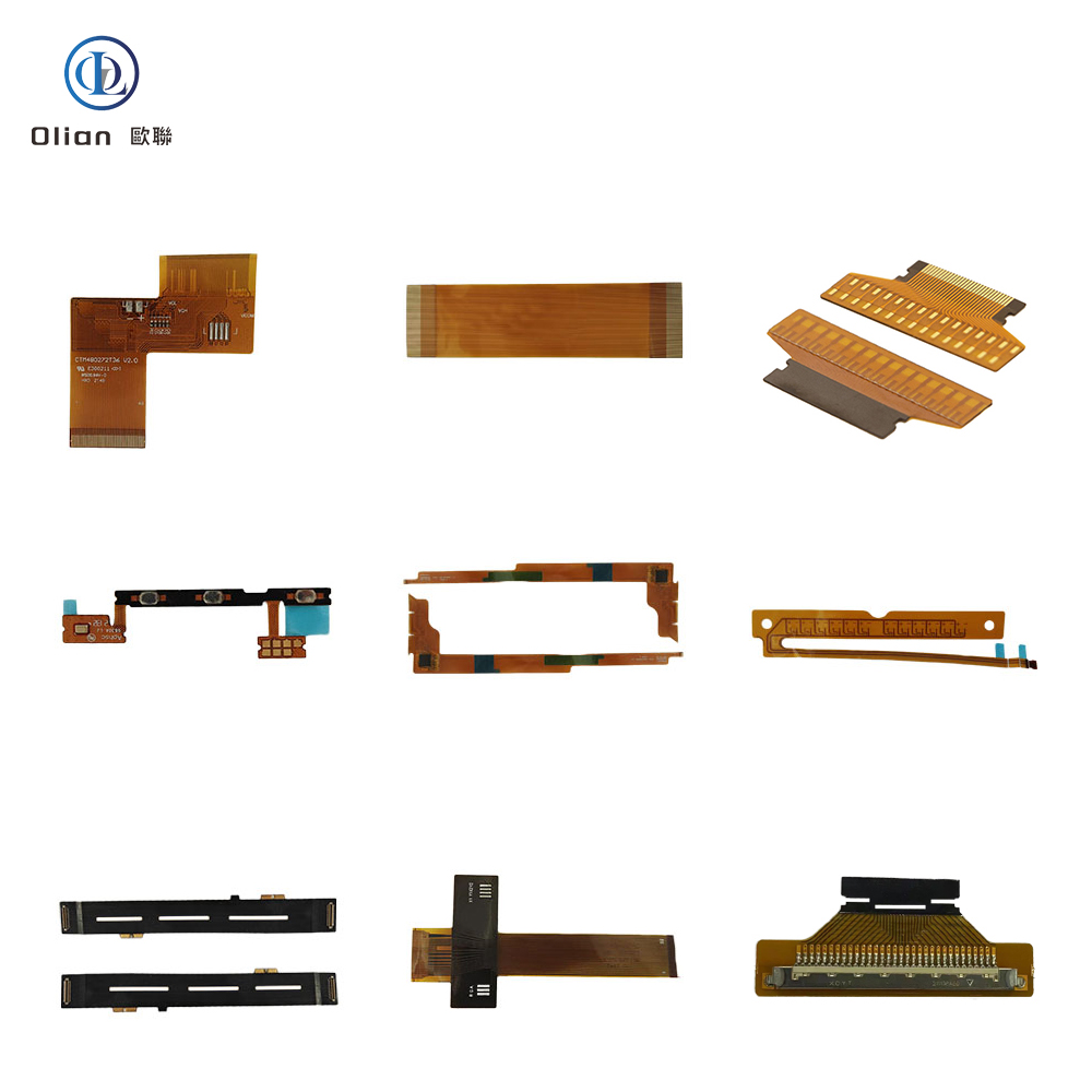
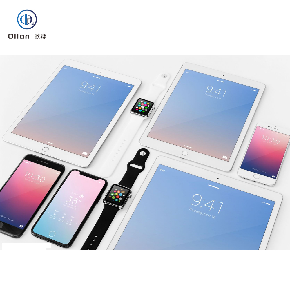
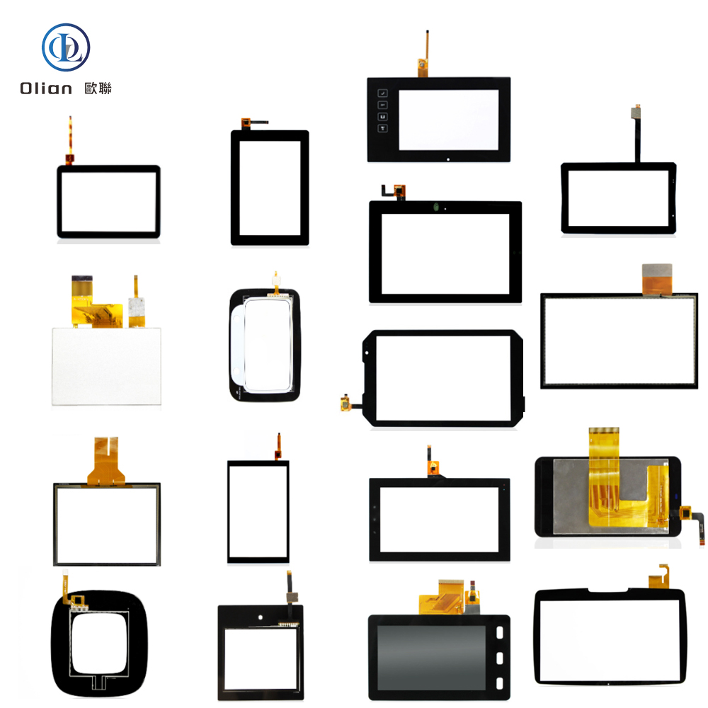
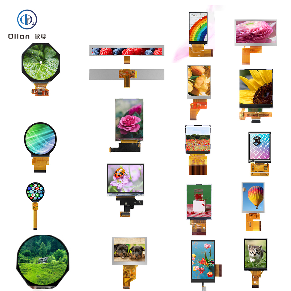
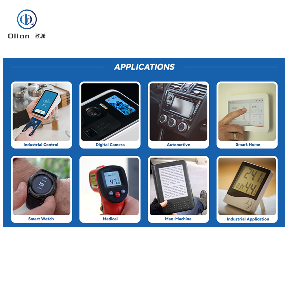
From smartphones and tablets to TVs and computers, thin displays have become integral to our modern lives.
The display technology has undergone an impressive evolution. ACF has been fundamental to advancing display technologies, from LCD to OLED and flexible OLED. Let’s explore how display technology has evolved and examine ACF’s vital contribution to this journey.
The development of liquid crystal displays (LCDs) and the contribution of ACF
The LCD story began in the 1960s with a breakthrough discovery: liquid crystals could be used to create visual displays.
This technology found its first commercial applications in calculators and wristwatches during the 1970s, before expanding to larger formats like laptops, TVs, and monitors in the 1990s.
In LCD’s evolution, the push toward thinner profiles and higher resolutions was paramount.
ACF proved instrumental in this development by providing reliable circuit connections.
The technology delivers not only ultra-thin connections but also ensures robust bonding, exceptional reliability, and effective electrical isolation between adjacent circuits.
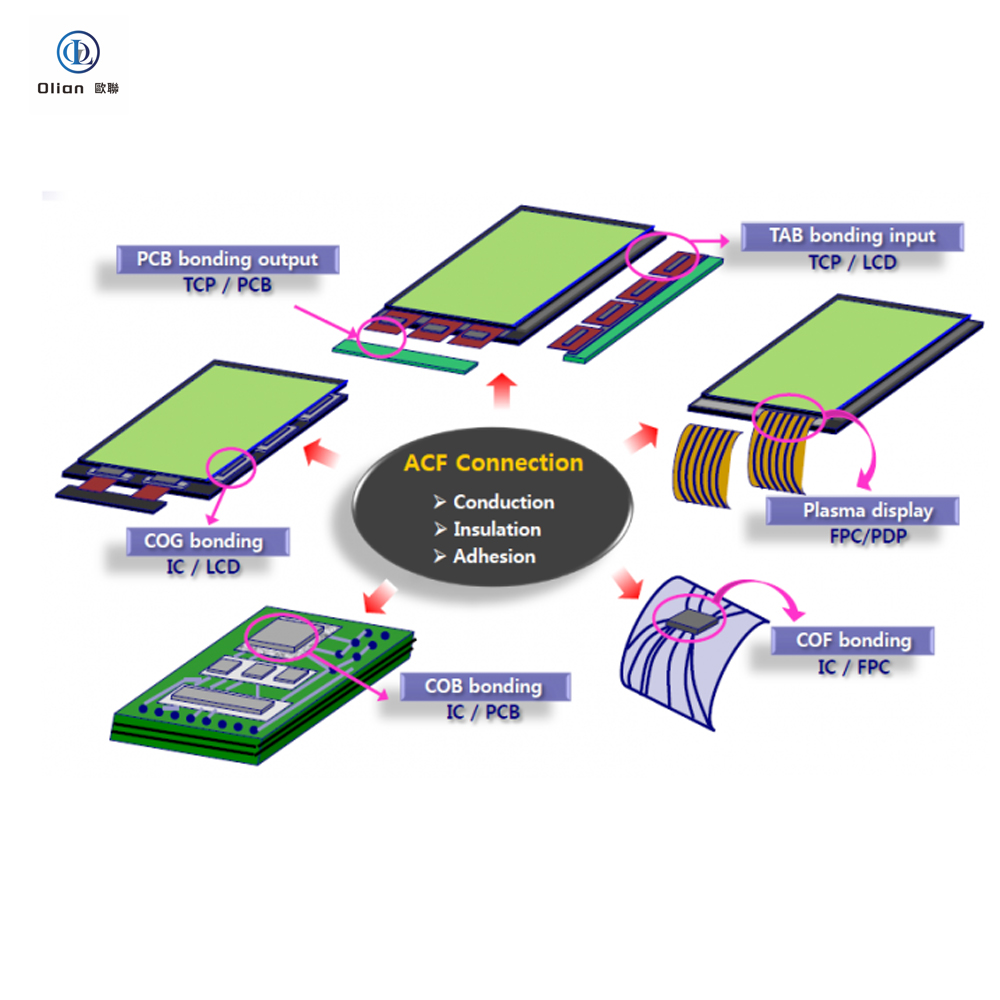
Its versatility extends to various substrates, enabling connections for Tape Carrier Package (TCP) and Chip on Film (COF) package signal outputs to displays, while also supporting Chip on Glass (COG) driver IC implementation.
The adoption of ACF has enabled higher resolutions through the miniaturization of circuits and contributed to thinner and lighter devices through the miniaturization of driver ICs.
LCD technology has developed rapidly since the discovery of the principles behind the use of liquid crystals for visual display. but it may not have been possible to achieve the modern thin and high-resolution displays without the evolution of ACF technology.
The emergence of OLED displays and the adaptation of ACF technology
As LCD technology matured, OLED emerged as the next generation of display technology.
After the Eastman Kodak Company announced the fundamental principles behind OLED in 1987, elements that emit their own light were used to achieve display technology that featured higher contrast than conventional LCD, wide viewing angles, thinness, and lightweight.
However, initial adoption was hampered by manufacturing costs and technical hurdles. Several factors contributed to OLED’s initially slow market penetration: prohibitive production costs, limited lifespan of blue organic electroluminescent elements, and image retention issues with static content.
Additionally, the complexity of OLED manufacturing processes and low yield rates presented significant challenges for mass production.
OLED technology made its breakthrough in the late 2000s, first appearing in small displays for smartphones and digital cameras as manufacturers overcame initial technical hurdles.
As the technology’s advantages became increasingly apparent, OLED displays expanded into large-screen TVs and flexible displays. Throughout this evolution, ACF technology adapted and advanced to accommodate OLED’s unique electrical properties and circuit designs.
Flexible OLED and ACF’s technical innovation: achieving Flex on Plastic (FOP) and Chip on Plastic (COP)
The advent of flexible OLED displays, utilizing polyimide substrates, marked a breakthrough in creating durable, highly flexible foldable displays.
While this technology opened new possibilities for flexible displays and wearable devices, it presented a significant challenge: maintaining reliable electrical connectivity with flexible substrates.
To address this challenge, innovative mounting technologies emerged, including FOP (mounting flexible FPC directly On Plastic) and COP (mounting hard IC On plastic substrate).
These solutions rely heavily on ACF technology to create secure connections between flexible plastic substrates and rigid driver ICs. ArrayFIX, represents a significant advance in this field. This particle-arrayed ACF technology delivers exceptional connection reliability in an extremely small area while maintaining electrical isolation between adjacent electrodes. By ensuring precise, dependable connections even in challenging environments, ArrayFIX has dramatically enhanced flexible OLED performance.
ACF’s technical features and its contributions to display technology
ACF technology stands as a cornerstone in advancing high-definition display technologies across LCD, OLED, and flexible OLED platforms. Its distinctive capabilities include ultra-fine pitch connections at pitches below 100 micrometers and remarkable adaptability to various electrode materials.
This versatility in accommodating different conducting materials, from ITO electrodes to metal electrode, has been instrumental in pushing the boundaries of display resolution and performance across all display technologies. The innovative ArrayFIX technology showcases the continued evolution of ACF. Its precise particle alignment capability enables optimized connections for specific electrode materials and pitches, driving further improvements in display performance. The technology’s success with both FOP and COP applications has made it essential for the advancement of flexible OLED technology.
ACF will support the display technology of tomorrow
Throughout the display industry’s evolution from LCD to OLED and flexible OLED, ACF has been a crucial enabler of technological progress.
Its contributions have been fundamental to achieving higher resolution displays, enhanced designs, and reliable connectivity solutions. Looking ahead, it remains committed to advancing ACF technology to support emerging display technologies such as microLED and silicon OLED, continuing our mission to enhance products that enrich our daily lives.
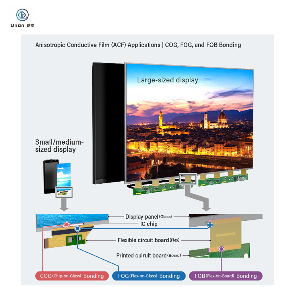
Anisotropic Conductive Film (ACF) serves as an adhesive for securing and electrically connecting electronic components, like integrated circuits (ICs), to circuit boards.
Originally introduced in 1977, ACF is now a staple in nearly all digital devices that employ flat panel displays—think smartphones, tablets, and high-definition TVs.
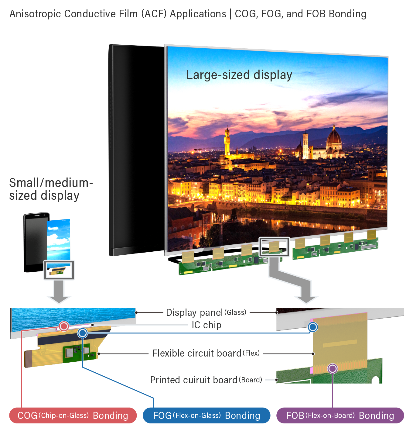
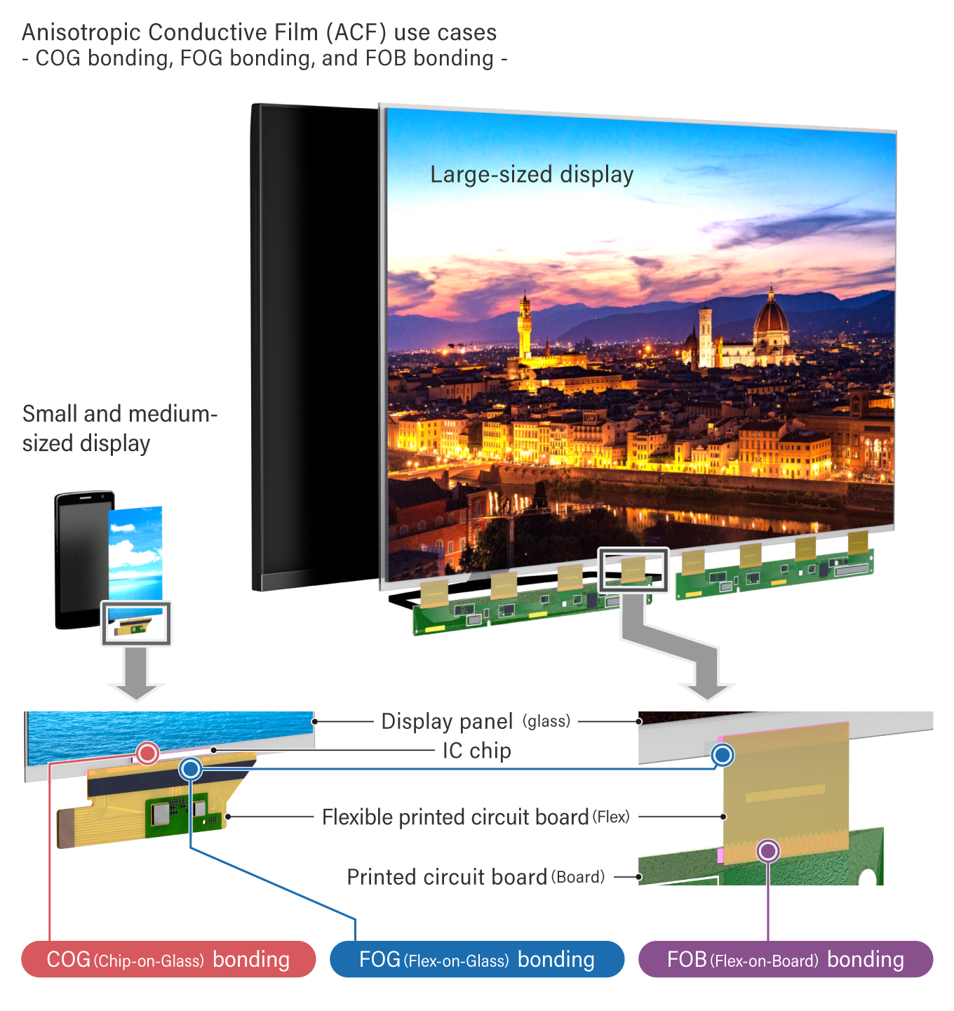
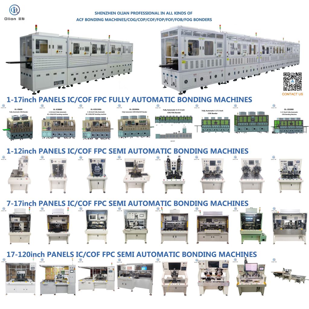
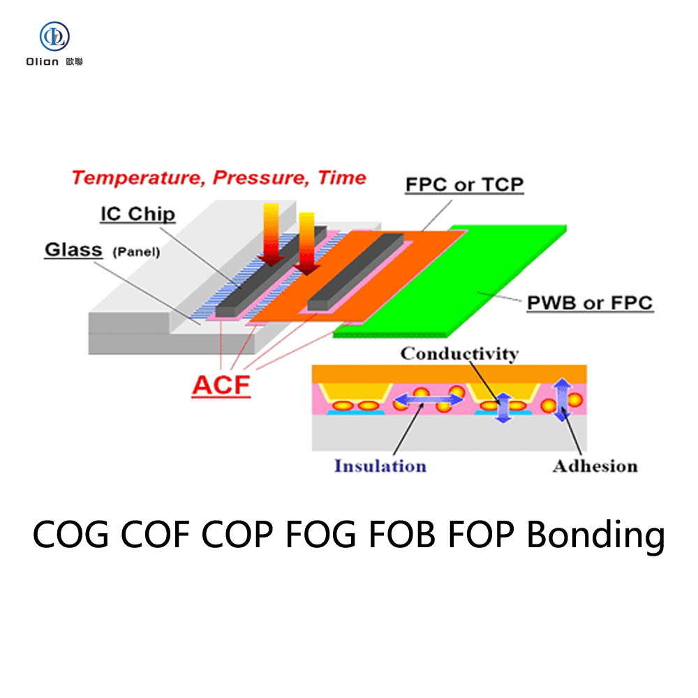
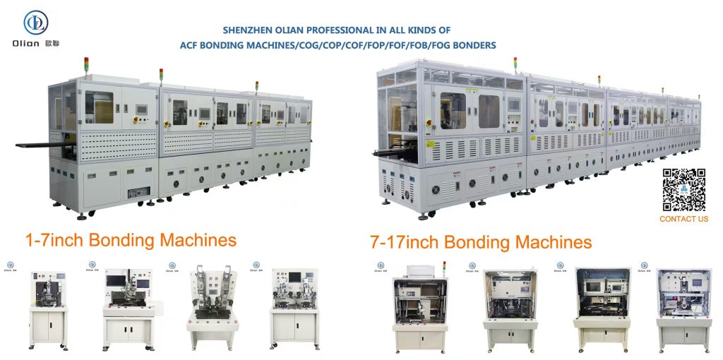
ACFs are typically used to connect the display panel to the flexible substrate that transmits signals to the panel or to the IC. Common applications of ACF include: COG (Chip-on-Glass), which connects the IC and glass substrate FOG (Flex-on-Glass), which connects the flexible substrate and glass substrate FOB (Flex-on-Board), which connects the flexible substrate and rigid substrate Other applications of ACF extend to smart cards, camera modules for CCDs (charge-coupled devices), and CMOSs (complementary metal oxide semiconductors). Shenzhen olian design and manufactur all the COG,COF,COP,FOG,FOB,FOP,FOF,TFOG,TFOF ACF bonding machines.
How ACFs can bond, conduct, and insulate
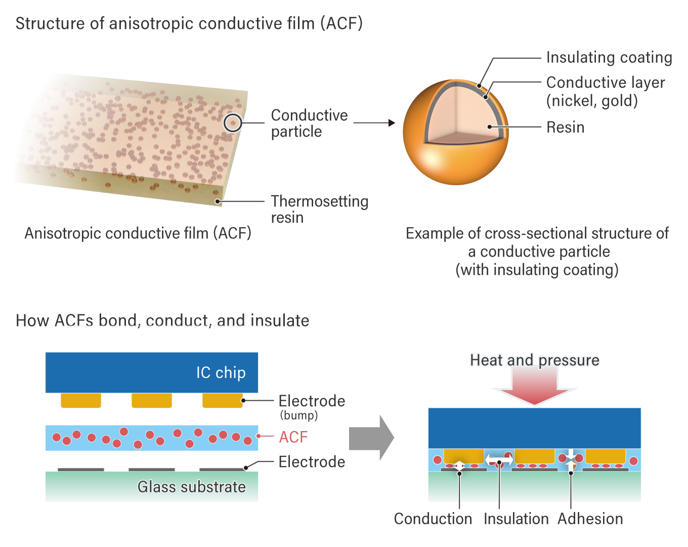
Anisotropic Conductive Film serves three primary functions simultaneously: adhesion, electrical conduction, and insulation. This unique capability allows manufacturers to connect a large number of pads at once.
Unlike traditional soldering, ACF enables fine pitch connections. The film is composed of conductive particles dispersed in a thermoset resin. A typical particle features a polymer core coated with nickel or gold, covered by an insulating layer.
When heat and pressure are applied, the opposing pads capture these particles. This process breaks the insulating coating to establish a vertical electrical connection. Particles trapped between pads remain insulated, preventing short circuits.
Key Technical Specifications:
Bonding Temperature: Ranges from 110°C to 180°C.
Film Thickness: Available from 10 to 45μm.
Film Width: Ranges from 0.5 to 20mm.
Roll Length: Available from 10 to 300m.
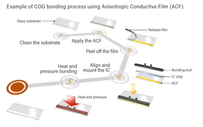
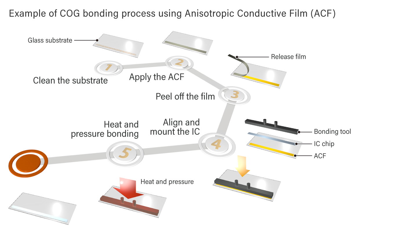
The ACF structure and bonding process
The bonding process is precise and efficient. Shenzhen Olian recommends following these steps for optimal results:
Clean the surface of the board to be attached.
Apply heat and pressure to the ACF with the release liner attached.
Peel off the release film carefully.
Align the pads of the IC chip to the ACF.
Apply heat and pressure again to finalize the bond.
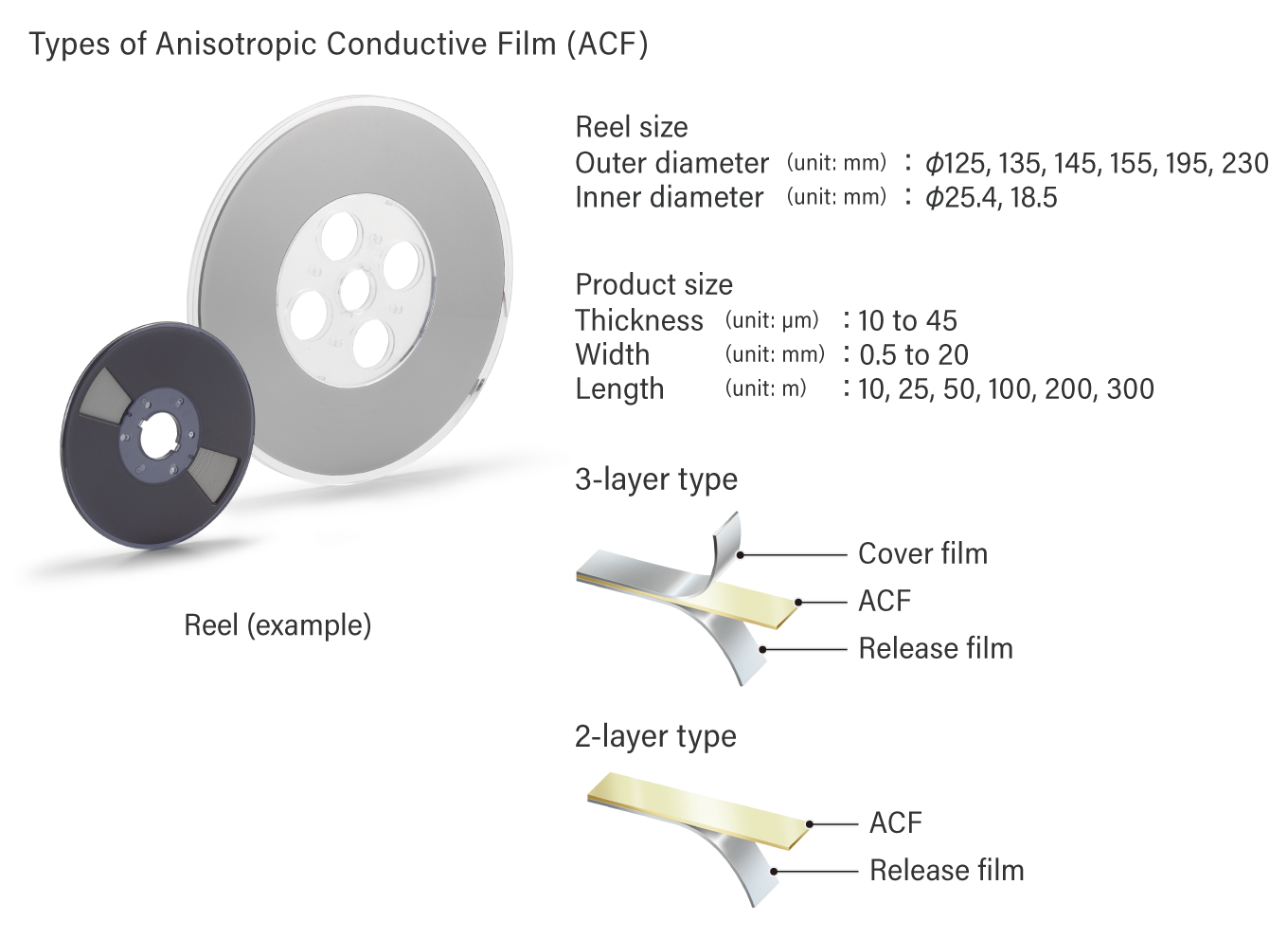
ACFs are sold in reels, as shown in the photo below. They come in a wide range of film thicknesses. From 10 to 45μm, widths from 0.5 to 20mm, and lengths from 10 to 300m.
The figure below illustrates two types of ACFs: a three-layer type, where ACF is sandwiched between a protective film and a release film.
And a two-layer type where only the release film is used. Each type offers different benefits. The three-layer type reduces the risk of dust contamination, while the two-layer type eliminates the need to remove the protective film during bonding.
The advantages of bonding components with ACFs
As technology advances each year, circuit boards are becoming increasingly fine pitch, the area of connecting pads is shrinking, and the spacing between them is narrowing.
While reflow soldering and connector components are traditionally used for bonding electronic components such as ICs to circuit boards, ACFs provide a solution to these trends.
However, a disadvantage of ACF is that it is challenging to bond components of different shapes simultaneously, which is common in reflow soldering.
Also, since ACF is an adhesive, it cannot be freely removed and reattached like mechanical connectors.
Why Choose ACF?
Benefits of ACF
Can bond components on glass substrates
Enables batch connections of multiple pads
Enables fine pitch connections
Pb-free
Quick bonding at relatively low temperatures
Thinner bonding area
The history of ACF and its innovation
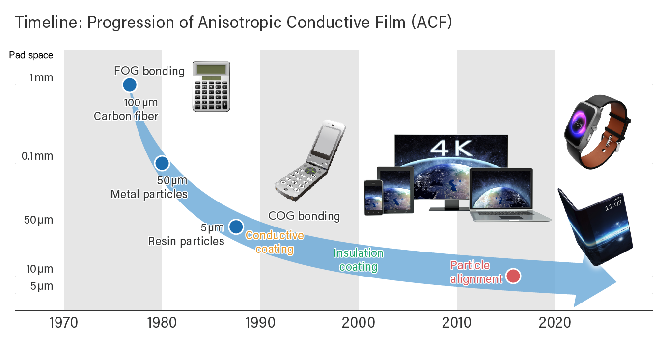
Dexerials has been continually enhancing ACF since its introduction in 1977. Initially, the conductive particles used were carbon fiber and solder particles. However, in 1988, Dexerials developed particles plated with nickel and gold.
By the 1990s, Dexerials had successfully developed a technology to coat the surface with insulating material.
As digital devices have evolved towards higher definition, Dexerials has adapted to the trend of fine pitch connections by reducing the particle size from 5μm to 2.8μm.
In 2014, Dexerials developed a technology to uniformly align conductive particles in thermosetting resin.
And in 2016, began marketing the product as “particle-arrayed Anisotropic Conductive Film” (ArrayFIX). This product contributes to the miniaturization, slimming design of digital devices, and higher resolution displays.
Selecting the best type of ACF
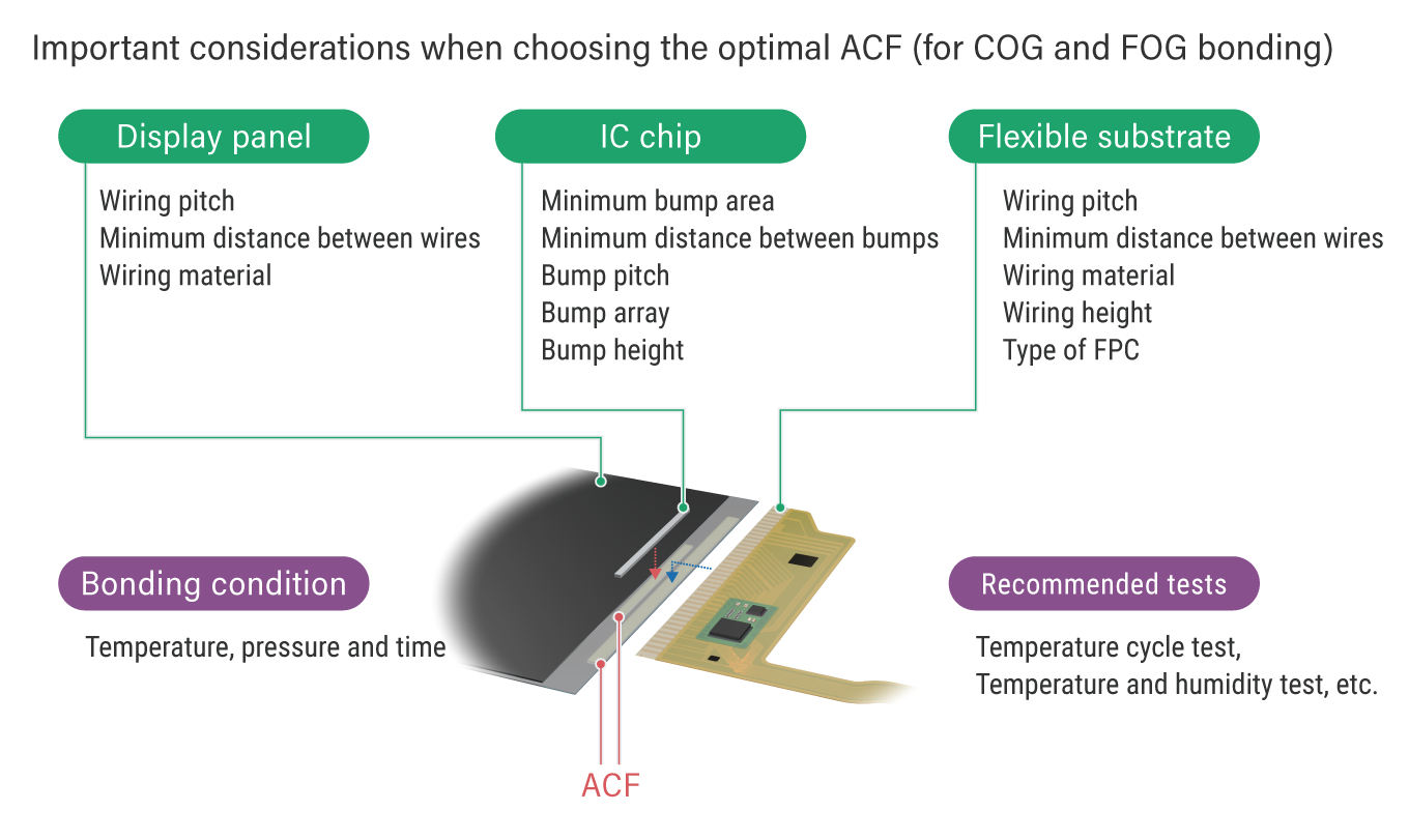
When selecting the best ACF, several factors should be considered, including the type of adherend, connection area, distance between pads, height of pads, and heat resistance.
ACF is composed of either epoxy resin or acrylic resin that cures with heat. we recommends acrylic ACF for applications where Flexible Printed Circuits (FPCs) and substrates (PCBs or glass substrates) are to be bonded, and where the design is intended to be reworked after the main bonding. (Please note that Dexerials does not recommend reworking itself. Dexerials advises that rework should only be done after reliability evaluations have been conducted to ensure that there are no issues.) Dexerials does not recommend ACF with epoxy resin if there is a possibility that the customer will rework. The primary reason is that it often damages the substrate to be reworked. This is because cured epoxy resin does not dissolve in solvents, and the process involves scraping off the residue.
Reworking after bonding typically involves heating the bonding area with a heat gun, hot iron, hot plate, etc., and then peeling off the FPC. Afterward, the cured resin residue between the pads on the board should be carefully removed using a solvent such as Methyl Ethyl Ketone (MEK) or N-Methyl-2-pyrrolidone (NMP) and a cotton swab. However, Dexerials does not recommend reusing FPCs because FPCs often curl during the peeling process and cleaning the resin residue between the pads on the FPC side is challenging.
With over 40 years of leadership in ACF technology, Dexerials can provide services including the initial setup, proposing an appropriate ACF, and post-connection analysis and evaluation. If you have any questions about ACF application, please feel free to contact us.
About Shenzhen Olian
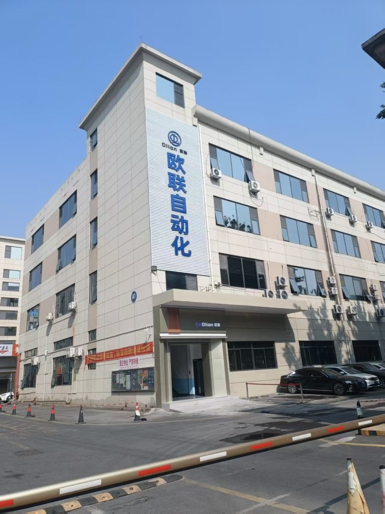
Shenzhen Olian Automatic Equipment Co., Ltd ,established in 2012, is a national high-tech enterprise specializing in the research and development, sales, production, and service of automation equipment for FPD flat panel displays and new flexible screen displays. The company holds multiple invention patents, utility model patents, and software copyrights. At present, the company has a professional R&D team of more than 100 workers, as well as a professional team for production management, quality management, and after-sales service.
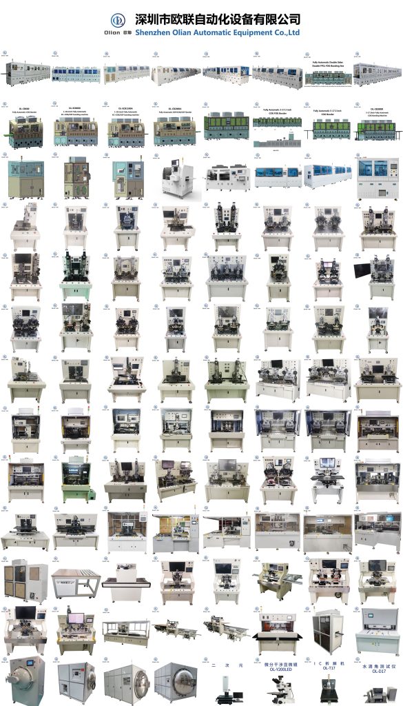
Olian’s products include LCM module factories and full process equipment (COG COF COP ,FOG FOB FOF FOP FOC TFOG TFOF bonding, AOI, dispensing, backlighting, soldering), achieving manufacturing of integrated display and touch products. The company’s series of products are widely used in display fields such as mobile phones, electronic tags, tablets, smart wearables, automotive displays, televisions, computers, etc., and provide overall solutions for smart factories.
ACF Bonding Machine Manufacturer for LCD Display Production
Discover how ACF bonding machines drive LCD/OLED/MINI LED/Microled/COP… display production — from COG/COF/COP/FOG/FOB/FOP/FOF/OLB bonding processes to choosing the right manufacturer. Explore bonding-machine.com for industry-leading solutions, technical specifications, and expert guidance on anisotropic conductive film bonding equipment.
ACF Bonding Machine Manufacturer for LCD Display Production: The Complete Guide to Choosing the Right Equipment
📌 Quick Navigation
What Is ACF Bonding and Why Does It Matter?
The Critical Role of ACF Bonding Machines in LCD Display Production
Types of ACF Bonding Processes: COG, COF, FOG Explained
Key Technical Specifications to Evaluate
How to Choose the Right ACF Bonding Machine Manufacturer
bonding-machine.com: Your Trusted ACF Bonding Equipment Partner
Industry Trends & Future Outlook
Frequently Asked Questions (FAQ)
What Is ACF Bonding and Why Does It Matter?
In the world of LCD and OLED display manufacturing, there’s a microscopic process that makes every screen you use possible — ACF bonding.
ACF stands for Anisotropic Conductive Film — a specialized adhesive material that conducts electricity vertically (through its thickness) while remaining electrically insulating horizontally (across its surface). Originally developed by Sony Chemical (now Dexerials) in 1977, ACF has become the indispensable “neural synapse” of modern display panels, enabling electrical connections between driver ICs, flexible printed circuits (FPCs), and glass substrates at pitches as fine as 30 micrometers or below.
Think of it this way: within an area roughly the size of a fingernail, hundreds of electrical contacts must be simultaneously connected with micron-level precision — that’s exactly what ACF bonding achieves. Without this technology, the smartphones, tablets, laptops, televisions, automotive displays, and industrial HMI screens we rely on every day simply couldn’t exist.
And the machine that makes this process happen? That’s the ACF bonding machine — the precision equipment that applies temperature, pressure, and alignment control to create reliable, repeatable electrical interconnections using ACF material.
The Critical Role of ACF Bonding Machines in LCD Display Production
LCD display production is a multi-stage manufacturing process where the bonding stage is arguably the most precision-demanding step. Here’s where ACF bonding machines fit in the production flow:
LCD Module Assembly Process Flow
Stage
Process
Equipment Category
1
Glass substrate cleaning
Cleaning equipment
2
ACF film lamination (attach ACF to glass)
ACF bonding machine (lamination unit)
3
Driver IC bonding (COG — Chip on Glass)
ACF bonding machine (COG bonder)
4
FPC bonding (FOG — Film/FPC on Glass)
ACF bonding machine (FOG bonder)
5
Protective sealing (silicone dispensing)
Dispensing equipment
6
Light-shielding tape application
Tape attaching equipment
7
Backlight unit (BLU) assembly
BLU assembly equipment
8
Final inspection & testing
Inspection equipment
As the table shows, ACF bonding machines are involved in at least 2–3 critical stages of LCD module assembly. The quality of bonding directly determines:
✅ Display image stability — no flickering, line defects, or dead pixels
✅ Signal transmission reliability — consistent electrical conductivity at every contact point
✅ Product lifespan — resistance to thermal cycling, mechanical stress, and environmental aging
✅ Yield rate — reducing rework and scrap directly improves production economics
A single bonding defect — a misaligned IC, insufficient ACF compression, or a trapped particle short — can render an entire display panel defective. This makes the choice of ACF bonding machine manufacturer a strategic production decision, not merely a procurement task.
Types of ACF Bonding Processes: COG, COF, FOG Explained
Understanding the different bonding configurations is essential when selecting equipment. Here’s a detailed breakdown:
1. COG (Chip on Glass) Bonding
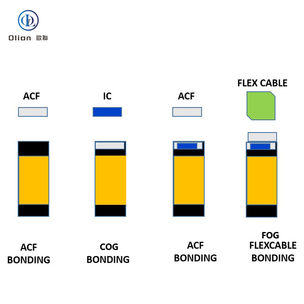
COG bonding attaches a bare driver IC chip directly onto the ITO (Indium Tin Oxide) electrode pads on the LCD glass substrate using ACF as the interconnect medium.
Process Steps:
ACF film is laminated onto the glass bonding area
The driver IC is aligned to the glass electrode pads using a high-precision vision alignment system
Pre-bonding (temporary attach) with low pressure
Main bonding with controlled temperature (typically 180–220°C), pressure (typically 15–30 MPa), and time (typically 8–15 seconds)
ACF resin thermosets, conductive particles are compressed to form vertical electrical pathways
Key Challenges:
Pin pitch down to 30 μm or finer requires sub-micron alignment accuracy
Uneven pressure distribution causes connection reliability issues
Thermal management must prevent glass substrate stress
2. COF (Chip on Film/FPC) Bonding
COF bonding mounts the driver IC onto a flexible printed circuit (FPC) film first, then the COF package is bonded to the glass substrate. This configuration is increasingly preferred for:
High-resolution displays with narrow bezels
Foldable/flexible OLED displays
Displays requiring bendable interconnects
Advantages over COG:
The IC can be bent around the display edge → narrower bezel
Better thermal dissipation through the FPC substrate
Easier repair — the entire COF module can be replaced
3. FOG (FPC on Glass) Bonding
FOG bonding connects the flexible printed circuit board (FPC) to the glass substrate terminal area. This is the signal bridge between the display panel and the external system (motherboard, T-CON board, etc.).
Process Flow (after COG is completed):
Glass terminal area is cleaned
ACF is laminated onto the glass bonding pads
FPC is aligned to the glass pads
Pre-bond → Main bond (thermocompression)
FOG is often the final electrical interconnection step before the LCD module enters final assembly and testing.
Comparison Table: COG vs COF vs FOG
Parameter
COG
COF
FOG
Bonded Component
Bare IC chip
IC-on-FPC package
FPC alone
Bonded To
Glass substrate
Glass substrate
Glass substrate
Bezel Impact
Wider (IC on surface)
Narrower (IC bends around edge)
Minimal (FPC at edge)
Pin Pitch
Finest (down to ~30 μm)
Fine (~40–60 μm)
Moderate (~80–150 μm)
Alignment Accuracy Required
±2–5 μm
±2–5 μm
±15–30 μm
Typical Applications
Standard LCDs, TN/STN
High-res LCD, OLED, foldable
All LCD/OLED modules
Repairability
Difficult (direct on glass)
Moderate (replace COF module)
Moderate
Equipment Needed
COG bonding machine
COF bonding machine
FOG bonding machine
Key Technical Specifications to Evaluate
When comparing ACF bonding machines from different manufacturers, these are the non-negotiable specifications that determine production capability:
🔧 Alignment Accuracy
Grade
Alignment Accuracy
Suitable For
Standard
±15 μm
FOG bonding, moderate-pitch applications
High-Precision
±5 μm
COF bonding, fine-pitch LCD/OLED
Ultra-High-Precision
±2 μm or better
COG bonding, finest pitch ICs
Tip from bonding-machine.com: Always verify alignment accuracy under actual production conditions (not just laboratory specs). Request a live demonstration with your specific product dimensions.
🌡️ Temperature Control
Temperature range: Typically 100–280°C
Temperature uniformity across bonding head: ±2°C or better
Ramp-up speed: Fast heating reduces process time and ACF pre-curing risk
Temperature measurement: Thermocouple embedded in bonding tool vs. infrared sensing
Precision temperature control is critical because ACF’s conductive particles must be compressed at the exact thermosetting temperature — too hot causes ACF degradation, too cold means incomplete curing and unreliable connections.
💪 Pressure Control
Pressure range: 2–5 MPa (adjustable for different ACF types and substrates)
Pressure uniformity: ±5% or better across bonding area
Parallelism of bonding head: Critical for uniform particle compression
Force measurement: Load cell-based real-time monitoring preferred
⏱️ Process Time & throughput
Single bond cycle time: 6–20 seconds (main bond)
UPH (Units Per Hour): Ranges from 300 to 1,200+ depending on machine configuration
Pre-bond + Main-bond sequential time: Total cycle including alignment, pre-bond, main-bond, and cooling
👁️ Vision Alignment System
The vision system is the “eyes” of the bonding machine. Key parameters:
Camera resolution: Minimum 2 megapixels; 5+ MP for ultra-fine pitch
Magnification: Adjustable (typically 2x–10x)
Alignment mark recognition: Support for multiple mark types (cross, circle, L-shape, custom)
💡 A machine that costs 20% more but delivers 3% higher yield can save hundreds of thousands of dollars annually on a high-volume production line.
Shenzhen Olian(bonding-machine.com): Your Trusted ACF Bonding Equipment Partner
At Shenzhen olian (bonding-machine.com), we understand that ACF bonding isn’t just a mechanical process — it’s the heart of display manufacturing. Our commitment goes beyond selling machines; we deliver complete bonding solutions.
What Sets bonding-machine.com Apart
🎯 Comprehensive Product Line
We offer ACF bonding machines covering the full spectrum of display production needs:
±15 μm alignment, high throughput, multi-FPC bonding capability
ACF-L Series
ACF Lamination
Pre-bond ACF attachment, high accuracy film positioning
Multi Series
Multi-function
COG+FOG or COF+FOG combined, flexible production line configuration
🔬 Deep Process Expertise
We don’t just deliver hardware. Our team of process engineers provides:
ACF bonding recipe development — optimized temperature/pressure/time parameters for specific ACF materials (Dexerials, Resonac, Hitachi Chemicals, and Chinese domestic ACF brands)
New product introduction (NPI) support — from first article bonding through production qualification
Yield improvement consulting — systematic defect analysis and process optimization
🌍 Global Service Network
Fast response: 24/7 remote technical support
On-site service: Engineers available for installation, training, and troubleshooting
Regional offices: Service hubs in key display manufacturing regions
Spare parts: Local inventory for critical components
🏭 Proven Track Record
Our machines are running in production lines at display manufacturers serving:
Smartphone and tablet LCD/OLED panels
Automotive infotainment and instrument cluster displays
Industrial HMI and medical display modules
Television and large-format display panels
Wearable and IoT device displays
Industry Trends & Future Outlook
The ACF bonding equipment industry is evolving rapidly alongside display technology advances. Here are the key trends shaping the future:
1. Finer Pitch, Higher Precision
As display resolutions increase (4K, 8K, and beyond), driver IC pin pitches continue shrinking. The industry is moving from 40 μm pitch toward 20 μm and below, requiring bonding machines with:
Alignment accuracy of ±2 μm or better
Higher-resolution vision systems (8+ MP cameras)
More sophisticated alignment algorithms with AI-assisted pattern recognition
2. Foldable & Flexible Display Bonding
Foldable OLED displays (used in smartphones and emerging foldable laptops) demand:
COF bonding as the primary configuration
Bonding machines capable of handling ultra-thin flexible substrates
Specialized ACF materials with enhanced bend reliability
New process parameters for flexible substrate bonding (lower temperature to protect flexible materials)
3. Mini LED & Micro LED Backlight Bonding
Mini LED and Micro LED displays require mass transfer bonding — connecting thousands of tiny LED chips to the substrate. This creates demand for:
High-speed multi-head bonding machines
Gang bonding (simultaneous bonding of multiple chips)
Specialized ACF or alternative interconnect materials
4. Automation & Smart Manufacturing
Industry 4.0 integration in bonding equipment includes:
MES (Manufacturing Execution System) connectivity — real-time production data upload
SPC (Statistical Process Control) — automatic monitoring of bonding parameters
Predictive maintenance — AI-based analysis of machine health data
Digital twin — virtual machine models for process simulation and optimization
5. Domestic ACF Material Adoption
With China now the world’s largest LCD panel producer, domestic ACF material suppliers are rapidly gaining market share (domestic ACF adoption rate has risen to approximately 25%). Bonding machines must be compatible with:
Both Japanese premium ACF (Dexerials, Resonac) and Chinese domestic alternatives
Different ACF specifications (thickness, particle size, curing temperature)
Flexible recipe management for quick material changeover
Frequently Asked Questions (FAQ)
Q1: What is the difference between ACF bonding and soldering?
A: ACF bonding uses anisotropic conductive film adhesive to create electrical connections through thermocompression, while soldering uses molten metal alloy. ACF bonding offers several advantages for display production:
Lower processing temperature (180–220°C vs. 250+°C for soldering)
No flux residues that could contaminate the display
Simultaneous connection of hundreds of contacts in a single bonding cycle
Suitable for glass substrates that cannot tolerate soldering temperatures
Compatible with fine-pitch connections below 40 μm
Q2: How long does an ACF bonding machine typically last?
A: With proper maintenance, a quality ACF bonding machine has a service life of 8–10 years or more. Key longevity factors include:
Regular calibration (typically monthly)
Bonding head replacement schedule (every 6–12 months depending on usage)
Servo system maintenance
Software updates and alignment system recalibration
Q3: Can one machine handle both COG and FOG bonding?
A: Yes. Multi-function bonding machines(full automatic bonding line) can handle both COG and FOG bonding in a single platform, typically through:
Changeable bonding head tooling
Switchable vision system configurations
Adjustable pressure and temperature ranges
This is ideal for factories producing multiple product types with moderate throughput needs.
Q4: What ACF materials are compatible with bonding machines?
A: Modern ACF bonding machines from reputable manufacturers are designed to work with the full range of commercially available ACF films, including:
Dexerials (formerly Sony Chemical) — industry benchmark
Resonac (formerly Hitachi Chemical) — widely used in automotive and industrial displays
Chinese domestic brands — rapidly improving quality, cost-effective alternative
Compatibility depends on ACF thickness (typically 15–40 μm), particle type (nickel, gold-coated, solder), and curing temperature profile. At bonding-machine.com, we test and certify compatibility with major ACF suppliers.
Q5: What is the typical yield rate for ACF bonding?
A: With a properly calibrated machine and optimized process, ACF bonding yield rates typically reach 98–99.5% for standard products. Factors affecting yield include:
ACF material quality and storage conditions
Glass substrate cleanliness
Alignment accuracy and consistency
Pressure and temperature uniformity
Operator skill and process discipline
Our process engineers at bonding-machine.com routinely help customers achieve and maintain >99% yield.
Q6: How do I get a quotation for an ACF bonding machine?
A: Simply contact our team with your production requirements — we’ll provide a detailed quotation including:
Machine configuration recommendation
Process capability assessment for your specific product
Delivery timeline and installation plan
Training and after-sales support package
TCO analysis comparison
Conclusion: The Right Manufacturer Is Your Production Partner
Choosing an ACF bonding machine manufacturer for LCD display production isn’t a transactional purchase — it’s a strategic partnership that directly impacts your product quality, production yield, and competitive position in the display market.
The ideal manufacturer provides not just a machine, but a complete bonding solution: equipment designed for your specific process needs, deep technical expertise in ACF bonding chemistry and physics, responsive after-sales support, and continuous innovation to keep pace with display technology evolution.
At bonding-machine.com, that’s exactly what we deliver — from our comprehensive bonding machine lineup to our process engineering support and global service network.
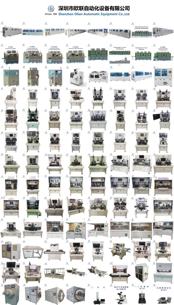
In the rapidly evolving world of electronics and display manufacturing, precision bonding technologies play a crucial role in creating high-quality, reliable, and innovative products. Whether you are producing smartphone screens, wearable devices, large TV panels, or advanced OLED displays, our company offers a comprehensive range of bonding machines and solutions to meet your specific needs. Below is an introduction to our product offerings, covering various bonding technologies and applications.
Chip on Glass (COG) Bonding Machines
COG (Chip on Glass) technology is a widely used method for mounting LCD driver chips directly onto the glass substrate of a display panel
. This technique is known for its simplicity, cost-effectiveness, and reliability. Our COG bonding machines are designed to provide high precision and efficiency, making them ideal for applications such as smartphone screens, LCD panels, and other display devices
. We offer both pre-bonding and main-bonding machines, ensuring accurate alignment and strong connections.
Chip on Film (COF) Bonding Machines
COF (Chip on Film) technology represents a significant advancement in display manufacturing. It involves mounting integrated circuits (ICs) onto flexible printed circuits (FPCs), which can then be bent and folded to fit compact spaces
. Our COF bonding machines support high-speed production and offer precise temperature and pressure control, ensuring reliable connections for applications such as flexible screens, smartwatches, and other wearable devices
. We provide both COF pre-bonding and main-bonding machines, tailored to meet the demands of modern display manufacturing
.
Chip on Plastic (COP) Bonding Machines
COP (Chip on Plastic) technology is another innovative approach, where ICs are mounted directly onto plastic substrates. This method is particularly useful for creating lightweight and flexible displays
. Our COP bonding machines are designed to handle the unique challenges of plastic substrates, offering high precision and reliability. These machines are ideal for applications such as flexible OLED displays and wearable devices
.
FPC on Glass (FOG) Bonding Machines
FOG (FPC on Glass) bonding involves attaching flexible printed circuits to glass substrates. This technique is commonly used in applications requiring flexibility and compact design, such as touch screens and wearable devices
. Our FOG bonding machines feature advanced alignment systems and precise temperature control, ensuring high-quality connections. We offer both hot press and automated bonding solutions for FOG applications
.
FPC on PCB (FOB) Bonding Machines
FOB (FPC on PCB) bonding machines are designed for attaching flexible printed circuits to printed circuit boards. These machines are essential for creating compact and reliable electronic assemblies, commonly used in smartphones, tablets, and other consumer electronics
. Our FOB bonding machines provide high precision and flexibility, supporting both manual and automated production processes
.
FPC on FPC (FOF) Bonding Machines
FOF (FPC on FPC) bonding involves connecting flexible printed circuits to each other. This technique is ideal for applications requiring extreme flexibility and compactness, such as wearable devices and flexible displays
. Our FOF bonding machines offer high precision and reliability, ensuring strong and durable connections.
Anisotropic Conductive Film (ACF) Bonding Machines
ACF (Anisotropic Conductive Film) bonding is a versatile technique used in various bonding processes, including COG, COF, and FOG
. Our ACF bonding machines are designed to provide precise temperature, pressure, and alignment control, ensuring reliable and high-quality connections. We offer a range of ACF bonding solutions, including pre-bonding and main-bonding machines
.
Tape Automated Bonding (TAB) Machines
TAB (Tape Automated Bonding) is a technique used for bonding integrated circuits to substrates using tape carriers. Our TAB bonding machines are designed for high-speed production and offer precise alignment and bonding capabilities
. These machines are ideal for applications requiring high-density interconnections and compact designs
.
Flexible Printed Circuit (FPC) Bonding Machines
FPC (Flexible Printed Circuit) bonding machines are essential for creating flexible and lightweight electronic assemblies. Our FPC bonding machines offer high precision and reliability, supporting various bonding processes and applications
. These machines are ideal for applications such as wearable devices, flexible displays, and other consumer electronics
.
Additional Bonding Solutions
In addition to the above technologies, we also offer specialized bonding machines for various applications, including:
Touch Panel FPC Bonding Machines: For bonding flexible circuits to touch panels.
Zebra Paper Bonding Machines: For bonding components to Zebra paper.
Pulse Hot Press Machines: For applications requiring rapid heating and cooling.
OLED Bonding Machines: For bonding OLED displays.
Camera FPC Bonding Machines: For bonding flexible circuits to camera modules.
Why Choose Our Bonding Machines?
Our bonding machines are designed with the latest innovations in mind, ensuring high precision, reliability, and efficiency. Key features of our machines include:
High Precision: Equipped with advanced vision systems and precise temperature control.
Versatility: Support a wide range of bonding processes and applications.
Automation: Available in both semi-automatic and fully automatic configurations.
Customization: Tailored solutions to fit your specific manufacturing processes and requirements.
Conclusion
Whether you are producing smartphone screens, wearable devices, large TV panels, or advanced OLED displays, our comprehensive range of bonding machines is designed to meet your specific needs. With advanced features such as high precision, versatility, and automation, our machines are ideal for ensuring high-quality connections and efficient production processes. Contact us today to find the perfect bonding machine for your application.