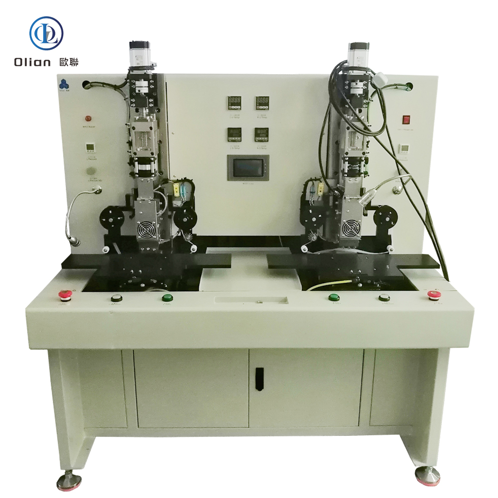
OL-C0156 – 15.6-Inch Dual-Station IC Servo Main Bonding Machine
OL-C0156 – 15.6-Inch Dual-Station IC Servo Main Bonding Machine
High-Efficiency Thermal Compression System for Continuous COG Production
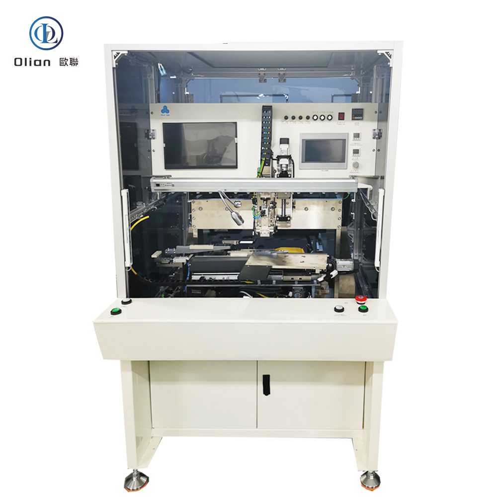
The OL-C0156 by Olian Automatic Equipment Co., Ltd. is a semi-automatic dual-station main bonding machine designed for the final thermal compression of bare driver IC chips onto ACF-pre-laminated edge terminals of large-format rigid LCD panels up to 15.6 inches. Featuring two independent workstations, this system enables continuous operation: while one station is bonding, the operator can load/unload the other—dramatically improving workflow efficiency and reducing idle time.
As a dedicated COG (Chip-on-Glass) main bonder, the OL-C0156 fully cures the anisotropic conductive film (ACF) under precise heat and servo-controlled pressure, ensuring robust electrical connections and long-term display reliability in demanding applications such as automotive dashboards, industrial HMIs, and medical monitors.
⚠️ Note: This machine assumes that ACF has already been applied and the IC has been pre-aligned (e.g., via a pre-bonder). It performs single-zone, single-side bonding only and does not include vision alignment or double-side capability.
🔧 Key Technical Specifications
Substrate & Component Compatibility
Panel Size:
Max: 350 mm × 250 mm (~15.6″ diagonal)
Min: 150 mm × 80 mm (~7″)
Thickness: 0.2 – 2.2 mm
IC Dimensions:
Length: 5 – 40 mm
Width: 0.5 – 3 mm
Thickness: 0.08 – 0.5 mm
Bonding Configuration:
Single-side, single-segment per cycle
Dual independent stations for alternating operation
Bonding Performance
Heating System:
Cartridge-style heating rods (exact size not specified; standard Olian design)
Temperature Range: Room temperature to 400°C
Surface Uniformity: ≤ ±3°C across press head
Pressure Control:
Servo motor-driven actuator for ultra-stable force
HMI: Color touchscreen by Weinview / HMI brand (显控)
Operating Modes:
Manual Mode: Full control over head movement
Auto Mode: One-button cycle after panel placement
Physical Controls:
Start Button (Φ24 mm)
Vacuum Button (Φ24 mm)
Emergency Stop (Φ22 mm, red mushroom type)
Main Power Switch
Process Workflow
Operator loads Panel A onto Station 1 and activates vacuum.
Starts bonding cycle on Station 1.
While bonding occurs, operator loads Panel B onto Station 2.
Upon completion at Station 1, operator unloads Panel A and starts bonding on Station 2.
Cycle repeats—enabling near-continuous production with minimal downtime.
This dual-station layout is ideal for lean manufacturing cells where operator efficiency and throughput are critical.
📏 Machine Physical Data
Dimensions: Approx. 1420 mm (W) × 1210 mm (D) × 1912 mm (H)
Weight: ~780 kg
Work Height: Platform at 890 ± 30 mm from floor—ergonomic for standing operation
Power Supply:
Single-phase AC 220V, 50/60 Hz
Power Consumption: 2000 W
Power cable exits bottom side, ~1.5 m length
Compressed Air:
Pressure: 0.4 – 0.7 MPa
Air Consumption: ~250 L/min
Tube: Transparent Φ8 mm with quick-connect fittings
Vacuum:
Controlled via vacuum button
Flow rate: ~36 L/min
Tube: Yellow color (connected to factory vacuum system)
🛡️ Quality Assurance & Support
Documentation: Includes 1 Chinese-language operation manual
Training: 1-day on-site session covering:
Machine setup and calibration
Dual-station workflow optimization
Parameter tuning for different IC types
Common fault diagnosis and maintenance
Warranty: 12 months on mechanical and electrical systems under normal use
Exclusions: Wear parts (buttons, seals), damage from misuse, or force majeure
After-Sales Service:
Lifetime technical support
On-site engineer within 72 hours if remote troubleshooting fails during warranty
✅ Included Standard Components
Custom IC bonding head (tooling per customer drawing)
Heating elements & thermocouples (K-type)
Φ24 mm start and vacuum buttons
Φ22 mm emergency stop switch
National-standard (GB) maintenance toolkit
🔖 Model Summary
Model: OL-C0156
Function: Dual-station, single-head IC main bonder for COG process
Panel Size: Up to 15.6 inches
Core Advantage: Continuous production flow via dual workstations
Target Industries: Automotive displays, industrial automation, medical electronics, consumer displays
🔎 SEO Keywords (for Global Visibility)
15.6 inch dual-station IC main bonding machine, OL-C0156 Olian, two-table COG热压机 for LCD, servo IC bonding equipment with dual workstations, single-zone IC本压机 for high-efficiency production, 400°C hot bar main bonder with Panasonic PLC, continuous COG bonding system for automotive displays, dual-platform IC热压设备, OL-C0156 technical datasheet, high-repeatability IC bonding machine with ±3N precision.
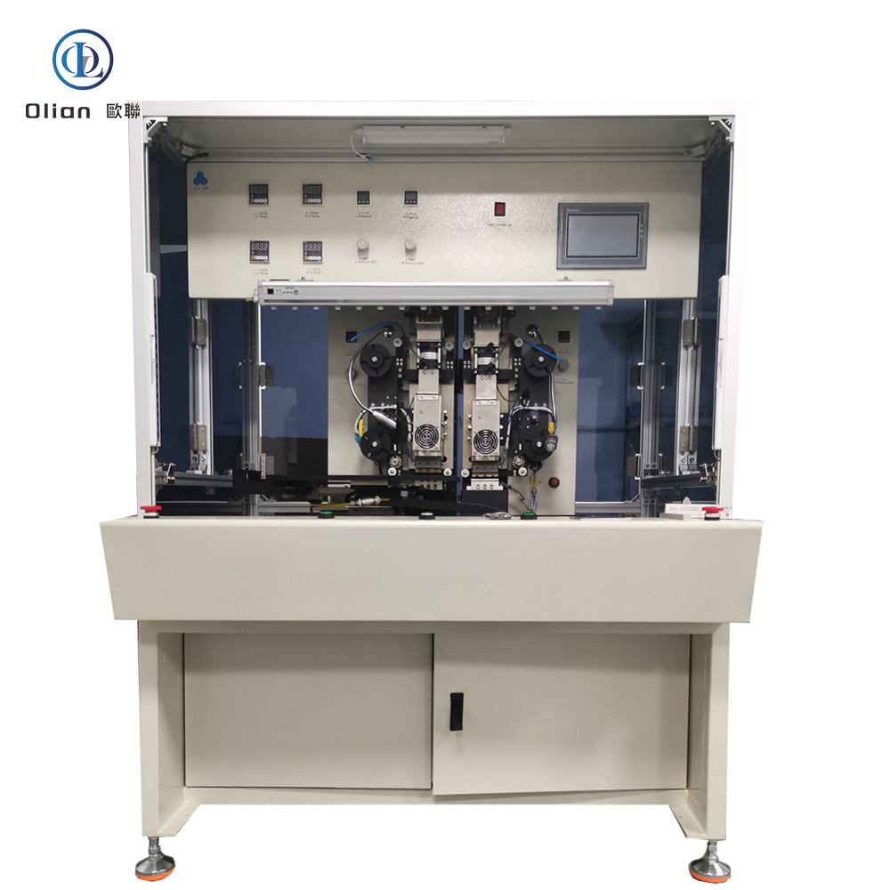
OL-CBY156 – 15.6-Inch Dual-Head IC Servo Main Bonding Machine
OL-CBY156 – 15.6-Inch Dual-Head IC Servo Main Bonding Machine
High-Efficiency Thermal Compression System for IC Bonding on 7-17.3inch LCD Panels
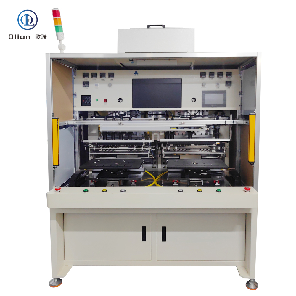
The OL-CBY156 by Olian Automatic Equipment Co., Ltd. is a semi-automatic dual-head main bonding machine engineered for the final thermal compression of bare driver IC chips onto ACF-pre-laminated edge terminals of large-format rigid LCD panels up to 15.6 inches. Featuring two independent servo-controlled bonding heads, this system enables either simultaneous bonding of two ICs or sequential multi-zone processing along a single panel edge—significantly boosting throughput while maintaining high bond consistency.
As the critical final step in the COG (Chip-on-Glass) process, the OL-CBY156 fully cures the anisotropic conductive film (ACF), creating permanent, low-resistance electrical interconnects essential for display reliability in automotive, industrial, and consumer applications.
⚠️ Note: This machine assumes that ACF has already been applied and ICs have been pre-aligned (e.g., via a pre-bonder). It does not include ACF application, vision alignment, or double-side bonding capability.
🔧 Key Technical Specifications
Substrate & Component Compatibility
Panel Size:
Max: 350 mm × 250 mm (~15.6″ diagonal)
Min: 150 mm × 80 mm (~7″)
Thickness: 0.2 – 2.2 mm
IC Dimensions:
Length: 5 – 40 mm
Width: 0.5 – 3 mm
Thickness: 0.08 – 0.5 mm
Bonding Configuration:
Single-side only
Supports up to 10 bonding segments per edge
Dual-head operation: Parallel or sequential bonding
Bonding Performance
Heating System:
Heater Type: Cartridge-style Φ9.5 mm × 70 mm heating rods (per head)
Temperature Range: Room temperature to 400°C
Surface Uniformity: ≤ ±3°C across each press head
Pressure Control:
Servo-driven actuators (independent for each head)
Adjustable Force: 20 N to 120 N
Repeatability: ≤ ±3 N
Bonding Time: 0.1 – 99.9 seconds (programmable per head)
Control & Operation
Control Unit:
PLC-based logic controller
Color touchscreen HMI (Chinese interface) for parameter setup and monitoring
Real-time display of temperature, time, pressure, and system status
Operating Modes:
Manual Mode: Full operator control over each head
Auto Mode: One-button cycle with coordinated dual-head action
Replacement of wear parts (heaters, thermocouples, buttons)
Warranty: 12 months on mechanical and electrical systems under normal use
Exclusions: Consumables, damage from misuse, or force majeure
After-Sales Service:
Lifetime technical support via phone/email
On-site engineer dispatch within 72 hours if remote resolution fails during warranty
✅ Included Standard Components
Two custom IC bonding heads (tooling per customer drawing)
Φ9.5 × 70 mm cartridge heaters (×2)
K-type thermocouples for closed-loop temperature control (×2)
Φ24 mm start and vacuum buttons
Φ22 mm emergency stop switch
National-standard (GB) maintenance toolkit
🔖 Model Summary
Model: OL-CBY156
Function: Single-station, dual-head IC main bonder for COG process
Panel Size: Up to 15.6 inches
Core Advantage: Higher throughput via dual servo heads with ±3 N repeatability
Target Applications:
Automotive center-stack displays
Industrial HMIs with redundant drivers
Medical monitors requiring dual ICs
High-mix display module production
🔎 SEO Keywords (for Global Visibility)
15.6 inch dual-head IC main bonding machine, OL-CBY156 Olian, double hot bar COG bonder for LCD, servo-controlled dual IC bonding machine, high-throughput IC bonding equipment for display panels, multi-zone dual-head bonding machine, 400°C dual press head main bonder, simultaneous IC bonding machine for automotive displays, dual servo IC main bonding machine with PLC control, OL-CBY156 technical specifications. COG Bonder, COP bonder, COF bonder, Main bonding machine, Final bonding machine, final main bonding machine,main bonder,Final bonder.
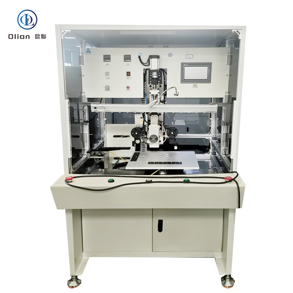
OL-CBD156 – 15.6-Inch Single-Station IC Servo Main Bonding Machine,
High-Precision Thermal Compression System for Final IC Bonding on LCD Panels
The OL-CBD156 by Olian Automatic Equipment Co., Ltd. is a semi-automatic main bonding machine designed for the final thermal compression of bare driver IC chips onto ACF-pre-laminated edge terminals of large-format rigid LCD panels up to 15.6 inches. As the critical last step in the COG (Chip-on-Glass) process, this system delivers consistent, high-reliability interconnects through precise servo-controlled pressure, uniform heating, and stable mechanical alignment—ensuring low contact resistance and long-term display performance.
Unlike pre-bonders or ACF applicators, the OL-CBD156 performs full-strength main bonding, fully curing the anisotropic conductive film to create permanent electrical and mechanical connections between the IC and glass substrate.
⚠️ Note: This machine assumes that ACF has already been applied and the IC has been pre-aligned (e.g., via a pre-bonder). It does not include ACF application, vision alignment, or double-side capability.
🔧 Key Technical Specifications
Substrate & Component Compatibility
Panel Size:
Max: 350 mm × 250 mm (~15.6″ diagonal)
Min: 150 mm × 80 mm (~7″)
Thickness: 0.2 – 2.2 mm
IC Dimensions:
Length: 5 – 40 mm
Width: 0.5 – 3 mm
Thickness: 0.08 – 0.5 mm
Bonding Zones: Supports up to 10 segments along a single edge (multi-zone sequential bonding)
Bonding Performance
Heating System:
Heater Type: Cartridge-style Φ9.5 mm × 70 mm heating rods
Temperature Range: Room temperature to 400°C
Surface Uniformity: ≤ ±3°C across press head
Pressure Control:
Servo-driven actuator for ultra-stable force output
Pre-placed IC (from pre-bond station) is positioned over the bonding zone.
Operator initiates cycle via start button.
Servo press head descends with precise force, applies heat for preset duration.
Upon completion, head retracts; operator unloads the fully bonded panel.
For multi-segment panels, the process repeats at each IC location.
💡 Smart Feature: The machine includes a “tape not feeding” alarm—if the carrier tape (e.g., from IC feeder) fails to advance, the system halts and alerts the operator to prevent missed bonds.
📏 Machine Physical Data
Dimensions: Approx. 1420 mm (W) × 1210 mm (D) × 1912 mm (H)
Weight: ~780 kg
Work Height: Platform at 890 ± 30 mm from floor—ergonomic for standing operation
Operating Environment:
Cleanroom required (ISO Class 8 or better)
Temperature: 22–27°C
Humidity: 40–70% RH
🛡️ Quality Assurance & Support
Documentation: Includes 1 Chinese-language operation manual
Training: 1-day on-site session covering:
Machine installation and calibration
Parameter optimization for different IC types
Troubleshooting common faults (e.g., poor adhesion, pressure deviation)
Replacement of wear parts (heaters, thermocouples, buttons)
Warranty: 12 months on mechanical and electrical systems under normal use
Exclusions: Consumables (seals, buttons), damage from misuse, or force majeure
After-Sales Service:
Lifetime technical support
On-site engineer within 72 hours if remote assistance fails during warranty
✅ Included Standard Components
Custom IC bonding head (tooling per customer drawing)
Φ9.5 × 70 mm cartridge heaters
K-type thermocouples for temperature feedback
Φ24 mm start and vacuum buttons
Φ22 mm emergency stop switch
National-standard (GB) maintenance toolkit
🔖 Model Summary
Model: OL-CBD156
Function: Single-station, single-head IC main bonder for COG process
IC Bonder,ACF IC bonder,IC bonding machine, COF bonding machine, COG bonding machine, IC final main bonding machine, IC main bonder,IC final bonder,COG ,COF,COP bonding machine, COP bonder, 15.6 inch IC main bonding machine, OL-CBD156 Olian, single-head COG bonder for LCD, servo-controlled thermal compression machine, multi-zone IC bonding equipment for display panels, high-precision IC main bonding machine with ±3N repeatability, 400°C hot bar main bonder for driver ICs, single-station COG bonding system, IC main bonding machine for automotive and industrial displays, servo IC final bonder with PLC and touchscreen.
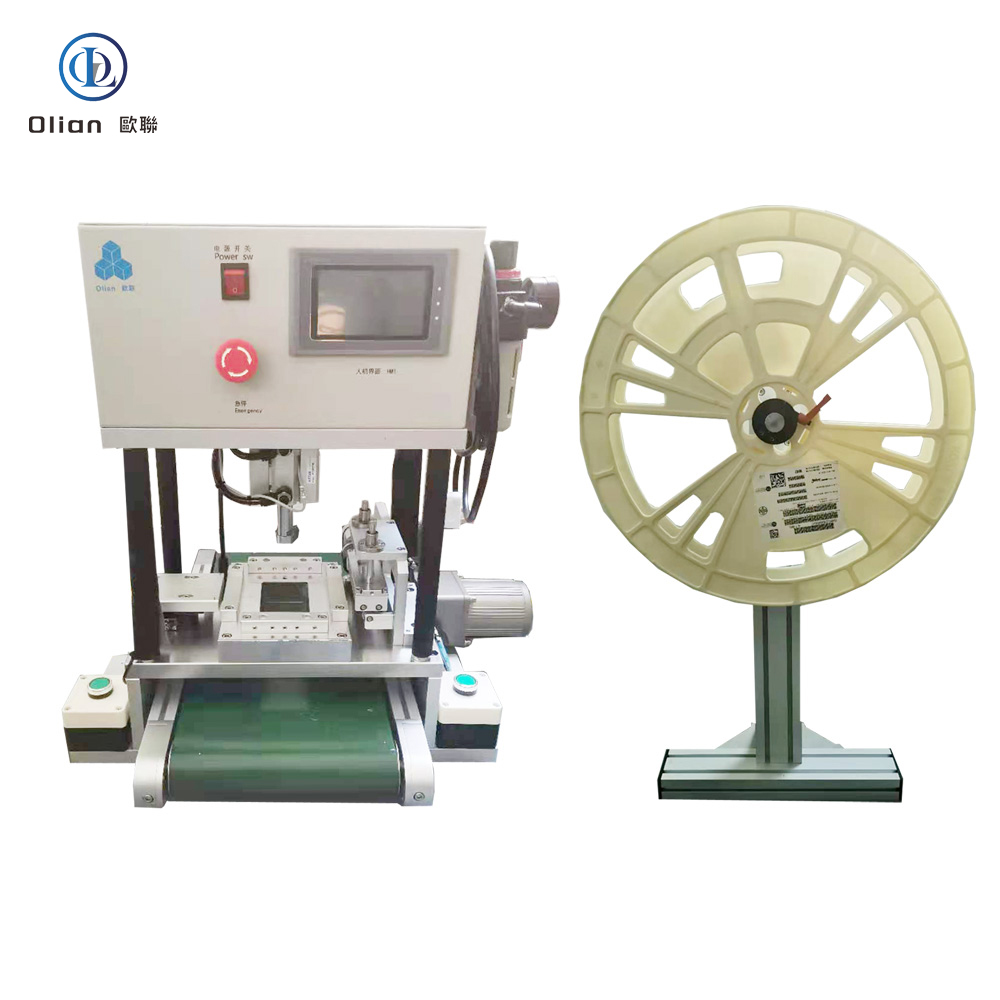
The OL-A156 by Olian Automatic Equipment Co., Ltd. is a semi-automatic ACF (Anisotropic Conductive Film) applicator engineered for high-accuracy lamination of ACF tape onto single-edge bonding zones of large-format rigid LCD panels up to 15.6 inches. Designed as the critical first step in COG/FOG (Chip-on-Glass / Film-on-Glass) display assembly processes, this machine ensures consistent ACF placement, tension control, and pre-compression—laying the foundation for reliable electrical interconnects in subsequent bonding stages.
Unlike manual taping or full-auto systems, the OL-A156 strikes an ideal balance between operator-guided flexibility and automated precision, making it perfect for medium-volume, high-mix production environments such as automotive displays, industrial HMIs, medical monitors, and premium consumer electronics.
⚠️ Note: This machine only applies ACF tape—it does not perform COF/IC bonding, vision alignment, or double-side processing.
🔧 Key Technical Specifications
Substrate Compatibility
Panel Size:
Max: 350 mm × 250 mm (diagonal ~15.6″)
Min: 150 mm × 80 mm (~7″)
Thickness: 0.2 – 2.2 mm
ACF Tape:
Width: 0.3 – 3.0 mm
Core Diameter: Φ19 mm or Φ25 mm
Max Roll Outer Diameter: ≤240 mm
ACF Application System
Feeding Mechanism:
Tension-controlled motorized unwind + fixed material reel
Ensures consistent tape tension during feeding and cutting
Cutting & Placement:
Precision pneumatic cutter with programmable length
Manual positioning of panel under ACF head (operator-assisted)
Pre-Compression:
Integrated press head applies controlled force to adhere ACF to glass
Back pressure plate made of SUS440C stainless steel for flatness and durability
Temperature & Control
Heating Capability:
Press head temperature: Room Temperature to 150°C
Surface uniformity: ≤ ±3°C
Control Unit:
PLC-based logic controller
Color touchscreen HMI (Chinese interface) for parameter setting
Real-time display of temperature, time, and system status
Operation Modes
Manual Mode: Full operator control over ACF feed, cut, and press
Auto Mode: One-button cycle after panel placement and alignment
Safety Interlocks: Dual-hand start option available (inferred from standard design)
Precision Thermal Alignment System for COF/IC to LCD Panel Assembly
The OL-COF156 by Olian Automatic Equipment Co., Ltd. is a semi-automatic pre-bonding machine engineered for the initial alignment and temporary bonding of Chip-on-Film (COF) or bare IC chips onto large-format rigid LCD panels up to 15.6 inches. Designed as the critical first step in the FOG (Film-on-Glass) or COG (Chip-on-Glass) process chain, this system ensures accurate terminal registration and secure tacking before final main bonding—dramatically reducing misalignment defects and rework rates.
Unlike full bonding machines, the OL-COF156 focuses exclusively on pre-compression: applying controlled heat and pressure to activate the ACF just enough to hold components in place during transfer to the main bonder.
🔍 Key Applications
Pre-bonding of COF tapes and driver ICs onto LCD/OLED display panels
Temporary fixation of touch sensor flex circuits
High-mix production of industrial, automotive, medical, and consumer displays
Ideal for panels requiring multi-segment or single-edge bonding
⚠️ Note: This machine performs pre-bonding only—it does not apply ACF, conduct final bonding, or support double-side processing.
🛠️ Core Technical Specifications
Substrate Compatibility
LCD Panel Size:
Max: 15.6 inches (350 mm × 250 mm)
Min: 7 inches (150 mm × 80 mm)
Thickness: 0.2 – 2.2 mm
COF Dimensions:
Length: 12 – 60 mm
Width: 12 – 30 mm
Thickness: 0.02 – 0.2 mm
Minimum mark pitch: ≥11 mm
IC Dimensions:
Max: 40 mm × 3 mm
Min: 5 mm × 0.5 mm
Thickness: 0.08 – 0.5 mm
Step Requirement: COF/IC must maintain a ≥0.4 mm height difference from the glass surface for proper head clearance
Bonding Performance
Heating System:
Heater Type: Cartridge-style Φ6 mm × 75 mm heating rods
Temperature Range: Room temperature to 400°C
Control Accuracy: ±2°C
Pressure & Time:
Adjustable bonding force via precision air regulator
15.6 inch COF pre-bonding machine, OL-COF156 Olian, single-side COF tacking system, LCD panel pre-bonder for COF and IC, semi-automatic FOG pre-compression machine, thermal alignment system for display driver chips, multi-zone COF pre-bond equipment, 400°C hot bar pre-bonder for LCD, COF temporary bonding machine with vacuum platform, display module pre-bond workstation for automotive and industrial panels.
High-Coverage Thermal Compression System for Rigid PCB + FPC Assembly
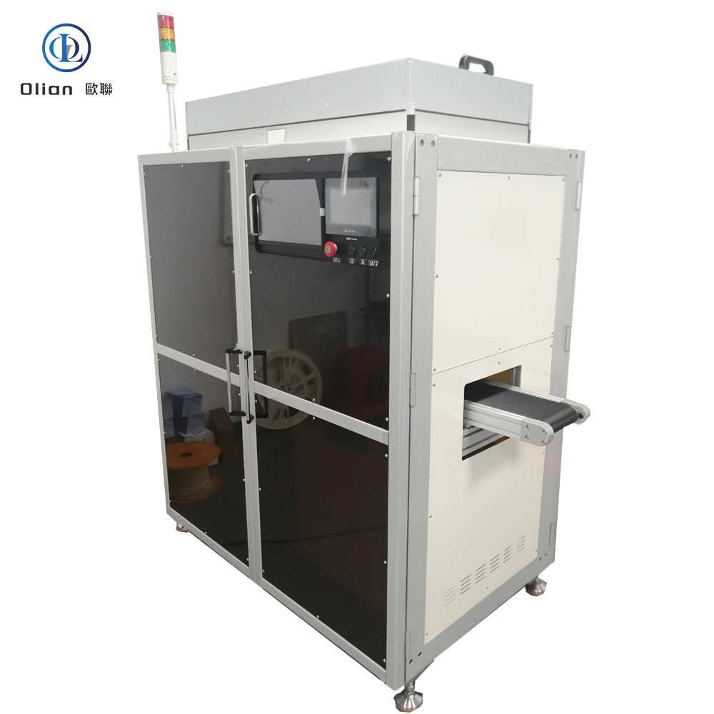
The OL-FFB-156L by Olian Automatic Equipment Co., Ltd. is a semi-automatic thermal compression bonding machine designed for single-side Flexible-on-Board (FOB) assembly of large-format rigid printed circuit boards (PCBs) up to 15.6 inches in diagonal size. It bonds flexible printed circuits (FPCs)—typically pre-laminated with anisotropic conductive film (ACF)—to PCB edge terminals using a long, high-uniformity press head capable of covering extended bond zones in a single stroke.
Unlike its short-head counterpart (OL-FFB-156S), this model is optimized for applications requiring simultaneous bonding across multiple terminal rows or long continuous FPC leads, reducing cycle time and improving process consistency for high-pin-count interfaces such as display driver boards, touch controller modules, or industrial I/O panels.
⚠️ Note: This machine performs thermal compression bonding only—it does not apply ACF, nor does it support chip-on-glass (COG) or optical auto-alignment.
Bonding Principle & Operational Workflow
The OL-FFB-156L follows a manual-load, semi-automatic press workflow tailored for operator-assisted precision:
PCB Loading: The operator places the bare rigid PCB onto the vacuum-equipped worktable.
PCB Fixturing: By pressing the vacuum button (Φ24 mm), the PCB is held flat and immobile during subsequent steps.
FPC Placement: The ACF-pre-laminated FPC—often supported by a temporary glass carrier for rigidity—is manually positioned over the PCB bonding area and roughly aligned.
FPC Fixturing: Vacuum is activated to gently secure the FPC/glass assembly in place.
Manual Visual Alignment: The operator observes the terminal overlap through an external monitor (implied imaging system) and fine-tunes the FPC position by hand to ensure proper registration.
Bond Initiation: The operator presses two start buttons simultaneously (dual-hand safety interlock). The platform then:
Automatically advances forward to the designated bonding position
The long press head descends vertically
Heat and pressure are applied for the preset duration
Upon completion, the head retracts automatically
Unloading: The bonded assembly is removed manually, and the cycle repeats.
This workflow balances operator control with automated pressing—ideal for medium-volume production requiring consistent bond quality.
Key Technical Specifications
Maximum Substrate Compatibility: Supports PCBs up to 15.6-inch diagonal (exact dimensions defined by worktable)
Press Head:
Standard length: 200 mm × 2.0 mm (long profile for wide or multi-row coverage)
Customization: Available per customer drawing for non-standard layouts
Temperature Control:
Press head range: Room temperature to 400°C
Surface uniformity: ≤ ±8°C across the entire 200 mm length
Back pressure plate: RT to 150°C, uniformity ≤ ±5°C (provides counter-support to prevent PCB warpage)
Bonding Time: Adjustable from 0.1 to 99.9 seconds
Bonding Force: 55 N to 1000 N, pneumatically regulated for repeatable contact pressure
Heating System:
Cartridge heaters: Φ9.5 mm × 45 mm embedded in the head
Temperature feedback: K-type thermocouples for closed-loop PID control
Control, Safety & ESD Protection
Operator Interface: Color touchscreen HMI for setting time, temperature, and monitoring status
Start Mechanism: Dual Φ24 mm push buttons requiring simultaneous press—ensures hands are clear during actuation
Emergency Stop: Φ22 mm mushroom-type EMO switch that cuts power to motion systems and enables manual platform override
Visual/Audible Alarms:
Three-color signal tower (green = ready, yellow = running, red = fault)
Buzzer for error alerts
ESD Safeguards:
All surfaces in contact with PCB/FPC use anti-static materials
Static voltage on panel surface maintained < ±100 V
Static decay performance: 1000 V → 100 V in ≤4 seconds
Grounding resistance: ≤5 Ω
Wrist strap sockets provided at material handling stations
These measures ensure compatibility with sensitive electronic assembly environments.
Mechanical Design & Utility Requirements
Frame: Heavy-duty steel construction with precision linear guides for smooth platform motion
Motion System: Servo-driven stage for accurate front-back positioning
Power Supply: Single-phase 220V AC, typical power draw ~2.5–3.5 kW (inferred from heater count and temp range)
Compressed Air: Required for press actuation and vacuum generation (0.5–0.7 MPa, clean and dry)
Applications
Ideal for bonding:
High-pin-count FPCs on large LCD/OLED display driver PCBs
Multi-row connector interfaces in automotive infotainment systems
Industrial control panels with extended flex tails
Medical imaging device backplanes requiring full-length terminal adhesion
Particularly advantageous when uniform pressure and temperature across a long bond line are critical to reliability.
Important Clarifications
Single-side bonding only: FPC is bonded to one edge of the PCB
Manual alignment: No auto-vision or motorized X/Y correction—alignment is operator-performed under monitor guidance
ACF must be pre-applied: Machine assumes ACF is already laminated on PCB or FPC
Designed for rigid PCBs, not glass substrates (unlike FOG machines)
Long press head: Enables single-stroke bonding of extended zones but requires sufficient clearance for the 200 mm head
Training, Warranty & After-Sales Support
Olian Automatic provides end-to-end support:
Documentation: One Chinese-language operation manual included
On-Site Training: One full day covering:
Machine installation and leveling
Parameter setup (temp/time/force calibration)
Routine maintenance and heater/thermocouple replacement
Troubleshooting common alarms and errors
Warranty: 12 months on mechanical and electrical components under normal operating conditions
Exclusions: Consumables (seals, buttons), damage from misuse, or force majeure events
Service Commitment:
Remote diagnostics via phone or email
On-site engineer dispatch within 72 hours if remote resolution fails during warranty period
Lifetime technical support available post-warranty
Standard Included Components
Custom long press head (200 mm × 2.0 mm)
K-type thermocouples and Φ9.5 mm cartridge heaters
Φ24 mm vacuum and dual start buttons
Φ22 mm emergency stop switch
Set of national-standard (GB) maintenance tools
Model: OL-FFB-156L Type: Semi-Automatic Single-Side FOB Bonder with Long Press Head Substrate: Rigid PCB (up to 15.6″) + FPC with glass carrier Key Advantage: Single-stroke bonding of extended or multi-row terminal zones Operation: Manual load/align → dual-hand start → auto advance & press → manual unload
SEO Keywords: 15.6 inch FOB bonding machine with long head, OL-FFB-156L Olian, single-side flexible-on-board thermal press, 200mm hot bar bonder for PCB, multi-zone FPC to rigid board bonding equipment, high-force thermal compression machine for display drivers, long press head FOB bonder, ESD-safe FPC bonding workstation, semi-automatic FOB press for automotive PCBs, 400°C hot bar with back pressure support.
Front-to-Back Sequential Thermal Compression System for Rigid PCB + FPC Assembly
The OL-FFB-156S by Olian Automatic Equipment Co., Ltd. is a semi-automatic thermal compression bonding machine engineered for single-side Flexible-on-Board (FOB) assembly of 15.6-inch-class rigid printed circuit boards (PCBs) with flexible printed circuits (FPCs)—typically used in large-format display driver boards, touch control modules, or industrial interface panels.
Unlike standard FOG (Film-on-Glass) machines, this system is designed specifically for PCB-based substrates and supports multi-segment bonding sequences along the FPC length using a short, high-precision press head. The machine assumes that anisotropic conductive film (ACF) has already been pre-laminated onto either the PCB pads or FPC terminals.
⚠️ Note: This machine performs main bonding only—it does not apply ACF, nor does it support IC/COF chip bonding or optical alignment.
Bonding Principle & Workflow
The OL-FFB-156S employs a front-to-back sequential pressing method: after initial manual alignment, the bonding platform automatically advances under the fixed press head, enabling multiple bond zones to be compressed in sequence without repositioning the FPC.
The operator-driven workflow is as follows:
PCB Loading: The rigid PCB is placed manually onto the vacuum-equipped worktable.
PCB Fixturing: The operator presses the vacuum button (Φ24) to securely hold the PCB flat during bonding.
FPC Placement: The ACF-pre-laminated FPC (often with a temporary glass stiffener for handling) is laid onto the PCB and roughly aligned by eye.
FPC Fixturing: Vacuum is activated to gently hold the FPC in place during fine alignment.
Visual Alignment (Manual): The operator views the terminal overlap through an external monitor (camera system implied but not detailed in spec) and makes final positional adjustments by hand.
Bond Initiation: The operator presses two start buttons simultaneously (dual-hand safety). The platform then:
Automatically moves forward to the first bonding position
The short press head descends
Heat and pressure are applied for the preset duration
The head retracts
The platform may advance to subsequent zones if multi-segment bonding is configured
Unloading: After the full cycle, the operator removes the bonded assembly and repeats the process.
This “load–align–press–unload” cycle is optimized for medium-volume production with consistent quality.
Key Technical Specifications
Maximum Substrate Size: Compatible with 15.6-inch diagonal PCBs (exact dimensions defined by worktable)
Press Head:
Standard length: 55 mm × 2.0 mm (short profile for localized heating)
Customization: Available per customer request for non-standard FPC widths
Temperature Control:
Press head range: Room temperature to 400°C
Uniformity: ≤ ±3°C across the head surface
Back pressure plate: RT to 150°C, uniformity ≤ ±3°C (used to support PCB during bonding)
Bonding Time: Adjustable from 0.1 to 99.9 seconds
Bonding Force: 25 N to 1000 N, pneumatically regulated for consistent contact
Heating Elements:
Cartridge heaters: Φ9.5 mm × 45 mm
Temperature sensing: K-type thermocouples for closed-loop control
Control & Safety Systems
Operator Interface: Color touchscreen HMI for parameter setting (time, temperature, force)
SEO Keywords: 15.6 inch FOB bonding machine, OL-FFB-156S Olian, single-side flexible-on-board bonder, short press head thermal compression machine, multi-zone FPC to PCB bonding equipment, semi-automatic FOB press for rigid PCB, 400°C hot bar bonder with back pressure, ESD-safe FPC bonding workstation, sequential front-back FOB machine, high-force thermal compression for display driver boards.
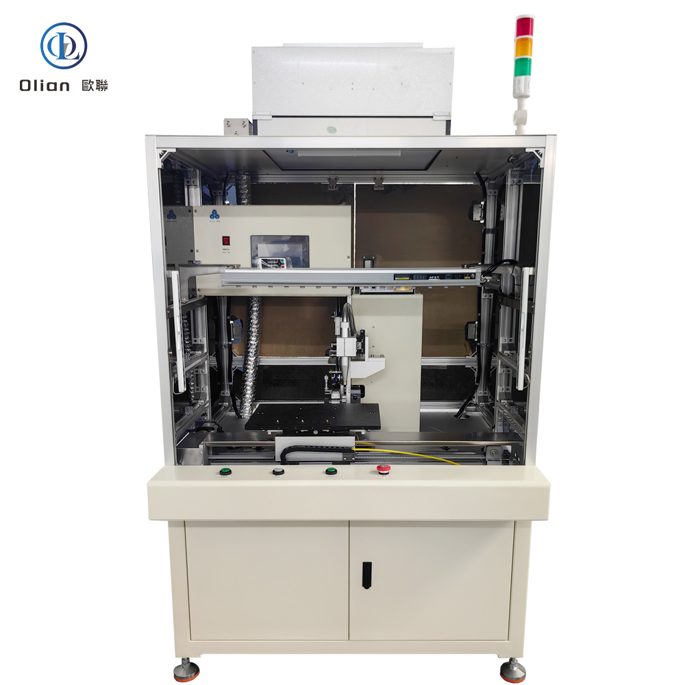
Integrated Solvent Wiping + In-Situ Plasma Activation System for High-Reliability Display Bonding
The OL-QX17 by Olian Automatic Equipment Co., Ltd. is a semi-automatic, single-station cleaning system engineered specifically for the pre-bond surface preparation of edge-conductive (EC) terminals on rigid LCD panels up to 15.6 inches in diagonal size. It addresses one of the most critical failure points in display module manufacturing—poor ACF (Anisotropic Conductive Film) adhesion—by delivering a dual-stage cleaning process: precision solvent-based mechanical wiping followed immediately by low-temperature atmospheric plasma activation.
Unlike simple cloth-wipe stations or standalone plasma cleaners, the OL-QX17 integrates both technologies into a single, synchronized motion cycle, ensuring that the freshly wiped surface is activated before recontamination can occur—a key factor in achieving consistent, high-yield bonding in automotive, medical, and industrial display applications.
Cleaning Principle & Process Sequence
The machine operates on a linear rightward motion platform that carries the panel under a fixed cleaning head assembly. The full cycle is as follows:
Manual Loading: The operator places the bare (unbonded) LCD panel onto the vacuum-equipped worktable, aligning it using mechanical guides. The terminal edge to be cleaned must face the cleaning head.
Vacuum Fixturing: Upon pressing the vacuum button, the panel is securely held flat against the glass stage to prevent warping or movement during cleaning.
Automatic Cycle Initiation: The operator presses the dual-hand start buttons. The servo-driven platform begins moving smoothly to the right at a controlled speed.
Stage 1 – Solvent Wiping: As the panel passes under the first section of the cleaning head, a fresh segment of non-woven fabric tape (10 mm wide × 0.4 mm thick) is pressed against the terminal area with adjustable force (0.1–0.4 MPa). Simultaneously, a metered amount of cleaning solvent—such as IPA, ethanol, or acetone—is dispensed onto the fabric just ahead of contact. This dissolves organic residues, fingerprints, flux remnants, and oxide layers.
Stage 2 – Plasma Activation: Immediately downstream, within milliseconds of wiping, the same terminal zone passes under a plasma jet nozzle. A high-frequency discharge ionizes ambient air or process gas, generating reactive species (oxygen radicals, ions, UV photons) that:
Remove trace molecular contaminants
Break C–H bonds on surface polymers
Increase surface energy (verified by water contact angle <30°)
Create hydroxyl (–OH) groups for superior ACF wetting
Cycle Completion & Unloading: The platform reaches its end position. The cleaning head retracts. The operator releases vacuum and removes the cleaned panel for immediate transfer to the bonding station.
The entire sequence takes approximately 8–15 seconds, depending on panel length and settings.
Key Components & Specifications
Non-Woven Fabric Roll: Standard dimensions: 10 mm (width) × 50 m (length) × 0.4 mm (thickness) Material: Low-lint, solvent-resistant polyamide or cellulose blend Feed mechanism: Stepper-controlled advance, minimum 2 mm per cycle, user-adjustable via HMI
Plasma System:
Nozzle: Custom-designed spray-type plasma emitter
Electrode: Tungsten-alloy core, rated for 3,000 hours of operation
Discharge Copper Core: High-conductivity copper electrode, also rated 3,000 hours
Power Supply: Integrated high-voltage RF generator (frequency and power not specified in doc; assumed standard 10–30 kHz, 50–200 W range)
Cooling: Passive or forced-air (implied by industrial design)
⚠️ Note: Plasma consumable life (3,000 hours) is indicative and may vary based on duty cycle, ambient humidity, and gas composition.
Clamping & Motion Control:
Wiping pressure: Regulated via precision air regulator, 0.1–0.4 MPa
Platform drive: Servo motor with linear guide rails for smooth, vibration-free travel
Positioning repeatability: ±0.1 mm (inferred from industrial-grade components)
Safety & Diagnostics:
Emergency Stop (EMO): Hardwired safety circuit; cuts servo power and activates mechanical brake
Error Alarms: Triggered for fabric feed failure, plasma ignition fault, or motion obstruction
Status Indication: Three-color tower light (green = ready, yellow = running, red = fault) + audible buzzer
Warning Labels: Applied at pinch points, high-voltage zones, and solvent reservoir areas
OL-CC006 – Fully Automatic Offline COF Trimming Machine with Vision-Guided Die Alignment
The OL-CC006 by Olian Automatic is a fully automatic offline trimming machine designed for high-precision die-based cutting of Chip-on-Film (COF) modules. Unlike manual trimmers, it integrates a machine vision system to automatically align the COF to the cutting die before each stroke—ensuring consistent trimming accuracy even with part placement variation.
This machine is used exclusively for post-bonding mechanical finishing. It does not perform bonding, ACF application, or electrical testing, and operates as a standalone workstation.
Vision-Guided Alignment System
The core innovation of the OL-CC006 is its integrated vision subsystem for precise registration:
Camera: One industrial CCD camera (300,000 pixels)
Lens: 2× coaxial light lens
Field of view: 2.4 mm × 1.8 mm
Lighting: External LED illumination
Image processing: FAST algorithm for rapid pattern recognition
The system captures alignment marks on the COF, calculates positional offset, and either guides the operator or triggers auto-correction (as per configured workflow). This significantly improves trimming yield compared to purely mechanical fixturing.
Fully Automatic Operation Cycle
Operator places the COF module onto the loading stage.
The vision system captures and verifies alignment marks.
If within tolerance, the machine automatically initiates the trimming cycle.
A custom die set performs a single-stroke cut to remove excess flex or carrier frame.
The trimmed part is indexed forward on a conveyor-style output line.
The next position is ready for unloading or downstream handling.
The entire process—from vision check to cut—is automated after initial loading.
COF Output Handling
Unloading method: Linear conveyor (flow line)
Post-trim indexing: Each COF moves to a preset position after cutting
Position offset: Adjustable via HMI to match downstream tray or bin layout
This enables seamless handoff to inspection or packaging stations.
Control System & Interface
Controller: PLC-based logic
Operator interface: Color touchscreen HMI
Safety: Dual-hand start buttons and emergency stop (standard industrial configuration)
All vision parameters, indexing distance, and cycle settings are configurable through the touchscreen.
Key Specifications
Max trimming area: Defined by custom die (machine supports standard COF formats)
Vision accuracy: Sub-micron level (dependent on mark quality and lighting)
Throughput: ~800–1200 pcs/hour (depending on COF size and vision processing time)
Power: Single-phase 220V AC
Compressed air: Required for press actuation (typical: 0.5–0.7 MPa)
(Note: Exact utility specs follow Olian’s standard platform; refer to installation manual for wiring and piping details.)
Applications
Ideal for high-volume or high-precision trimming of:
Bonded COF ICs with tight dimensional tolerances
Automotive display COF modules requiring traceability and repeatability
OLED/LCD panel COFs where edge quality affects final assembly
Rework or repair lines needing consistent re-trimming
Commonly deployed in Tier-1 display module factories and automotive electronics suppliers.
Important Clarifications
Trimming only – not a bonding or testing machine
Requires custom dies – designed per customer COF layout
Offline operation – not integrated into continuous production lines
Vision used for alignment verification, not defect inspection
Designed for rigidly supported COF modules, not loose flex strips
One-year warranty on mechanical, electrical, and vision systems (excludes wear parts such as dies, lenses, or light sources)
On-site service within 72 hours if remote support fails during warranty
One-day hands-on training covering vision calibration, die setup, parameter tuning, and maintenance
Lifetime technical support via phone, email, or remote assistance
Includes one Chinese-language operation manual
Model: OL-CC006 Type: Fully Automatic Vision-Guided COF Trimming Machine Key Features: Die-based cutting + CCD vision alignment + conveyor output Operation: Manual load → Auto vision check → Auto trim → Auto index Max Panel Compatibility: Standard COF modules (size defined by die)
The OL-COF-03A by Olian Automatic is a semi-automatic offline trimming machine designed for precision die-based cutting of Chip-on-Flex (COF) modules before bonding. It removes excess flex material or trims carrier frames from COF assemblies using custom-made dies, ensuring clean edges and consistent geometry for downstream assembly or packaging.
This machine is intended for post-bonding finishing only—it does not perform bonding, ACF application, or electrical testing.
Operation Principle
The OL-COF-03A uses a mechanical press actuated by dual-hand start buttons to drive a custom die set. The operator manually loads the COF module into the die fixture, presses both start buttons simultaneously, and the upper die descends to trim the part in a single stroke.
Cycle control: Fully mechanical with safety interlock
Actuation: Pneumatic-assisted press (implied by standard industrial design)
Tooling: Custom-made male/female dies, tailored to specific COF layout
Each die set is application-specific and must be ordered separately or fabricated per customer drawing.
Key Components & Safety Features
Start buttons: Two Φ24 push buttons, requiring simultaneous press for operation
Emergency stop: Φ22 mushroom-type switch for immediate shutdown
Die mounting platform: Rigid steel frame for stable cutting force
Manual loading/unloading: Operator places and retrieves parts by hand
The dual-hand start ensures hands are clear of the die area during operation, complying with basic machine safety standards.
Performance & Specifications
Max trimming area: Compatible with standard COF modules up to typical panel sizes (exact dimensions defined by die)
Repeatability: High, limited only by die precision and operator placement
Throughput: ~600–1000 pcs/hour (depending on operator skill and part complexity)
Power: Standard industrial single-phase 220V AC
Air supply: Required for press actuation (typical: 0.5–0.7 MPa)
Applications
Ideal for:
Trimming excess polyimide from COF ICs in reels
Cutting carrier tabs or tie-bars from COF strips
Final shaping of COF modules before panel integration
Repair or rework stations in display module assembly lines
Commonly used in LCD, OLED, and automotive display manufacturing.
Important Clarifications
Not a bonding machine – performs mechanical trimming only
Requires custom dies – not included unless specified
No vision system, no automation feed – fully manual loading
Offline operation – not integrated into inline production lines
Training, Warranty & Support
Olian Automatic provides full lifecycle support:
One-year warranty on mechanical and electrical components (excludes wear parts such as dies or seals)
On-site service within 72 hours if remote troubleshooting fails during warranty
One-day hands-on training covering safe operation, die change procedure, and maintenance
Lifetime technical support via phone or email
Includes one Chinese-language operation manual
Model: OL-COF-03A Function: Semi-Automatic Die-Based COF Trimming Operation: Manual load → Dual-hand start → Single-stroke trim Key Advantage: Simple, robust, and cost-effective finishing for COF modules