ACF Bonding Machine Manufacturer for LCD Display Production
Discover how ACF bonding machines drive LCD/OLED/MINI LED/Microled/COP… display production — from COG/COF/COP/FOG/FOB/FOP/FOF/OLB bonding processes to choosing the right manufacturer. Explore bonding-machine.com for industry-leading solutions, technical specifications, and expert guidance on anisotropic conductive film bonding equipment.
ACF Bonding Machine Manufacturer for LCD Display Production: The Complete Guide to Choosing the Right Equipment
📌 Quick Navigation
What Is ACF Bonding and Why Does It Matter?
The Critical Role of ACF Bonding Machines in LCD Display Production
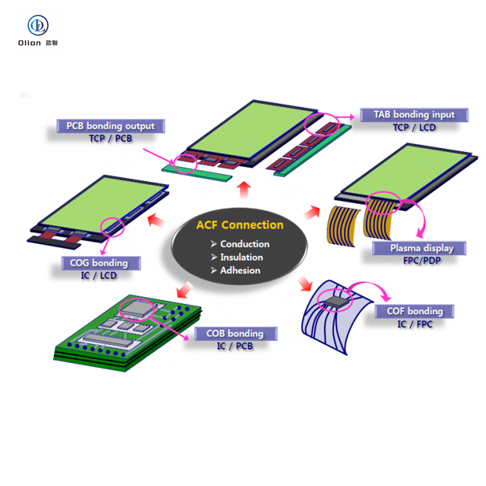
Types of ACF Bonding Processes: COG, COF, FOG Explained
Key Technical Specifications to Evaluate
How to Choose the Right ACF Bonding Machine Manufacturer
bonding-machine.com: Your Trusted ACF Bonding Equipment Partner
Industry Trends & Future Outlook
Frequently Asked Questions (FAQ)
What Is ACF Bonding and Why Does It Matter?
In the world of LCD and OLED display manufacturing, there’s a microscopic process that makes every screen you use possible — ACF bonding.
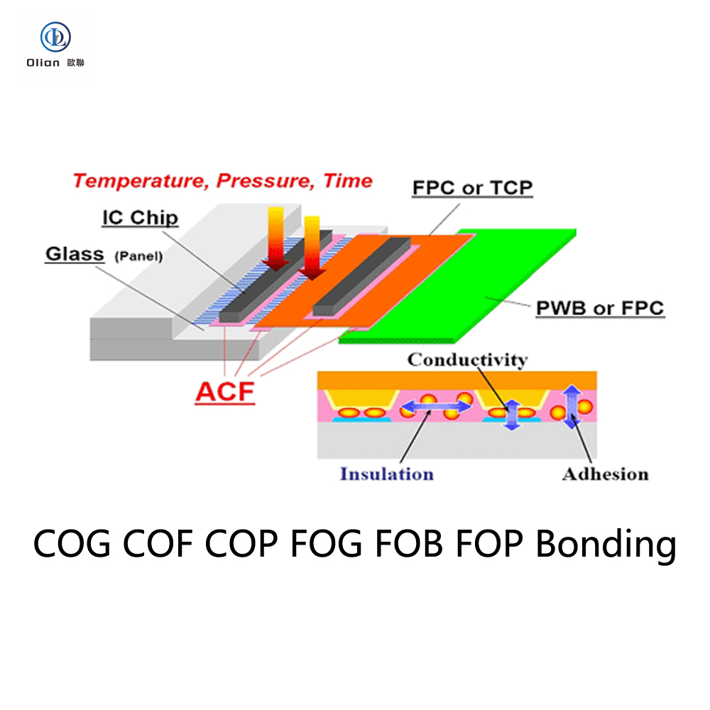
ACF stands for Anisotropic Conductive Film — a specialized adhesive material that conducts electricity vertically (through its thickness) while remaining electrically insulating horizontally (across its surface). Originally developed by Sony Chemical (now Dexerials) in 1977, ACF has become the indispensable “neural synapse” of modern display panels, enabling electrical connections between driver ICs, flexible printed circuits (FPCs), and glass substrates at pitches as fine as 30 micrometers or below.
Think of it this way: within an area roughly the size of a fingernail, hundreds of electrical contacts must be simultaneously connected with micron-level precision — that’s exactly what ACF bonding achieves. Without this technology, the smartphones, tablets, laptops, televisions, automotive displays, and industrial HMI screens we rely on every day simply couldn’t exist.
And the machine that makes this process happen? That’s the ACF bonding machine — the precision equipment that applies temperature, pressure, and alignment control to create reliable, repeatable electrical interconnections using ACF material.
The Critical Role of ACF Bonding Machines in LCD Display Production
LCD display production is a multi-stage manufacturing process where the bonding stage is arguably the most precision-demanding step. Here’s where ACF bonding machines fit in the production flow:
LCD Module Assembly Process Flow
Stage
Process
Equipment Category
1
Glass substrate cleaning
Cleaning equipment
2
ACF film lamination (attach ACF to glass)
ACF bonding machine (lamination unit)
3
Driver IC bonding (COG — Chip on Glass)
ACF bonding machine (COG bonder)
4
FPC bonding (FOG — Film/FPC on Glass)
ACF bonding machine (FOG bonder)
5
Protective sealing (silicone dispensing)
Dispensing equipment
6
Light-shielding tape application
Tape attaching equipment
7
Backlight unit (BLU) assembly
BLU assembly equipment
8
Final inspection & testing
Inspection equipment
As the table shows, ACF bonding machines are involved in at least 2–3 critical stages of LCD module assembly. The quality of bonding directly determines:
✅ Display image stability — no flickering, line defects, or dead pixels
✅ Signal transmission reliability — consistent electrical conductivity at every contact point
✅ Product lifespan — resistance to thermal cycling, mechanical stress, and environmental aging
✅ Yield rate — reducing rework and scrap directly improves production economics
A single bonding defect — a misaligned IC, insufficient ACF compression, or a trapped particle short — can render an entire display panel defective. This makes the choice of ACF bonding machine manufacturer a strategic production decision, not merely a procurement task.
Types of ACF Bonding Processes: COG, COF, FOG Explained
Understanding the different bonding configurations is essential when selecting equipment. Here’s a detailed breakdown:
1. COG (Chip on Glass) Bonding
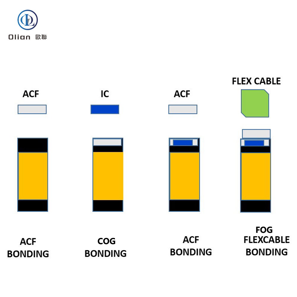
COG bonding attaches a bare driver IC chip directly onto the ITO (Indium Tin Oxide) electrode pads on the LCD glass substrate using ACF as the interconnect medium.
Process Steps:
ACF film is laminated onto the glass bonding area
The driver IC is aligned to the glass electrode pads using a high-precision vision alignment system
Pre-bonding (temporary attach) with low pressure
Main bonding with controlled temperature (typically 180–220°C), pressure (typically 15–30 MPa), and time (typically 8–15 seconds)
ACF resin thermosets, conductive particles are compressed to form vertical electrical pathways
Key Challenges:
Pin pitch down to 30 μm or finer requires sub-micron alignment accuracy
Uneven pressure distribution causes connection reliability issues
Thermal management must prevent glass substrate stress
2. COF (Chip on Film/FPC) Bonding
COF bonding mounts the driver IC onto a flexible printed circuit (FPC) film first, then the COF package is bonded to the glass substrate. This configuration is increasingly preferred for:
High-resolution displays with narrow bezels
Foldable/flexible OLED displays
Displays requiring bendable interconnects
Advantages over COG:
The IC can be bent around the display edge → narrower bezel
Better thermal dissipation through the FPC substrate
Easier repair — the entire COF module can be replaced
3. FOG (FPC on Glass) Bonding
FOG bonding connects the flexible printed circuit board (FPC) to the glass substrate terminal area. This is the signal bridge between the display panel and the external system (motherboard, T-CON board, etc.).
Process Flow (after COG is completed):
Glass terminal area is cleaned
ACF is laminated onto the glass bonding pads
FPC is aligned to the glass pads
Pre-bond → Main bond (thermocompression)
FOG is often the final electrical interconnection step before the LCD module enters final assembly and testing.
Comparison Table: COG vs COF vs FOG
Parameter
COG
COF
FOG
Bonded Component
Bare IC chip
IC-on-FPC package
FPC alone
Bonded To
Glass substrate
Glass substrate
Glass substrate
Bezel Impact
Wider (IC on surface)
Narrower (IC bends around edge)
Minimal (FPC at edge)
Pin Pitch
Finest (down to ~30 μm)
Fine (~40–60 μm)
Moderate (~80–150 μm)
Alignment Accuracy Required
±2–5 μm
±2–5 μm
±15–30 μm
Typical Applications
Standard LCDs, TN/STN
High-res LCD, OLED, foldable
All LCD/OLED modules
Repairability
Difficult (direct on glass)
Moderate (replace COF module)
Moderate
Equipment Needed
COG bonding machine
COF bonding machine
FOG bonding machine
Key Technical Specifications to Evaluate
When comparing ACF bonding machines from different manufacturers, these are the non-negotiable specifications that determine production capability:
🔧 Alignment Accuracy
Grade
Alignment Accuracy
Suitable For
Standard
±15 μm
FOG bonding, moderate-pitch applications
High-Precision
±5 μm
COF bonding, fine-pitch LCD/OLED
Ultra-High-Precision
±2 μm or better
COG bonding, finest pitch ICs
Tip from bonding-machine.com: Always verify alignment accuracy under actual production conditions (not just laboratory specs). Request a live demonstration with your specific product dimensions.
🌡️ Temperature Control
Temperature range: Typically 100–280°C
Temperature uniformity across bonding head: ±2°C or better
Ramp-up speed: Fast heating reduces process time and ACF pre-curing risk
Temperature measurement: Thermocouple embedded in bonding tool vs. infrared sensing
Precision temperature control is critical because ACF’s conductive particles must be compressed at the exact thermosetting temperature — too hot causes ACF degradation, too cold means incomplete curing and unreliable connections.
💪 Pressure Control
Pressure range: 2–5 MPa (adjustable for different ACF types and substrates)
Pressure uniformity: ±5% or better across bonding area
Parallelism of bonding head: Critical for uniform particle compression
Force measurement: Load cell-based real-time monitoring preferred
⏱️ Process Time & throughput
Single bond cycle time: 6–20 seconds (main bond)
UPH (Units Per Hour): Ranges from 300 to 1,200+ depending on machine configuration
Pre-bond + Main-bond sequential time: Total cycle including alignment, pre-bond, main-bond, and cooling
👁️ Vision Alignment System
The vision system is the “eyes” of the bonding machine. Key parameters:
Camera resolution: Minimum 2 megapixels; 5+ MP for ultra-fine pitch
Magnification: Adjustable (typically 2x–10x)
Alignment mark recognition: Support for multiple mark types (cross, circle, L-shape, custom)
💡 A machine that costs 20% more but delivers 3% higher yield can save hundreds of thousands of dollars annually on a high-volume production line.
Shenzhen Olian(bonding-machine.com): Your Trusted ACF Bonding Equipment Partner
At Shenzhen olian (bonding-machine.com), we understand that ACF bonding isn’t just a mechanical process — it’s the heart of display manufacturing. Our commitment goes beyond selling machines; we deliver complete bonding solutions.
What Sets bonding-machine.com Apart
🎯 Comprehensive Product Line
We offer ACF bonding machines covering the full spectrum of display production needs:
±15 μm alignment, high throughput, multi-FPC bonding capability
ACF-L Series
ACF Lamination
Pre-bond ACF attachment, high accuracy film positioning
Multi Series
Multi-function
COG+FOG or COF+FOG combined, flexible production line configuration
🔬 Deep Process Expertise
We don’t just deliver hardware. Our team of process engineers provides:
ACF bonding recipe development — optimized temperature/pressure/time parameters for specific ACF materials (Dexerials, Resonac, Hitachi Chemicals, and Chinese domestic ACF brands)
New product introduction (NPI) support — from first article bonding through production qualification
Yield improvement consulting — systematic defect analysis and process optimization
🌍 Global Service Network
Fast response: 24/7 remote technical support
On-site service: Engineers available for installation, training, and troubleshooting
Regional offices: Service hubs in key display manufacturing regions
Spare parts: Local inventory for critical components
🏭 Proven Track Record
Our machines are running in production lines at display manufacturers serving:
Smartphone and tablet LCD/OLED panels
Automotive infotainment and instrument cluster displays
Industrial HMI and medical display modules
Television and large-format display panels
Wearable and IoT device displays
Industry Trends & Future Outlook
The ACF bonding equipment industry is evolving rapidly alongside display technology advances. Here are the key trends shaping the future:
1. Finer Pitch, Higher Precision
As display resolutions increase (4K, 8K, and beyond), driver IC pin pitches continue shrinking. The industry is moving from 40 μm pitch toward 20 μm and below, requiring bonding machines with:
Alignment accuracy of ±2 μm or better
Higher-resolution vision systems (8+ MP cameras)
More sophisticated alignment algorithms with AI-assisted pattern recognition
2. Foldable & Flexible Display Bonding
Foldable OLED displays (used in smartphones and emerging foldable laptops) demand:
COF bonding as the primary configuration
Bonding machines capable of handling ultra-thin flexible substrates
Specialized ACF materials with enhanced bend reliability
New process parameters for flexible substrate bonding (lower temperature to protect flexible materials)
3. Mini LED & Micro LED Backlight Bonding
Mini LED and Micro LED displays require mass transfer bonding — connecting thousands of tiny LED chips to the substrate. This creates demand for:
High-speed multi-head bonding machines
Gang bonding (simultaneous bonding of multiple chips)
Specialized ACF or alternative interconnect materials
4. Automation & Smart Manufacturing
Industry 4.0 integration in bonding equipment includes:
MES (Manufacturing Execution System) connectivity — real-time production data upload
SPC (Statistical Process Control) — automatic monitoring of bonding parameters
Predictive maintenance — AI-based analysis of machine health data
Digital twin — virtual machine models for process simulation and optimization
5. Domestic ACF Material Adoption
With China now the world’s largest LCD panel producer, domestic ACF material suppliers are rapidly gaining market share (domestic ACF adoption rate has risen to approximately 25%). Bonding machines must be compatible with:
Both Japanese premium ACF (Dexerials, Resonac) and Chinese domestic alternatives
Different ACF specifications (thickness, particle size, curing temperature)
Flexible recipe management for quick material changeover
Frequently Asked Questions (FAQ)
Q1: What is the difference between ACF bonding and soldering?
A: ACF bonding uses anisotropic conductive film adhesive to create electrical connections through thermocompression, while soldering uses molten metal alloy. ACF bonding offers several advantages for display production:
Lower processing temperature (180–220°C vs. 250+°C for soldering)
No flux residues that could contaminate the display
Simultaneous connection of hundreds of contacts in a single bonding cycle
Suitable for glass substrates that cannot tolerate soldering temperatures
Compatible with fine-pitch connections below 40 μm
Q2: How long does an ACF bonding machine typically last?
A: With proper maintenance, a quality ACF bonding machine has a service life of 8–10 years or more. Key longevity factors include:
Regular calibration (typically monthly)
Bonding head replacement schedule (every 6–12 months depending on usage)
Servo system maintenance
Software updates and alignment system recalibration
Q3: Can one machine handle both COG and FOG bonding?
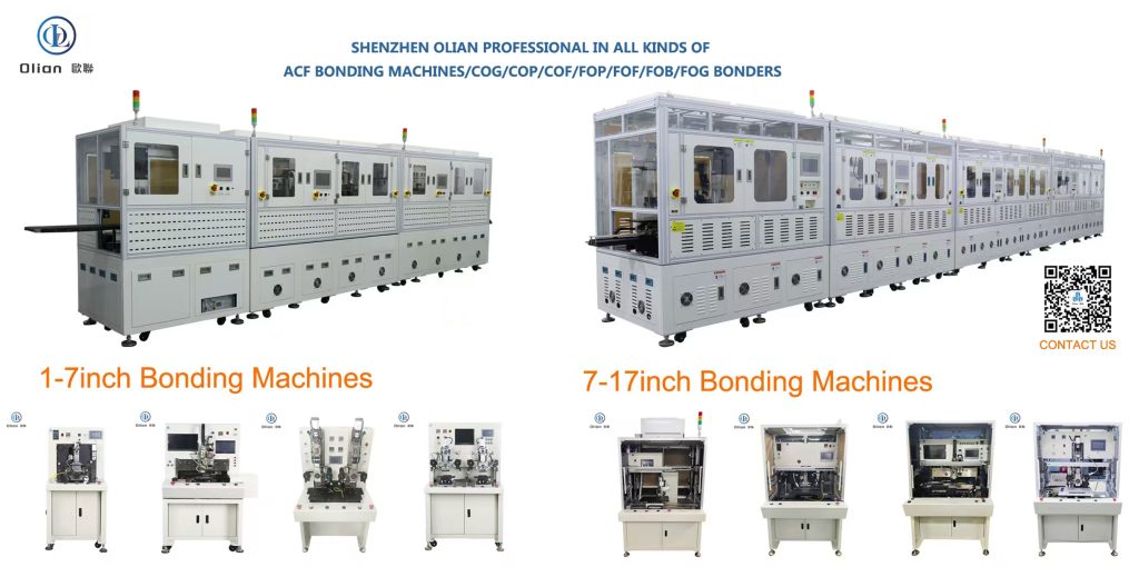
A: Yes. Multi-function bonding machines(full automatic bonding line) can handle both COG and FOG bonding in a single platform, typically through:
Changeable bonding head tooling
Switchable vision system configurations
Adjustable pressure and temperature ranges
This is ideal for factories producing multiple product types with moderate throughput needs.
Q4: What ACF materials are compatible with bonding machines?
A: Modern ACF bonding machines from reputable manufacturers are designed to work with the full range of commercially available ACF films, including:
Dexerials (formerly Sony Chemical) — industry benchmark
Resonac (formerly Hitachi Chemical) — widely used in automotive and industrial displays
Chinese domestic brands — rapidly improving quality, cost-effective alternative
Compatibility depends on ACF thickness (typically 15–40 μm), particle type (nickel, gold-coated, solder), and curing temperature profile. At bonding-machine.com, we test and certify compatibility with major ACF suppliers.
Q5: What is the typical yield rate for ACF bonding?
A: With a properly calibrated machine and optimized process, ACF bonding yield rates typically reach 98–99.5% for standard products. Factors affecting yield include:
ACF material quality and storage conditions
Glass substrate cleanliness
Alignment accuracy and consistency
Pressure and temperature uniformity
Operator skill and process discipline
Our process engineers at bonding-machine.com routinely help customers achieve and maintain >99% yield.
Q6: How do I get a quotation for an ACF bonding machine?
A: Simply contact our team with your production requirements — we’ll provide a detailed quotation including:
Machine configuration recommendation
Process capability assessment for your specific product
Delivery timeline and installation plan
Training and after-sales support package
TCO analysis comparison
Conclusion: The Right Manufacturer Is Your Production Partner
Choosing an ACF bonding machine manufacturer for LCD display production isn’t a transactional purchase — it’s a strategic partnership that directly impacts your product quality, production yield, and competitive position in the display market.
The ideal manufacturer provides not just a machine, but a complete bonding solution: equipment designed for your specific process needs, deep technical expertise in ACF bonding chemistry and physics, responsive after-sales support, and continuous innovation to keep pace with display technology evolution.
At bonding-machine.com, that’s exactly what we deliver — from our comprehensive bonding machine lineup to our process engineering support and global service network.
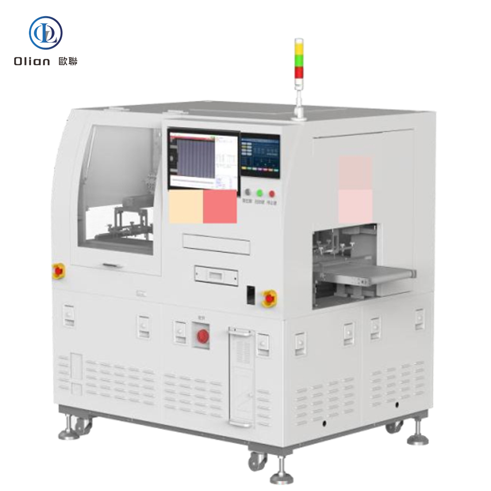
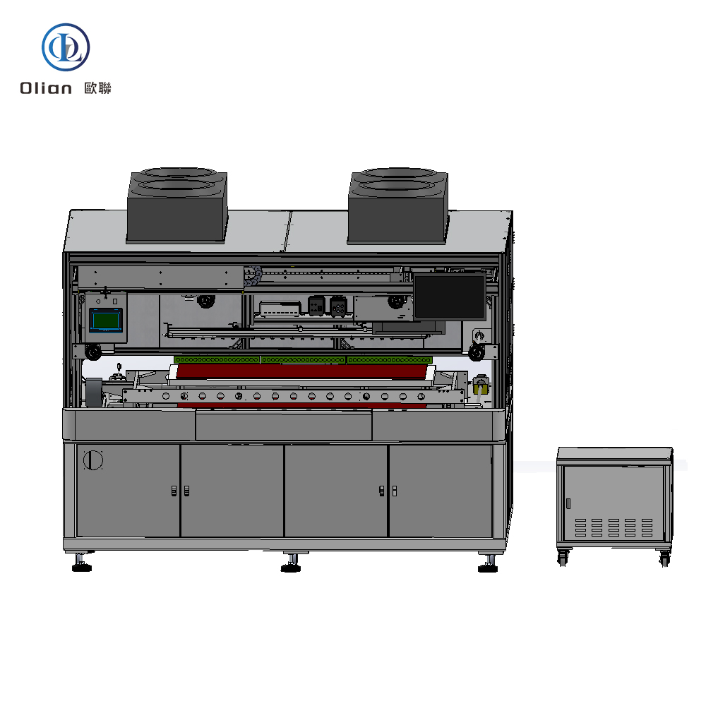
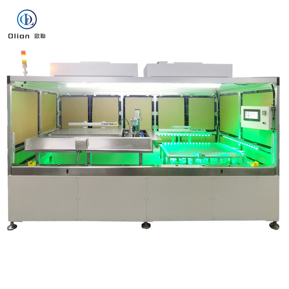
High-Precision Semi-Automatic Mounting for Medium-to-Large Displays
Engineered by Olian Automaic
Developed by Olian Automaic, a Shenzhen-based leader in automation equipment.
Designed for semi-automatic high-precision mounting of flexible circuits (FPC/COF) onto hard boards or flexible films.
Supports display sizes from 7 inches (160×88 mm) to 32 inches (710×400 mm) with material thicknesses of 0.1–1 mm.
Core Functionality
Semi-Automatic Operation: Operators place soft boards (FPC) on the lower platform and hard boards/soft films on the flip platform. The system automates alignment and pressing.
Single-Sided Mounting: Optimized for pre-mounting applications in medium-to-large display manufacturing.
Dual-Platform Design: Flip platform (620×920 mm) and lower platform (620×920 mm) for efficient workflow.
Key Specifications
Platform Size:
Flip platform: 620×920 mm.
Lower platform: 620×920 mm.
Display Compatibility:
Max: 32″ (710×400 mm).
Min: 7″ (160×88 mm).
Thickness: 0.1–1 mm.
FPC/COF Dimensions:
Length/Width: 12–60 mm.
Thickness: 0.1–1 mm.
Step gap between small glass and IC/COF: ≥0.4 mm.
Roller Specifications:
Diameter: φ50 mm.
Length: 648 mm.
Hardness: Standard 60 Shore (customizable).
Production Capacity:
Cycle time: <40 seconds per unit (excluding loading/unloading and cleaning).
Mounting speed: ≥100 mm/s.
Technical Features
Precision Mounting System:
Roller Drive: Servo motor + ball screw + linear guide.
Pressure Control: 0.2–0.4 MPa (adjustable).
Alignment Accuracy: X/Y-axis ≤±0.1 mm (excluding human/material errors).
Adjustable Platforms:
Flip Platform:
Servo-driven Q-axis rotation.
Vacuum fixation (1 mm holes, 1.5 mm grooves).
Lower Platform:
Servo-driven X/Y-axis movement (left/right) + UVW alignment.
Material: Hard-anodized aluminum.
Control System:
PLC: Panasonic.
HMI: Weintek.
Servo Motor: Panasonic.
Performance Metrics
Yield Rate: ≥98% (excluding human error and material defects).
Failure Rate: ≤2% under normal conditions.
Changeover Time:
New models: ≤30 minutes.
Existing models: ≤10 minutes.
Operational Environment
Cleanroom Requirements: Class 100 (ISO 5).
Temperature: 22–27°C.
Humidity: 40–70%.
Power Supply: Single-phase AC 220V, 50/60 Hz, 2000W.
Air Supply: 0.4–0.7 MPa, 150 L/min (φ8 mm transparent tubing).
Vacuum System:
Self-generated vacuum.
Consumption: 66 L/min (yellow tubing).
Safety and Compliance
Emergency Stop: EMO button halts all motion.
Warning Labels: Placed at high-temperature and pinch points.
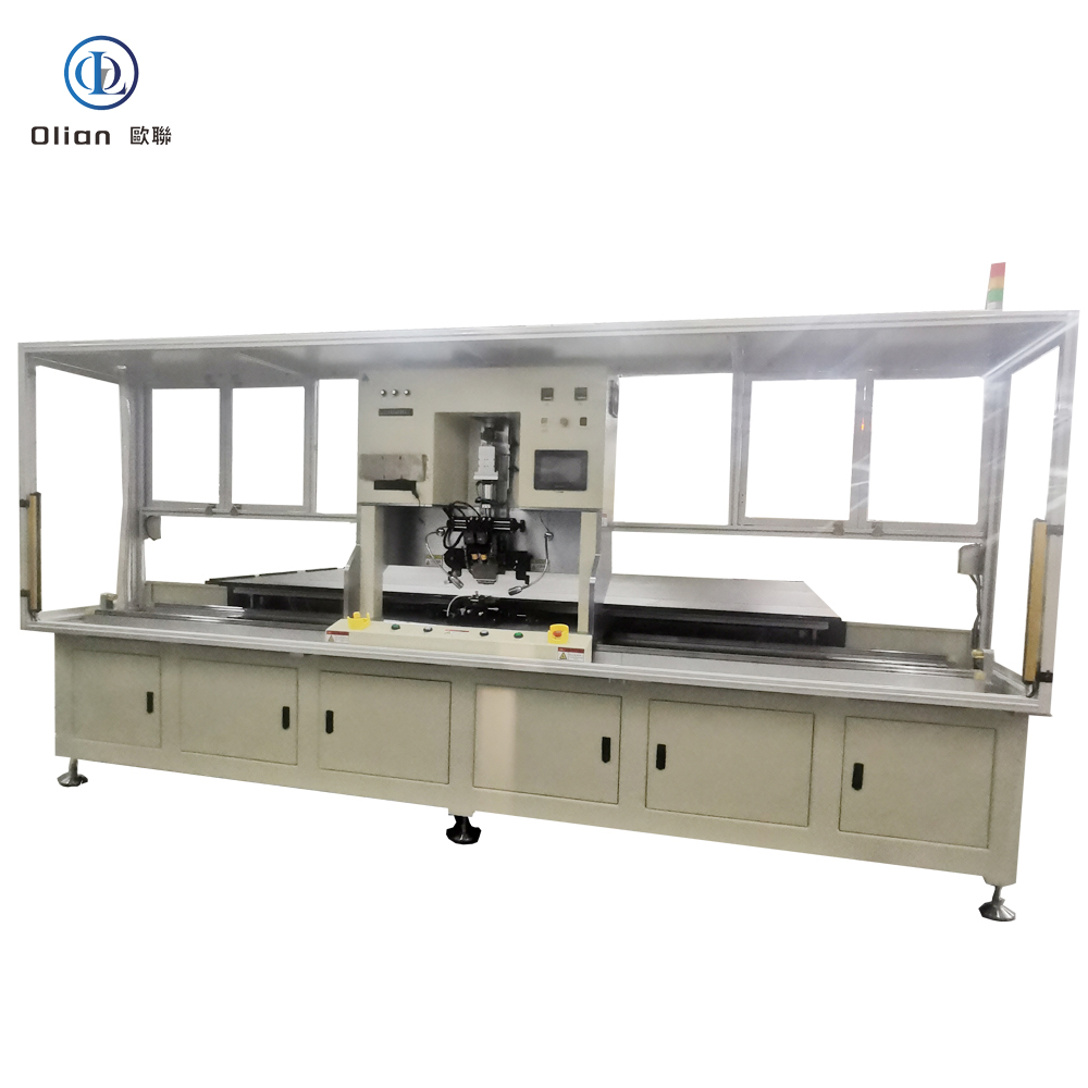
OL-FD065D Up-Down Alignment Constant-Temperature FOG FOB COF Bonder
High-Precision Manual FOG Bonding for 65-Inch Displays
Engineered by Olian Automaic
The OL-FD065D Up-Down Alignment Constant-Temperature FOG Bonder is designed and manufactured by Olian Automaic.
It is a manual flat-panel display (FPD) bonding system, engineered for pre-bonding flexible printed circuits (FPC/COF) and film-on-glass (FOG) applications.
The equipment supports display sizes ranging from 10 inches (200×110 mm) to 65 inches (1450×810 mm), with material thicknesses between 0.1 mm and 1 mm.
Core Functionality
Features manual up-down alignment, allowing operators to precisely position the glass/film and FPC/PCB using Mark points.
After alignment, the system automatically performs the constant-temperature thermocompression bonding process.
Designed as a single-station solution, ideal for small-to-medium volume production and R&D environments.
Key Specifications
Platform Size: Compatible with displays up to 65 inches.
Display Compatibility:
Maximum: 65 inches (1450×810 mm).
Minimum: 10 inches (200×110 mm).
Thickness: 0.1–1 mm.
FPC/COF Dimensions: Length and width from 12 mm to 60 mm; thickness 0.1–1 mm.
Alignment Accuracy:
X-axis: ±0.04 mm.
Y-axis: ±0.05 mm.
Cycle Time: Approximately 8 seconds per unit (excluding manual alignment time).
Temperature Range: Room temperature to 400°C with constant-temperature heating.
Temperature Uniformity: ±5°C across the bonding surface.
Pressure Control: 25–400 N with ±5 N precision.
Technical Features
Dual Imaging System:
Equipped with two 300K-pixel CCD cameras.
Coaxial LED lighting ensures uniform illumination.
Field of view: 1.9×1.4 mm for high-precision alignment.
Adjustable Platforms:
Glass platform with ±2 mm Z-axis adjustment via micrometer.
FPC platform supports manual X/Y/Q/Z-axis adjustment (±5 mm for X/Y/Q; ±2 mm for Z).
Vacuum fixation using 1 mm holes and 1.5 mm grooves for secure substrate holding.
Tungsten Alloy Hot Press Head:
Surface flatness: ≤5 μm (55 mm standard).
Parallelism can be fine-tuned using adjustment screws.
Performance and Efficiency
Product Pass Rate: ≥98% (excluding human error and material defects).
System Failure Rate: ≤2% under normal operating conditions.
Model Changeover Time: Approximately 20 minutes for quick production switching.
Dual Access Levels:
Operator mode: No password required for daily operations.
Engineer mode: Password-protected for advanced parameter settings.
Operational Environment
Power Requirements: Single-phase AC 220V, 50/60 Hz, 1500W.
Air Supply: 0.4–0.7 MPa, 250 L/min using transparent 8 mm tubing.
Vacuum Supply: 36 L/min using yellow tubing.
Operating Conditions: Cleanroom environment with temperature 22–27°C and humidity 40–70%.
After-Sales Support
Warranty: One year (covers non-consumable parts; excludes wear items and damage caused by misuse).
On-Site Training: One-day program covering equipment operation, calibration, and basic troubleshooting.
Technical Service: 72-hour on-site response for issues arising during the warranty period.
Target Applications
Ideal for manufacturers involved in the assembly of LCD and OLED panels.
Commonly used for television displays, industrial monitors, digital signage, and automotive infotainment systems.
Suitable for both prototyping and medium-batch production lines.