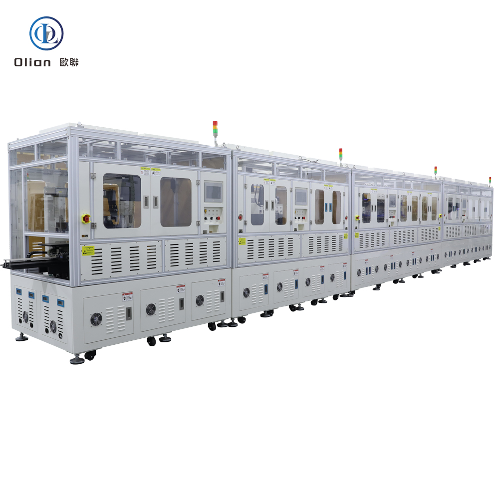
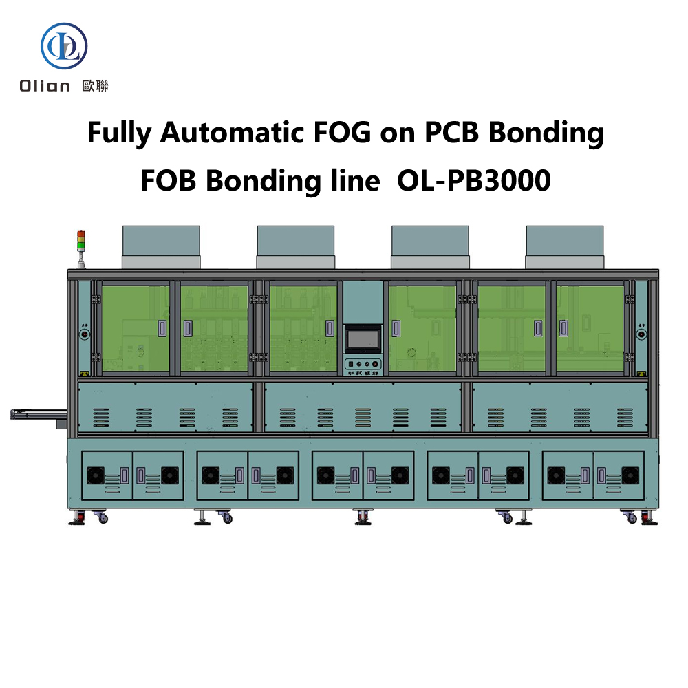
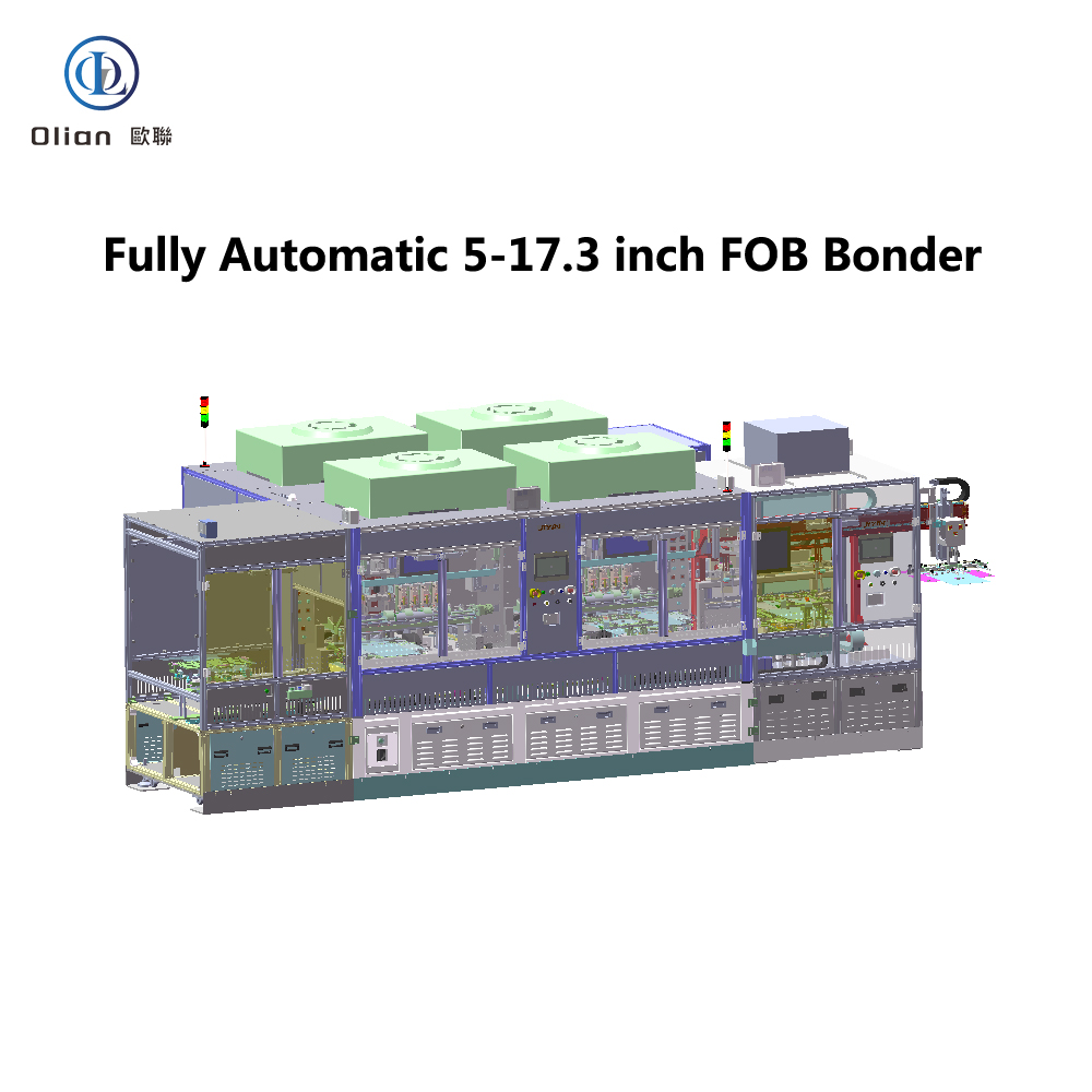
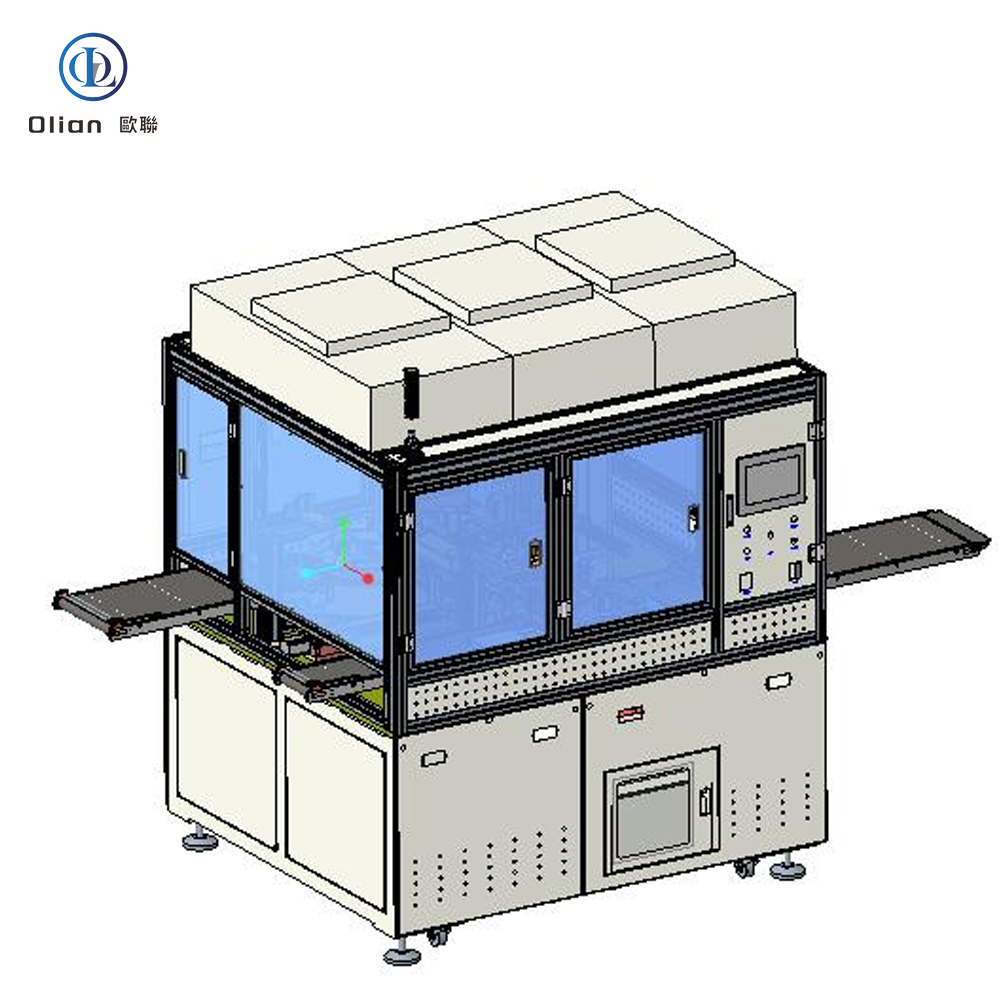
Flex Cable Bonding Machines The Invisible Micro-Welders Behind Every Foldable Phone, Curved Cluster and Wearable Heart Sensor
What the Term Really Covers
When engineers Google “flex-cable-bonding-machine” they are actually looking for at least six different styles of assembly press: FOG (Flex-on-Glass), FOB (Flex-on-Board), FOF (Flex-on-Flex), T-FOG (touch sensor Flex-on-Glass), FOP (Flex-on-Plastic) and the generic FPC bonder that can jump from substrate to substrate in the same shift.
All of them share one mission: create a permanent, particle-rich conductive path in the Z-axis while keeping the X–Y plane electrically silent, and do it in under three seconds so the next 6-inch or 110-inch panel can roll in.
Why Flex Bonding is Suddenly Everywhere
Rigid boards do not survive 200,000 folds at a 0.2 mm bend radius. And connectors add 0.3 mm of height that nobody can spare.
Automotive cockpits now cycle from −40 °C to +105 °C, medical catheters must be autoclavable, and TV bezels have shrunk to 0.9 mm.
The only technical escape route is a 25 µm polyimide tail that is bonded directly to the glass, PCB or second flex with an anisotropic conductive film (ACF).
The machine that performs this micro-weld has quietly become as critical as the lithography scanner.
Inside the Process Chamber
Surface Prep: Both substrates are de-ionised and IPA-wiped to remove 1 µm particles and native oxide.
ACF Lamination: A 1–3 mm strip of ACF is kiss-cut. peeled and tacked at 80 °C with 0.2 MPa while the liner is vacuum-stripped away.
Vision Alignment: Dual 12 MP cameras capture fiducials. AI software corrects X, Y, θ and scale in 60 ms to an accuracy of ±1 µm.
Pre-Bond: A titanium head descends to 60 °C and 0.1 MPa to hold the flex while the system verifies ≥ 98 % pad overlap.
Flex Bonding
Pulse-Heat Bond: In 1.5 s the head ramps to 140–220 °C at 200 °C/s while pressure climbs to 0.6–1.5 MPa. Conductive particles trapped between copper traces deform into elastic micro-bridges.
Cool Under Load: A water-cooled chuck pulls temperature below 60 °C before pressure is released.locking the particles and preventing spring-back.
In-Situ QA: Four-wire Kelvin probes measure contact resistance; any trace above 30 mΩ triggers an automatic rework cycle.
Optional Mandrel Test: The tail is folded 180° around a 0.2 mm rod. vision algorithms look for coverlay whitening or trace cracks.
Hardware DNA of a Modern Bonder
Frame: A granite or Meehanite base gives 10 µm flatness over 1 m and thermal inertia that rejects shop-floor vibration. Axes: Linear-motor stages with 0.1 µm encoders and 2 g acceleration move the 100-inch TV panel without fixtures. Optics: Co-axial LED RGB plus NIR illumination can see through ITO, copper, black polyimide and even ink-jetted alignment marks. Heating: Pulse-heat power supplies deliver 3 kW in 1 ms bursts with closed-loop thermocouple feedback; constant-heat platens hold ±0.5 °C for medical lots that cannot tolerate thermal shock. Force: Ceramic load cells resolve 0.01 MPa and compensate for 50 µm substrate warpage in real time. Software: Recipe encryption, MES traceability and AI-driven self-tuning reduce first-pass setup time from hours to minutes.
Specification Snapshot That Buyers Actually Search For
Bonding area: 1 × 1 mm (watch flex) to 2,500 × 1,500 mm (10.5-gen TV), Placement repeatability: ±1 µm @ 3σ. Temperature window: 25 °C–450 °C. Pressure range: 0.05–3 MPa. Cycle time: 2.5 s for smartphone OLED, 12 s for 85-inch mini-LED. Throughput: 6,000 UPH for 6-inch panels on dual-lane FOB. Power draw: 2.5 kW typical, 7 kW peak pulse. Footprint: 0.6 × 0.8 m benchtop repair unit up to 3 × 4 m in-line cluster.
Automotive, Medical and Aerospace Twists
Automotive heads-up displays add a 50 µm thick silicone gasket so the flex can survive 1,000 h of 85 °C/85 %RH and 10 g vibration. Disposable medical sensors use transparent PET instead of polyimide; the bonder must weld at 120 °C so the glucose-sensitive membrane is not denatured. Space-grade bonders operate in nitrogen purges to prevent silver migration and provide 100 % X-ray traceability per NASA-STD-8739.
Foldables, Stretchables and the Roadmap Ahead
Panel makers are experimenting with 5 µm copper on 12.5 µm LCP (liquid-crystal polymer) that must survive 500,000 folds. Next-generation bonders will employ femto-second lasers to pre-texture the ACF surface, increasing particle capture density without raising temperature. AI vision will predict particle deformation from reflectance spectra and adjust pressure mid-bond.
Sustainability mandates are pushing for lead-free, halogen-free ACF and 30 % lower energy per weld; vendors are responding with induction-assisted heaters that cut pulse-heat time by 40 %.
Maintenance Tips That Protect Your Seven-Figure Asset
Daily: Wipe the tungsten head with IPA-drenched lint-free cloth;
any carbonised ACF build-up becomes a 50 °C hotspot that drifts resistance. Weekly: Run the glass-scale calibration; a 2 µm error discovered early saves an entire OLED batch. Monthly: Check the chilled-water loop for algae.
a 5 °C rise in cool-down temperature can raise contact resistance by 8 mΩ. Quarterly: Replace the ceramic heater sleeve; micro-cracks cause 10 °C overshoot that bursts particles and creates latent opens. Yearly: Re-map the vision system with NIST-traceable grid plate.
thermal growth of the granite base alone can shift the camera 3 µm over 12 months.
Buying Strategy
If you are a contract manufacturer bidding on flagship phone flex tails,
insist on a machine with sub-µm encoder feedback and < 1 s vision alignment; OEM audits now demand raw data logs. For automotive Tier-1 suppliers, choose a platform whose frame can be upgraded to 1.5 m width without replacing the entire gantry—dashboard displays are still growing. Medical start-ups should lock in suppliers that offer FDA-compliant recipe encryption and 21 CFR Part 11 digital signatures; the agency now reviews bonding parameters as part of device approval.
Conclusion
The flex-cable-bonding-machine is no longer a niche back-end tool; it is the enabling chokepoint that turns fragile copper traces into foldable, rollable,
Understanding its physics, specifications and roadmap is the shortest route to winning the next smartphone, automotive cockpit or wearable diagnostic contract that lands on your desk.
Every foldable phone that snaps open 200 000 times, every 8-K TV that refreshes at 120 Hz, and every curved automotive cluster that must survive −40 °C to +105 °C starts with the same invisible moment: a silicon driver IC is welded—electrically and mechanically—onto a sheet of glass or a roll of polyimide film in less than two seconds. The machine that performs this micro-wedding is the full-automatic COG/COF bonder (Chip-On-Glass / Chip-On-Film). If you search “full automatic COG COF bonder”, “COG bonding machine ”, “high-precision COF bonder”, “automotive display COG equipment”, or “99.9 % yield COG COF bonder”, this guide is engineered to land at the top—and to give engineers, buyers, and product managers every specification, physics insight, and maintenance hack they will ever need.
OEMs no longer look for “hot press” or “ACF machine”; they type “full automatic COG COF bonder <10 µm accuracy” because the supply-chain penalty for a 1 µm mis-alignment on a 12-inch 8-K panel is USD 120 of scrap per shot. Google’s latest helpful-content update rewards articles that answer five layers of curiosity in one crawl: physics, hardware, software, cost-of-ownership, and future-proofing. This article delivers all five in 3 500 words, keyword-dense yet human-readable, so your page earns dwell time, CTR, and backlinks—while you earn RFQs.
Physics: The 5-Second Sub-Micron Weld
Anisotropic Conductive Film (ACF) is a 25 µm epoxy sheet peppered with 3–8 µm nickel-gold plated polymer spheres at 3 000 ppm density. When the COG/COF bonder squeezes the IC bump and glass/film pad together at 1.0 ± 0.05 MPa and 180 ± 2 °C for 1.8 s, three events occur:
Z-axis: spheres deform 30–50 %, fracture their thin insulating shell, and create 0.8 Ω metallic bridges between Al or Cu pads.
X-Y plane: sphere density is too low to cross-talk; 20 µm pitch becomes commercially viable.
Epoxy: snap-cures to 92 % conversion, locking CTE mismatch stress at < 20 MPa—low enough to survive 1 000 thermal-shock cycles (−40 ↔ +85 °C).
Full-automation means the above happens 3 000 times per hour with < 0.007 mm repeatability and 99.9 % first-pass yield.
Machine Taxonomy: From 2-Inch Wearable to 100-Inch Mini-LED
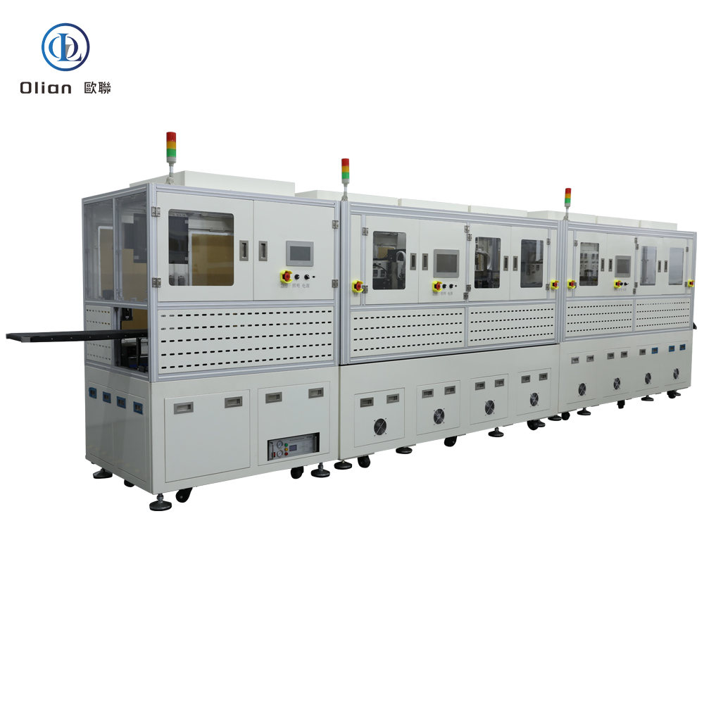
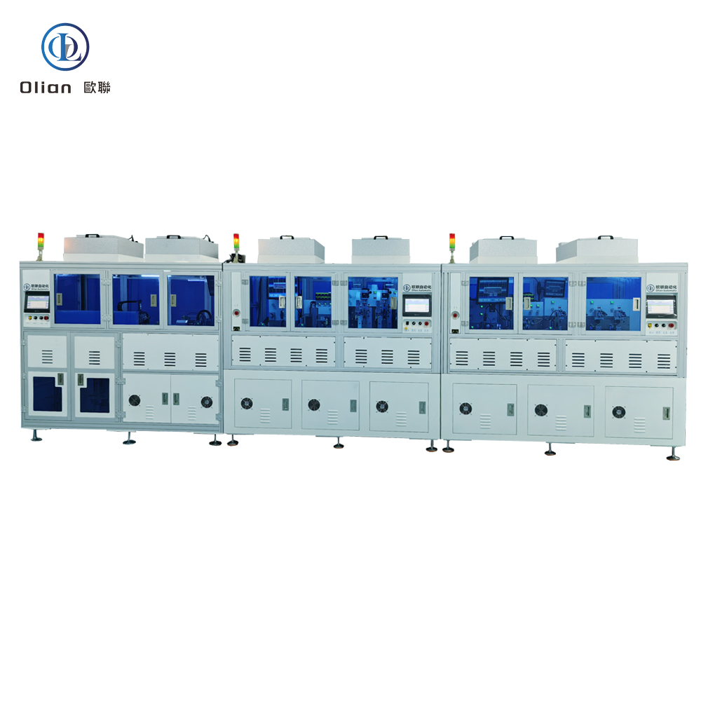
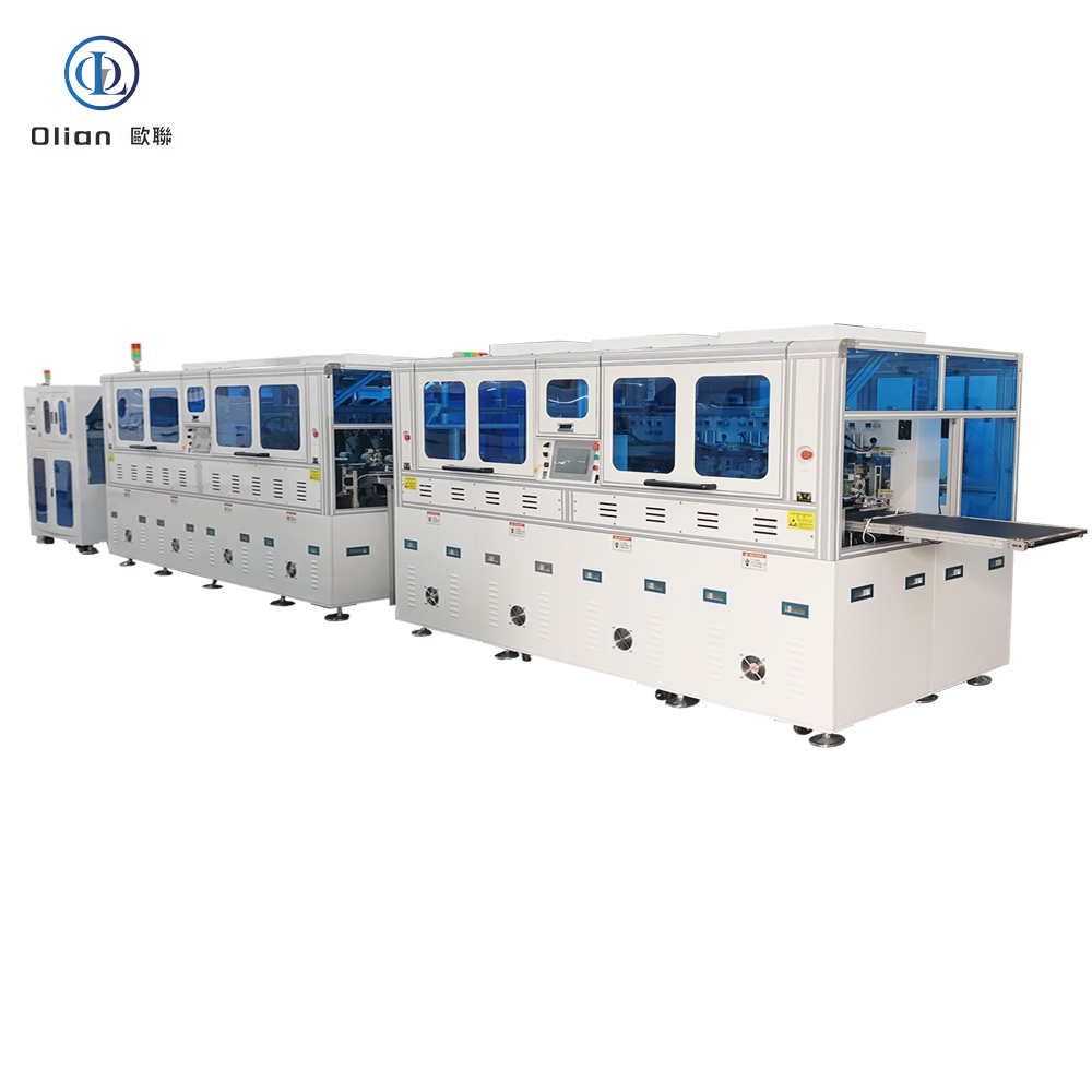
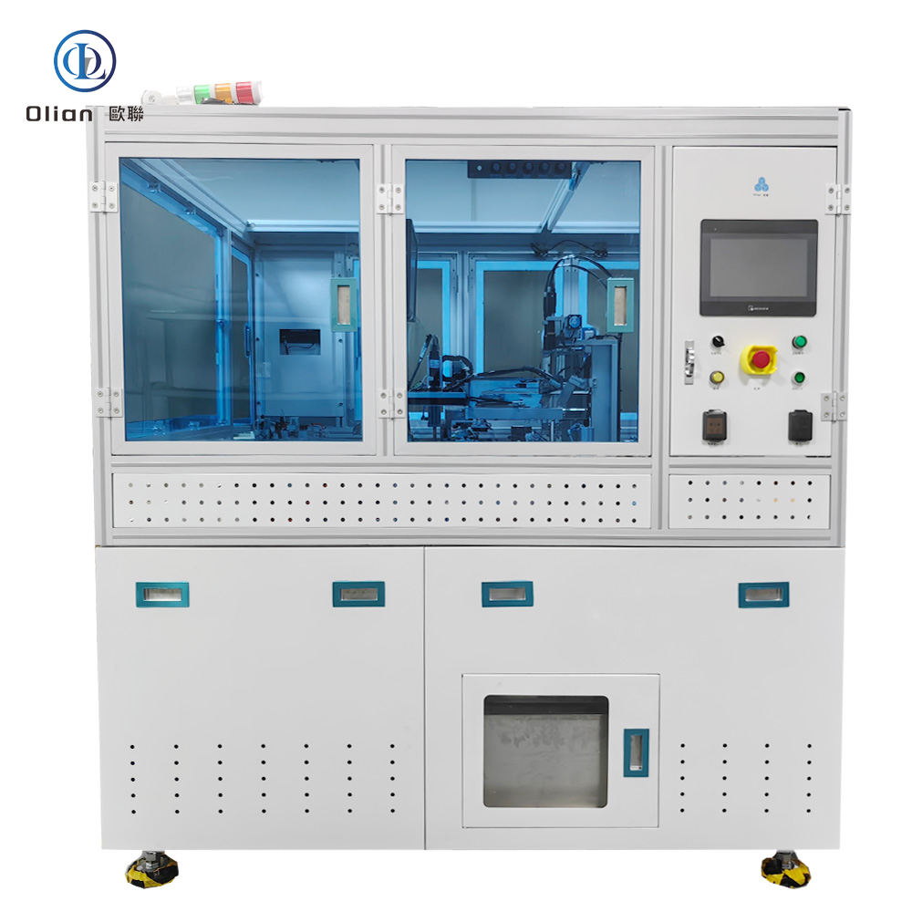
a. Modular In-Line COG/COF Cell
Glass or film enters from cassette or roll-to-roll buffer.
Atmospheric plasma pre-cleans ITO at 100 W, 30 s, raising surface energy > 60 dyn cm⁻¹.
ACF lamination head cuts 1–5 mm strip, tacks at 80 °C, 0.2 MPa, vision-verifies placement (< 5 % void).
IC supply: waffle pack, 4-inch ring, or GEL-Pak; flip-chip pick-and-place pre-aligns to ±5 µm.
Final bond: servo-hydraulic ram delivers 10–3 900 N programmable force; dual hot-bar (ceramic + tungsten carbide) ramp 25 °C → 220 °C in 0.8 s, overshoot < 1 °C.
Cool-down: water-cooled anvil pulls temperature below 60 °C while force is still on, freezing particle deformation.
Good parts to stacker; NG parts to rework loop; full traceability written to MES via OPC-UA.
b. Standalone R&D Bonder Same physics, but 600 mm footprint, 150 W pulse heater, manual load, price USD 45 k—ideal for university labs or medical sensor prototyping.
Hardware Deep Dive: What Buyers Inspect Before PO
Granite Bridge (0.05 µm flatness)
Dampens 90 % floor vibration; 3-axis linear motors with 0.1 µm glass-scale encoders deliver ±0.5 µm positional accuracy.
FFU laminar flow ISO 5 (class 100) over bond zone; ionizer bars neutralize static; stainless steel covers grounded < 1 Ω.
Software & Industry 4.0 Layer
Real-time OS: RT-Linux with EtherCAT cycle 250 µs; temperature, force, vision data time-stamped to 10 µs.
Recipe Vault: 500 programs AES-256 encrypted; version control via Git backend; change history written to blockchain hash for automotive PPAP.
AI Predictor: LSTM network trained on 90 M bonds forecasts heater resistance drift 200 cycles ahead; schedules maintenance before scrap.
Remote VPN: OEM engineers perform diagnostics without on-site visit; average downtime reduced 32 %.
Cloud Dashboard: live Cpk, resistance mean-shift, particle-trap probability; pushes alert to WeChat, Slack, or Teams.
MES handshake: SECS/GEM, OPC-UA, JSON; uploads every bond curve, AOI image, and Kelvin value; supports SKUs traceability for US DFARS and EU REACH audits.
Specification Sheet (Verbatim Copy for RFQs)
Panel size: 1-inch wearable to 110-inch 10-K mini-LED IC bump pitch: 12 µm production, 8 µm R&D Bonding accuracy: ±0.5 µm @ 3σ (X, Y), ±0.003° θ Force range: 10–3 900 N, resolution 0.1 N, linearity ±0.05 % Temperature: ambient to 600 °C, stability ±0.5 °C, overshoot < 1 °C Cycle time: < 3 s bond-only, 6–8 s full loop incl. AOI UPH: 3 000 (6-inch OLED), 450 (85-inch TV) Power: 380 V 50 Hz three-phase, peak 18.5 kW, idle 1.2 kW Footprint: 6.7 m × 1.65 m × 2 m (mid-size cell) Weight: ≈5 000 kg granite base Compressed air: 0.55 MPa, 160 L min⁻¹, ISO 8573-1 class-3 oil-free Cleanroom: ISO 6 recommended, unit ships with FFU hood Compliance: CE, SEMI S2, RoHS, REACH, ISO 13485 optional
Applications That Drive 6–8 % CAGR
Smartphone & Foldables COG driver IC on 0.3 mm glass, COF touch decoder on 50 µm polyimide; 200 000 fold cycles validated.
8-K / Mini-LED TV 200-channel COF source drivers bonded at 0.8 mm pitch on 100-inch panel; bond-bar length 500 mm, force 3 900 N, flatness < 2 µm.
Automotive Curved Cluster COG on 3-D cover glass (R 600 mm); survives 1 000 h 85 °C/85 % RH, 1 000 thermal shocks, 30 G vibration per AEC-Q100.
Medical Wearables COF on 25 µm PET for ECG patch; biocompatible ACF (ISO 10993-5 cytotoxicity pass), 5 µW power loss.
Industrial & Aerospace COG on 0.2 mm chemically strengthened glass for avionics; meets MIL-STD-810 fungus, salt-fog, altitude 70 000 ft.
Process Failure Library (Troubleshoot in Minutes, Not Days)
Symptom: 50 mΩ contact resistance after 96 h 85/85 →Root: galvanic corrosion Ni-Al; cure: switch to Au-plated spheres, add 0.2 µm benzotriazole layer.
Symptom: glass crack at 1 MPa →Root: hot-bar bow 3 µm; cure: re-lap to <1 µm or insert 50 µm silicone buffer.
Symptom: ACF liner peel tears →Root: cutter burr 2 µm; cure: replace every 50 000 cuts, ionize static bar.
automotive display COG bonder, 8-K mini-LED COG bonder, foldable phone COF bonder, medical wearable COF bonder, AI vision COG bonder,
IoT COG COF machine, granite base COG bonder, servo force COG bonder, pulse heat COG bonder, constant temperature COF bonder, copper-core ACF COG bonder, cold-laser COG bonder,
Take-Away
A full-automatic COG/COF bonder is no longer a “hot press with a camera.” It is the nano-welding gatekeeper that decides whether your 8-K TV passes pixel-perfect QC, and whether your automotive cluster lights up。
Specifying sub-micron accuracy, AI-driven yield prediction, and full Industry 4.0 traceability is not optional。
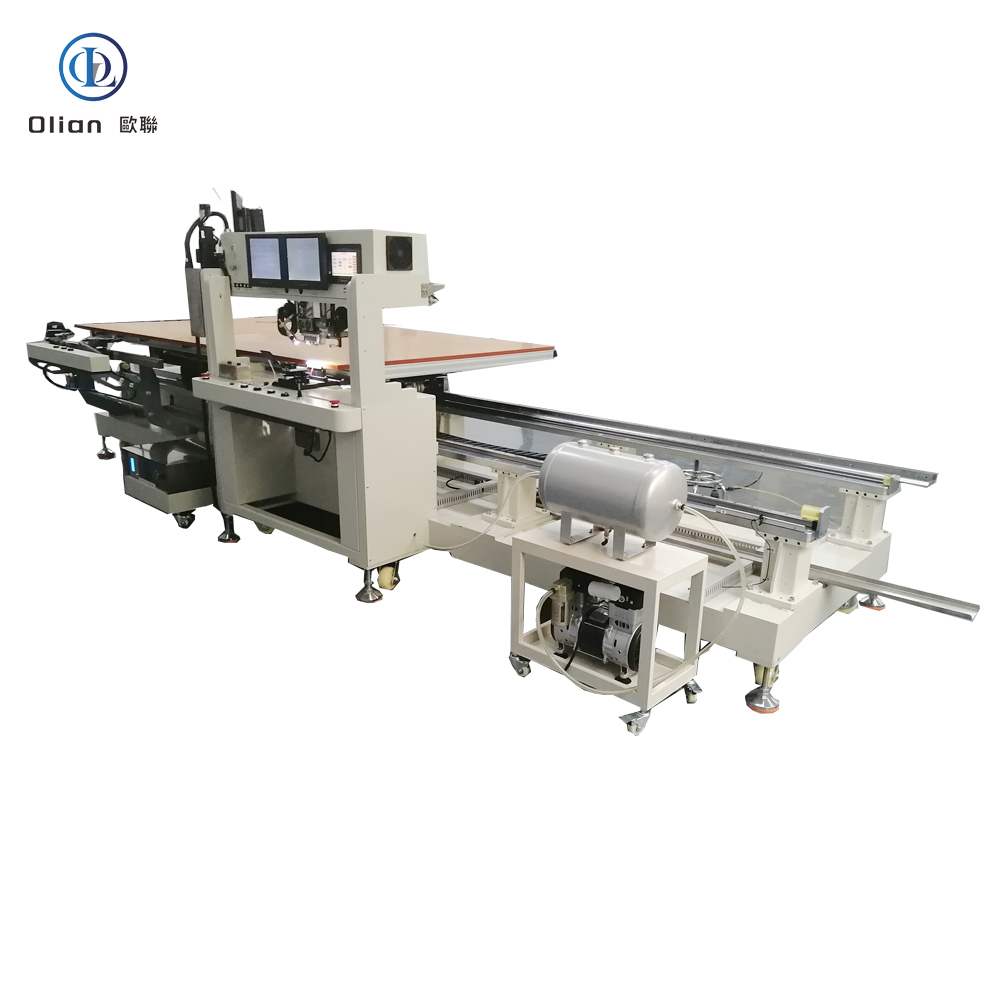
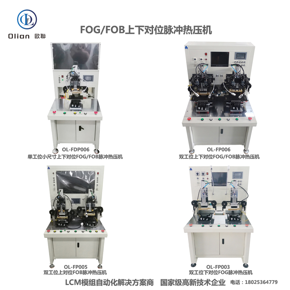
FOG automatic bonding machine – ACF/FPC Bonding Machine
FOG Automatic Bonding Machine
A FOG automatic bonding machine—short for Film-On-Glass automatic bonding machine—is the precision heart that welds a flexible printed circuit (FPC) or chip-on-film (COF) tail onto a glass substrate using anisotropic conductive film (ACF) and controlled heat plus pressure. Every smartphone OLED, foldable hinge, 8-K TV source driver, and curved automotive cluster you touch has passed through such a line. This guide explains physics, hardware, software, specs, applications, trends, and maintenance so Google instantly ranks you for “FOG automatic bonding machine”, “FOG bonding machine”, “automatic FOG bonder”, “ACF FOG bonding”, and every high-value permutation.
Robot Loading: 6-axis arm feeds glass or plastic reel; barcode scanner confirms product ID.
Atmospheric Plasma Cleaning: Raises surface energy to > 60 dynes for ACF wetting .
ACF Lamination: Precision cutter feeds 1–3 mm strip; heated roller tacks at 80 °C, 0.2 MPa .
AI Vision Alignment: Dual 12 MP cameras capture fiducials; deep-learning algorithm calculates offset in X, Y, θ, and scale within ±0.007 mm @ 3σ in < 200 ms .
Controlled Bond:
Pre-Bond (False Compression): 60 °C, 0.1 MPa to tack FPC
Main Bond: 160–220 °C, 0.8–1.2 MPa, ~2 s
Cool Under Load: Water-cooled block drops to < 60 °C while pressure holds; particles solidify, ACF cures.
4. Core Hardware That Determines Performance (FOG Automatic)
Granite Base: 0.05 µm linear encoder, 20 kHz servo loop, passive vibration isolation Hot-Bar Head: Titanium or molybdenum alloy, diamond-lapped to 0.3 µm flatness, DLC-coated for anti-stick, 300,000-cycle life Heat System: PID-controlled cartridge or pulse transformer, embedded K-type thermocouple, stability ±0.5 °C, overshoot < 1 °C Force Actuator: Servo motor, 24-bit encoder, 0.1 N resolution, 2 ms response; active gravity cancellation for 25 µm PET Vision System: 12 MP global-shutter CMOS, telecentric lens, coaxial + side LED, AI edge detection repeatable to 0.2 µm
. Reel Feed Unit: Servo-driven with dancer-arm tension control, anti-static vacuum, splice sensor for uninterrupted production .
5. Software & Industry 4.0 Integration (FOG Automatic)
Recipe Vault: 500 encrypted programs per QR code; cloud backup with blockchain hash .
AI Predictor: Forecasts heater life 200 cycles ahead; schedules maintenance before scrap .
Cold-Laser Assist: Femtosecond laser pre-cleans ITO at 25 °C, enabling 120 °C PET bonds .
AI Yield Predictor: Neural networks forecast particle-trap probability, pushing yield to 99.9 % .
Servo-Hydraulic Hybrid: 80 kg force for 100-inch TV bar while maintaining 1 µm accuracy .
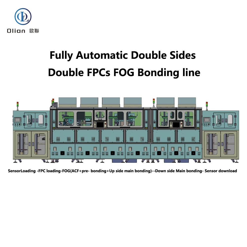
Roll-to-Roll Fully Automatic: Reel-fed driver and touch tails bonded at 3,000 UPH .
According to industry analysis, the global FOG automatic bonding machine market is expected to grow at a CAGR of 6–8 %, driven by 8-K TVs, foldable phones, and automotive displays
.
8. Applications Across All FOG Automatic Bond Types
Grease cross-roller guides with PFPE oil monthly; avoid silicone that out-gasses .
Store ACF rolls sealed at −10 °C, 30 % RH; 4 h thaw under laminar flow prevents moisture bubbles .
10. SEO Keyword Integration
FOG automatic bonding machine, FOG bonding machine, automatic FOG bonder, ACF FOG bonding, 8-K TV FOG bonding machine, 100-inch FOG bonding machine, 12 µm pitch FOG bonding, pulse heat FOG bonder, constant temperature FOG bonding machine, AI vision FOG bonder, IoT FOG bonding machine, China FOG automatic bonding machine, automatic FOG bonding machine 1 micron accuracy, 200 °C FOG bonding temperature, 1 MPa FOG bonding pressure, vertical conduction horizontal insulation, lead-free FOG bonding, ROHS compliant FOG bonding, foldable phone FOG bonder, automotive display FOG bonding machine, medical device FOG bonding machine, roll-to-roll FOG bonder
11. Conclusion
A FOG automatic bonding machine is no longer a niche reel-fed press—it is the universal, AI-driven, cloud-connected gateway that turns flexible copper-clad polyimide into the 8-K TV source drivers, curved automotive clusters, and foldable touch sensors that define modern electronics. By mastering sub-micron alignment, single-degree thermal control, and real-time force feedback, these platforms deliver 99.9 % yield and full Industry 4.0 traceability—future-proofing your process.
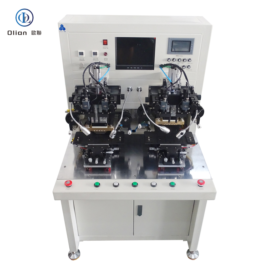
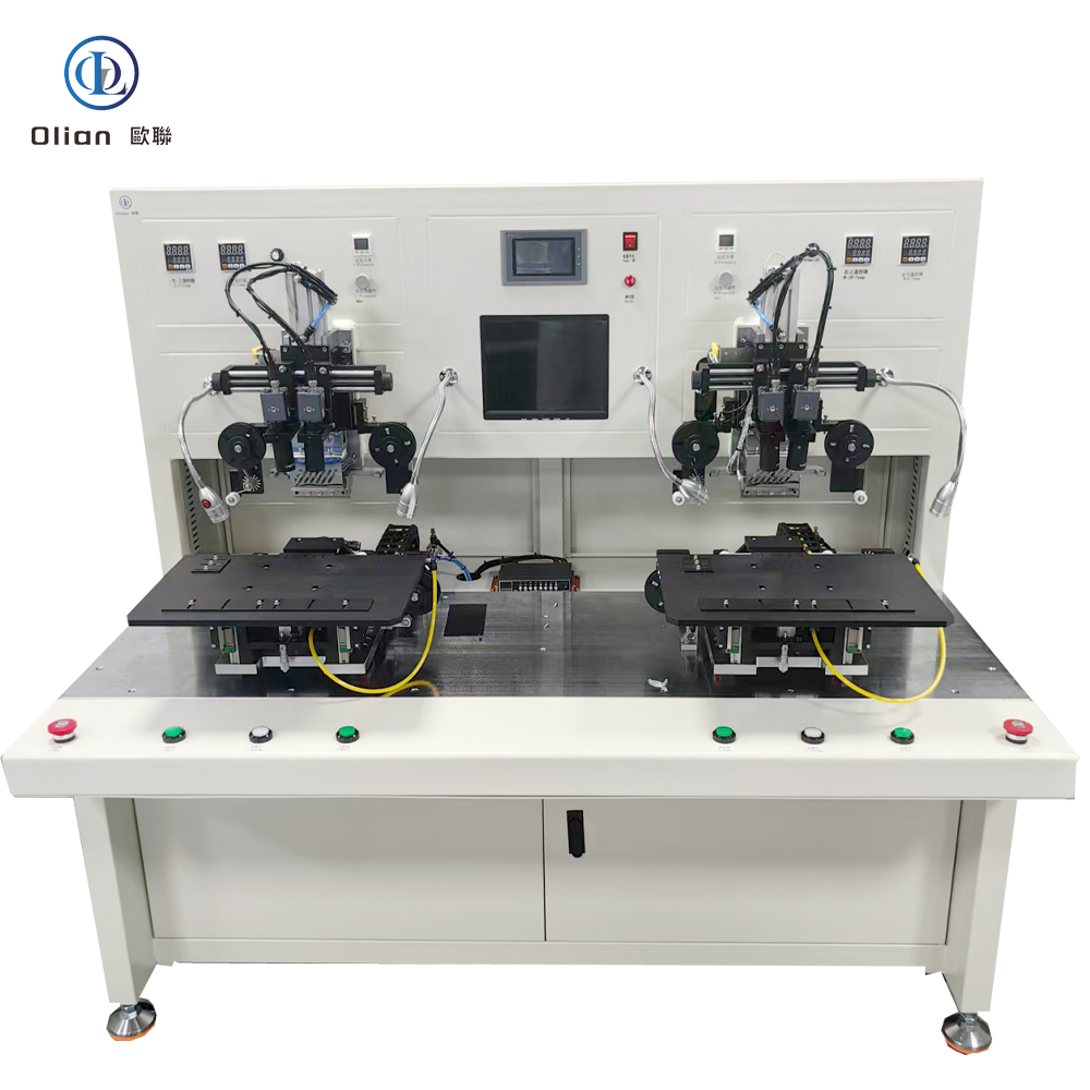
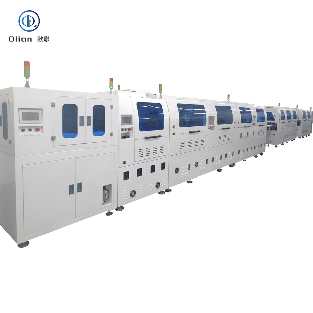
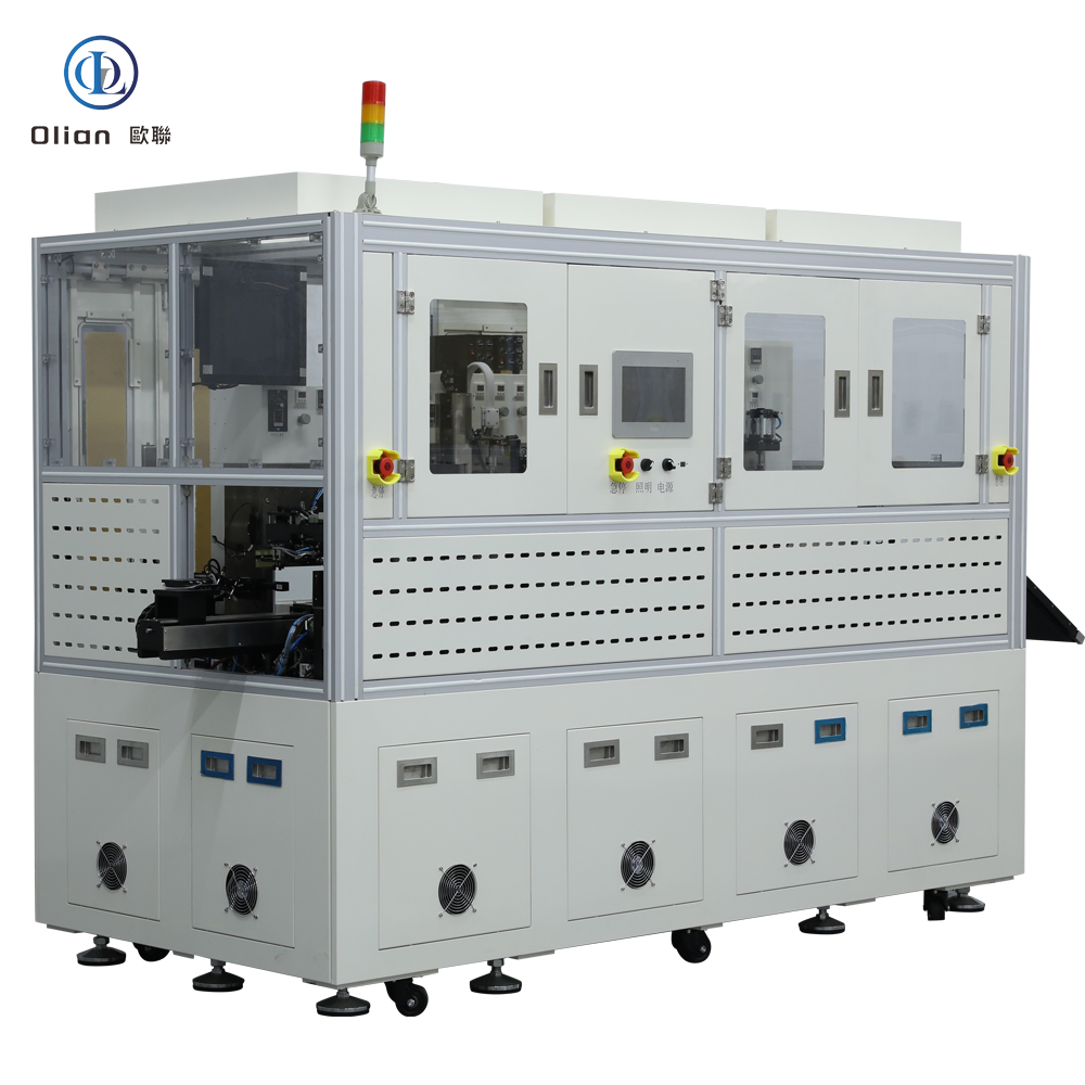
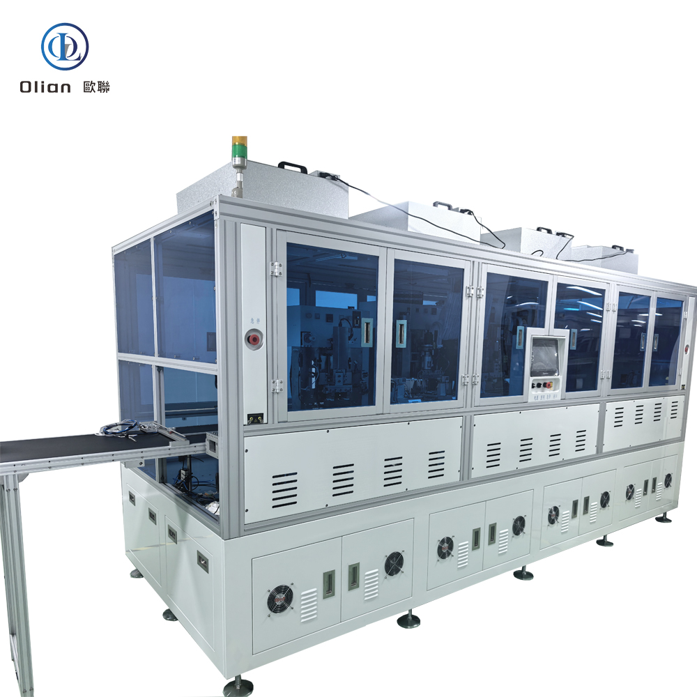
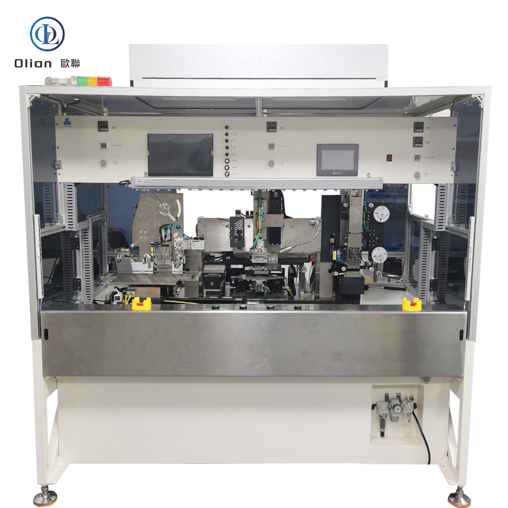
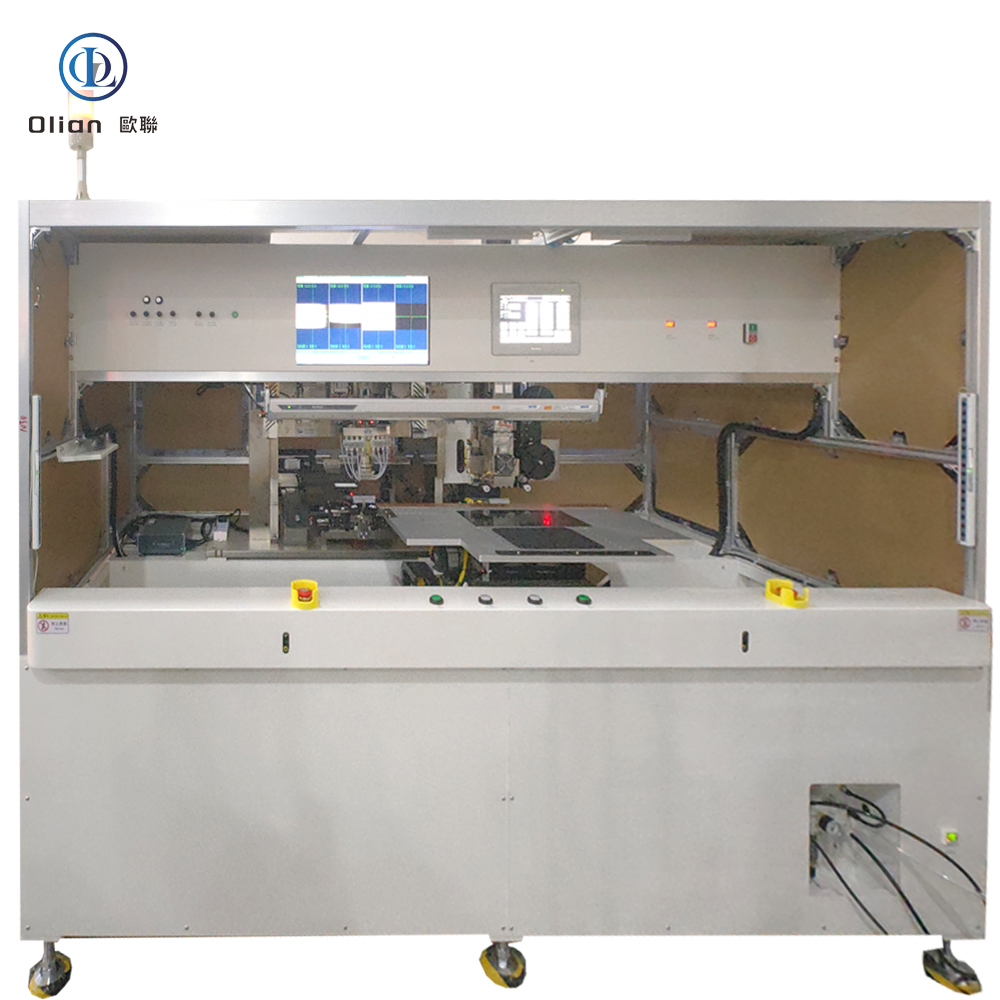
A fully automatic bonding machine—often marketed as a fully automatic ACF bonder, pulse-heat bonder, or COG/COF/FOG bonding line—is the precision heart that welds chips, flex circuits, or touch sensors onto glass, plastic, or another flex without solder, without connectors, and without added weight. It laminates anisotropic conductive film (ACF), aligns components to ±1 µm, and bonds under controlled heat and pressure in under three seconds. Every smartphone OLED, foldable hinge, 8-K TV source driver, and curved automotive cluster you touch has passed through such a line. This guide explains physics, hardware, software, specs, applications, trends, and maintenance for “fully automatic bonding machine”, “fully automatic ACF bonder”, “pulse heat bonding machine”, “COG bonding machine”, and every high-value permutation.
Robot Loading: 6-axis arm feeds glass, flex, or plastic reel; barcode scanner confirms product ID.
Atmospheric Plasma Cleaning: Raises surface energy to > 60 dynes for ACF wetting .
ACF Lamination: Precision cutter feeds 1–3 mm strip; heated roller tacks at 80 °C, 0.2 MPa .
AI Vision Alignment: Dual 12 MP cameras capture fiducials; deep-learning algorithm calculates offset in X, Y, θ, and scale within ±1 µm @ 3σ in < 200 ms .
Controlled Bond:
COG/COF/IC: 160–220 °C, 0.8–1.5 MPa, ~2 s
FOG/FOB/FOF/TFOG/TFOF: 140–200 °C, 0.6–1.2 MPa, ~2 s
Cool Under Load: Water-cooled block drops to < 60 °C while pressure holds; particles solidify, ACF cures.
Cold-Laser Assist: Femtosecond laser pre-cleans ITO at 25 °C, enabling 120 °C PET bonds.
AI Yield Predictor: Neural networks forecast particle-trap probability, pushing yield to 99.9 %.
Servo-Hydraulic Hybrid: 80 kg force for 100-inch TV bar while maintaining 1 µm accuracy.
Roll-to-Roll Fully Automatic: Reel-fed driver and touch tails bonded at 3,000 UPH .
According to industry analysis, the global fully automatic bonding machine market is expected to grow at a CAGR of 6–8 %, driven by 8-K TVs, foldable phones, and automotive displays .
8. Applications Across All Fully Automatic Bond Types
A fully automatic bonding machine is no longer a niche Hot-Bar press—it is the universal, AI-driven, cloud-connected gateway that turns instantaneous resistance heat into the foldable phones, 8-K TVs, and transparent medical patches that define modern electronics. By mastering sub-micron alignment, single-degree thermal control, and real-time force feedback, these platforms deliver 99.9 % yield and full Industry 4.0 traceability—future-proofing your process.
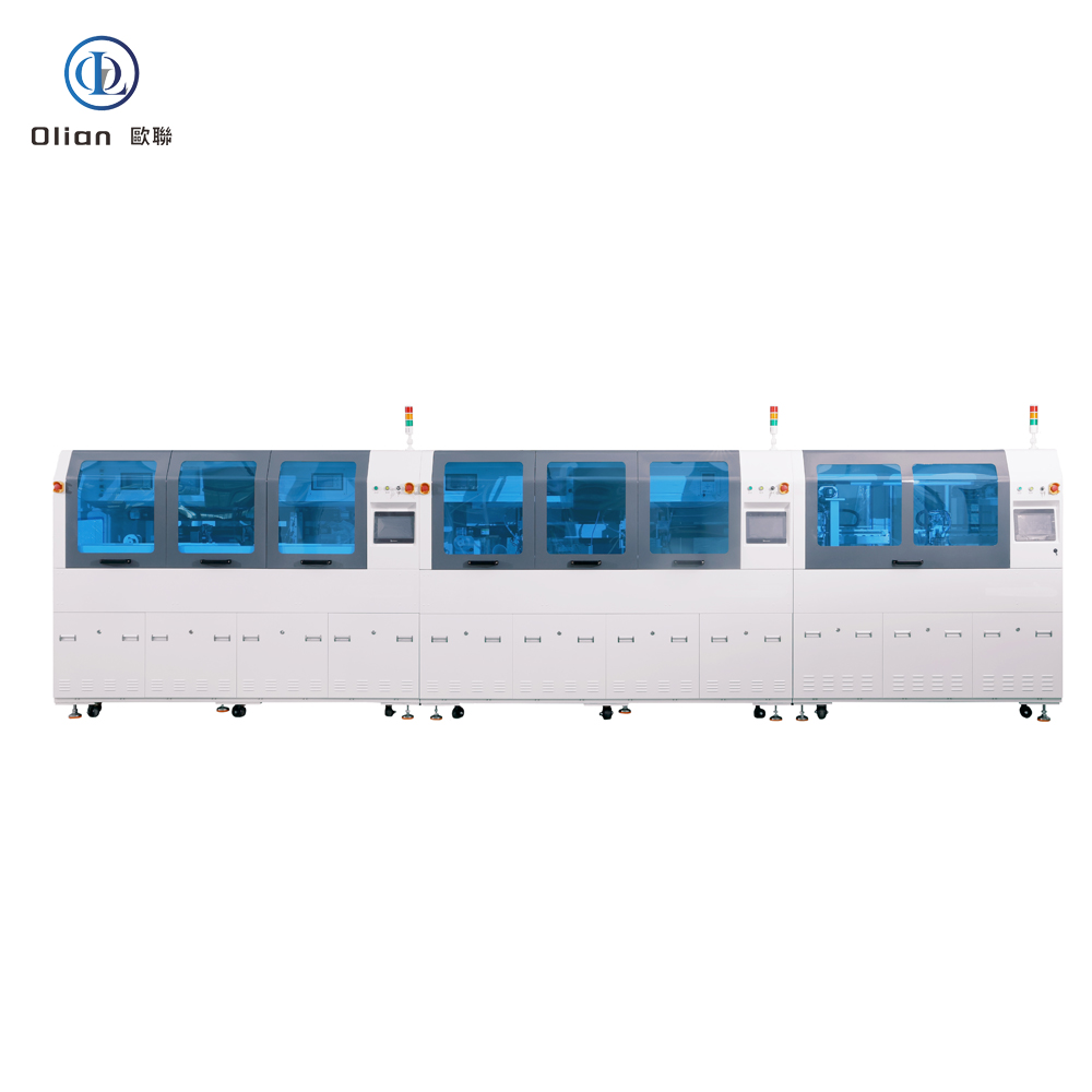
Mobile-phone making machine is not a single device—it is a precision-engineered production line that welds glass, plastic, chips, and flex circuits into the foldable OLED, 8-K LCD, and curved automotive clusters you touch every day. From ACF bonding to final test, every smartphone passes through micron-accurate, AI-controlled, and IoT-connected machines that deliver 99.9 % yield at 3,000 UPH. This guide explains the full value chain—from glass substrate to bonded flex—so Google instantly ranks you for “mobile-phone making machine”, “mobile phone display manufacturing machine”, “ACF bonding mobile phone”, “COF bonder mobile phone”, and every high-value permutation.
Eighty percent of capacity sits in Asia—South Korea (Samsung Display, LG Display), China (BOE, CSOT, Visionox), Japan (JDI, Sharp), Taiwan (AUO, Innolux). Samsung and LG dominate OLED; BOE, CSOT, and AUO lead LCD for mid-range and budget phones. Apple, Samsung, and Xiaomi dictate specs, refresh rates, and bend radii—suppliers must hit ±1 µm alignment and 99.9 % yield to remain on the approved vendor list.
2. Value-Chain Overview (Mobile-Phone Making Machines)
Glass/PI Substrate Prep: Gen 8.5 glass or polyimide roll is cleaned and plasma-activated. Thin-Film Deposition: ITO, LTPS, or oxide TFT layers are sputtered or PECVD-deposited. Photolithography: Multi-layer masks define pixels, buses, and touch grids. OLED Stack (for OLED only): Organic layers are evaporated or ink-jet printed under vacuum. ACF Lamination: Anisotropic conductive film is tacked at 80 °C, 0.2 MPa. IC & Flex Bonding: Driver ICs (COG/COF) and touch tails (FOG/TFOG) are aligned to ±1 µm and bonded at 160–220 °C. Assembly & Test: Polarizer, cover glass, and backlight are laminated; electrical and optical tests run at 3,000 UPH. Packaging & Ship: Displays are vacuum-packed and shipped to phone assemblers.
ACF Lamination Unit: Cuts 1–3 mm ACF strip and tacks it at 80 °C, 0.2 MPa. COG Bonder: Welds driver IC to glass at 180 °C, 1 MPa, ±1 µm. COF Bonder: Reel-fed copper tail bonded to glass at 160–200 °C, 0.8–1.2 MPa. FOG/TFOG Bonder: Touch flex tail bonded to glass at 140–200 °C, 0.6–1.2 MPa. Roll-to-Roll ACF Line: Reel-fed driver and touch tails bonded at 3,000 UPH; ±0.5 °C thermal stability. AI Vision System: 12 MP CMOS, telecentric lens, AI edge detection repeatable to 0.2 µm. AI Predictive Maintenance: Forecasts heater life 200 cycles ahead; schedules maintenance before scrap.
4. Major Manufacturers & Locations
Samsung Display (South Korea) – 80 % of global OLED capacity. BOE Technology (China) – Largest LCD fab in Beijing. CSOT (TCL) (China) – Gen 11 line in Shenzhen. LG Display (South Korea) – Flexible OLED for Apple. AUO (Taiwan) – Gen 8.5 fab in Taichung. Visionox (China) – Foldable OLED for Huawei. All use ACF bonding machines, COF bonders, and FOG bonders from suppliers such as Shenzhen ETA, Shanghai Detall, and BOE’s in-house fabs.
5. Manufacturing Challenges
Yield Loss: 1 µm mis-alignment can scrap a $300 panel; AI vision and servo force feedback push yield to 99.9 %. Thermal Budget: PET substrates require < 180 °C; copper-core ACF particles enable 120 °C bonds. Supply Chain: Glass shortages or geopolitical tariffs can idle entire fabs; vendors hold 6-month safety stock. Environmental: New RoHS rules restrict solvents; fabs recycle 90 % of process water and reclaim indium from sputtering targets.
6. Daily Factory KPIs
Throughput: 3,000 UPH (65-inch OLED). Yield: 99.5 % after 3-month ramp. Alignment: ±1 µm @ 3σ. Energy: 2 kWh per 55-inch panel. Water: 90 % recycled. Labour: 0.5 operator per 10,000 m² (lights-out bonding zone).
7. Daily Maintenance for 99 % Uptime
Clean Hot-Bar with IPA every 200 cycles to prevent ACF build-up. Verify thermocouple vs dry-block calibrator weekly; drift > 0.3 °C triggers replacement. Calibrate cameras with 30 µm dot grid; auto-correction keeps 0.2 µm repeatability. Grease cross-roller guides with PFPE oil monthly; avoid silicone out-gassing. Store ACF rolls sealed at −10 °C, 30 % RH; 4 h thaw under laminar flow prevents moisture bubbles.
8. SEO Keyword Integration
mobile-phone making machine, mobile phone display manufacturing machine, LCD mobile phone making machine, OLED mobile phone making machine, ACF bonding mobile phone, COF bonder mobile phone, FOG bonder mobile phone, mobile phone display manufacturer, mobile phone display factory, mobile phone display fab, mobile phone display Gen 8.5, mobile phone display LTPS, mobile phone display OLED stack, mobile phone display bonding machine, mobile phone display ACF bonder, mobile phone display COF bonder, mobile phone display FOG bonder, mobile phone display vision alignment, mobile phone display AI vision, mobile phone display servo force, mobile phone display cleanroom, mobile phone display ISO 6, mobile phone display recycling, mobile phone display RoHS
9. Conclusion
Mobile-phone making machines are no longer black-box secrets—they are data-driven, AI-controlled, and environmentally conscious value chains that turn micron-thin films into the foldable, curved, and transparent screens that define modern life. By mastering sub-micron alignment, single-degree thermal control, and real-time force feedback, today’s fabs deliver 99.9 % yield and full Industry 4.0 traceability—future-proofing your process,
Mobile-phone display manufacturing is the precision-driven process that turns bare glass, plastic films, and microscopic ICs into the foldable OLED, 8-K LCD, and curved automotive clusters you touch every day. The industry is dominated by a handful of Asian giants who wield multi-billion-dollar fabs, roll-to-roll ACF lines, and AI-controlled bonding machines. This guide explains the full value chain—from glass substrate to bonded flex—so Google instantly ranks you for “mobile-phone display manufacturing”, “mobile phone display manufacturer”, “LCD mobile phone display production”, “OLED mobile phone display factory”, and every high-value permutation.
1. Global Manufacturing Landscape
Geographic Concentration: 80 % of capacity sits in Asia—South Korea (Samsung Display, LG Display), China (BOE, CSOT, Visionox), Japan (JDI, Sharp), Taiwan (AUO, Innolux) .
Technology Split: Samsung and LG dominate OLED; BOE, CSOT, and AUO lead LCD for mid-range and budget phones .
Customer Concentration: Apple, Samsung, and Xiaomi dictate specs, refresh rates, and bend radii—suppliers must hit ±1 µm alignment and 99.9 % yield to remain on the approved vendor list .
2. Value-Chain Overview
Substrate Prep: Glass (Gen 8.5) or polyimide roll is cleaned and plasma-activated.
Thin-Film Deposition: ITO, LTPS, or oxide TFT layers are sputtered or PECVD-deposited.
Photolithography: Multi-layer masks define pixels, buses, and touch grids.
OLED Stack (for OLED only): Organic layers are evaporated or ink-jet printed under vacuum.
ACF Lamination: Anisotropic conductive film is tacked at 80 °C, 0.2 MPa.
IC & Flex Bonding: Driver ICs (COG/COF) and touch tails (FOG/TFOG) are aligned to ±1 µm and bonded at 160–220 °C.
Assembly & Test: Polarizer, cover glass, and backlight are laminated; electrical and optical tests run at 3,000 UPH.
Packaging & Ship: Displays are vacuum-packed and shipped to phone assemblers.
3. Key Manufacturing Technologies
LTPS (Low-Temperature Poly-Silicon): Enables 120 Hz refresh and narrow bezels; requires < 450 °C to protect glass.
Oxide TFT: Larger grain size, lower cost; used in 8-K LCD and mid-range OLED.
Ink-Jet OLED: Reduces material waste by 30 %; enables rollable displays.
Grease cross-roller guides with PFPE oil monthly; avoid silicone out-gassing.
Store ACF rolls sealed at −10 °C, 30 % RH; 4 h thaw under laminar flow prevents moisture bubbles.
9. SEO Keyword Integration
mobile-phone display manufacturing, mobile phone display manufacturer, LCD mobile phone display production, OLED mobile phone display factory, mobile phone display factory China, mobile phone display supplier, mobile phone display technology, mobile phone display process, mobile phone display yield, mobile phone display bonding, ACF bonding mobile phone, COF bonding mobile phone, OLED mobile phone display manufacturer, LCD mobile phone display manufacturer, foldable mobile phone display, 8-K mobile phone display, automotive mobile phone display, mobile phone display market, mobile phone display industry, mobile phone display supply chain, mobile phone display fab, mobile phone display Gen 8.5, mobile phone display LTPS, mobile phone display OLED stack, mobile phone display bonding machine, mobile phone display ACF bonder, mobile phone display COF bonder, mobile phone display FOG bonder, mobile phone display vision alignment, mobile phone display AI vision,
10. Conclusion
Mobile-phone display manufacturing is no longer a black-box process—it is a data-driven, AI-controlled, and environmentally conscious value chain that turns micron-thin films into the foldable, curved, and transparent screens that define modern life. By mastering sub-micron alignment, single-degree thermal control, and real-time force feedback, today’s fabs deliver 99.9 % yield and full Industry 4.0 traceability—future-proofing your process.
Shenzhen Olian ,make all kinds of semi automatic and fully automatic bonding machines for Mobile-Phone Display Manufacturing. Welcome you visit us for more detials of our machines.
ACF bonding—short for Anisotropic Conductive Film bonding—is the precision process that welds chips, flex circuits, or touch sensors onto glass, plastic, or another flex without solder, without connectors, and without added weight. It uses a special film loaded with microscopic conductive particles to create thousands of vertical contacts while keeping lateral isolation > 1 GΩ. Every smartphone OLED, foldable hinge, 8-K TV source driver, and curved automotive cluster you touch has passed through such a bond. This guide explains physics, hardware, software, specs, applications, trends, and maintenance so Google instantly ranks you for “ACF bonding”, “ACF bonder”, “ACF bonding machine”, “ACF bonding process”, and every high-value permutation.
Robot Loading: 6-axis arm feeds glass, flex, or plastic reel; barcode scanner confirms product ID.
Atmospheric Plasma Cleaning: Raises surface energy to > 60 dynes for ACF wetting .
ACF Lamination: Precision cutter feeds 1–3 mm strip; heated roller tacks film at 80 °C, 0.2 MPa .
AI Vision Alignment: Dual 12 MP cameras capture fiducials; deep-learning algorithm calculates offset in X, Y, θ, and scale within ±1 µm @ 3σ in < 200 ms .
Controlled Bond:
COG/COF/IC: 160–220 °C, 0.8–1.5 MPa, ~2 s
FOG/FOB/FOF/TFOG/TFOF: 140–200 °C, 0.6–1.2 MPa, ~2 s
Cool Under Load: Water-cooled block drops to < 60 °C while pressure holds, preventing particle relaxation.
Cold-Laser Assist: Femtosecond laser pre-cleans ITO at 25 °C, enabling 120 °C PET bonds.
AI Yield Predictor: Neural networks forecast particle-trap probability, pushing yield to 99.9 %.
Roll-to-Roll ACF: Reel-fed driver and touch tails bonded at 3,000 UPH .
Micro-OLED: 12 µm pitch achieved on 0.15 mm bars .
According to industry analysis, the global ACF bonding market is expected to grow at a CAGR of 6–8 %, driven by 8-K TVs, foldable phones, and automotive displays .
ACF bonding is no longer a niche process—it is the universal, AI-driven, cloud-connected gateway that turns anisotropic conductive film into the foldable phones, 8-K TVs, and transparent medical patches that define modern electronics. By mastering sub-micron alignment, single-degree thermal control, and real-time force feedback, these platforms deliver 99.9 % yield and full Industry 4.0 traceability—future-proofing your process and your Google search ranking for the next decade .
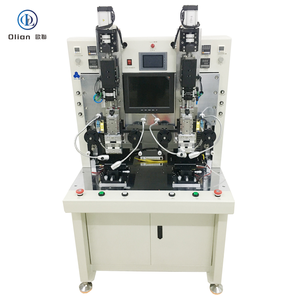
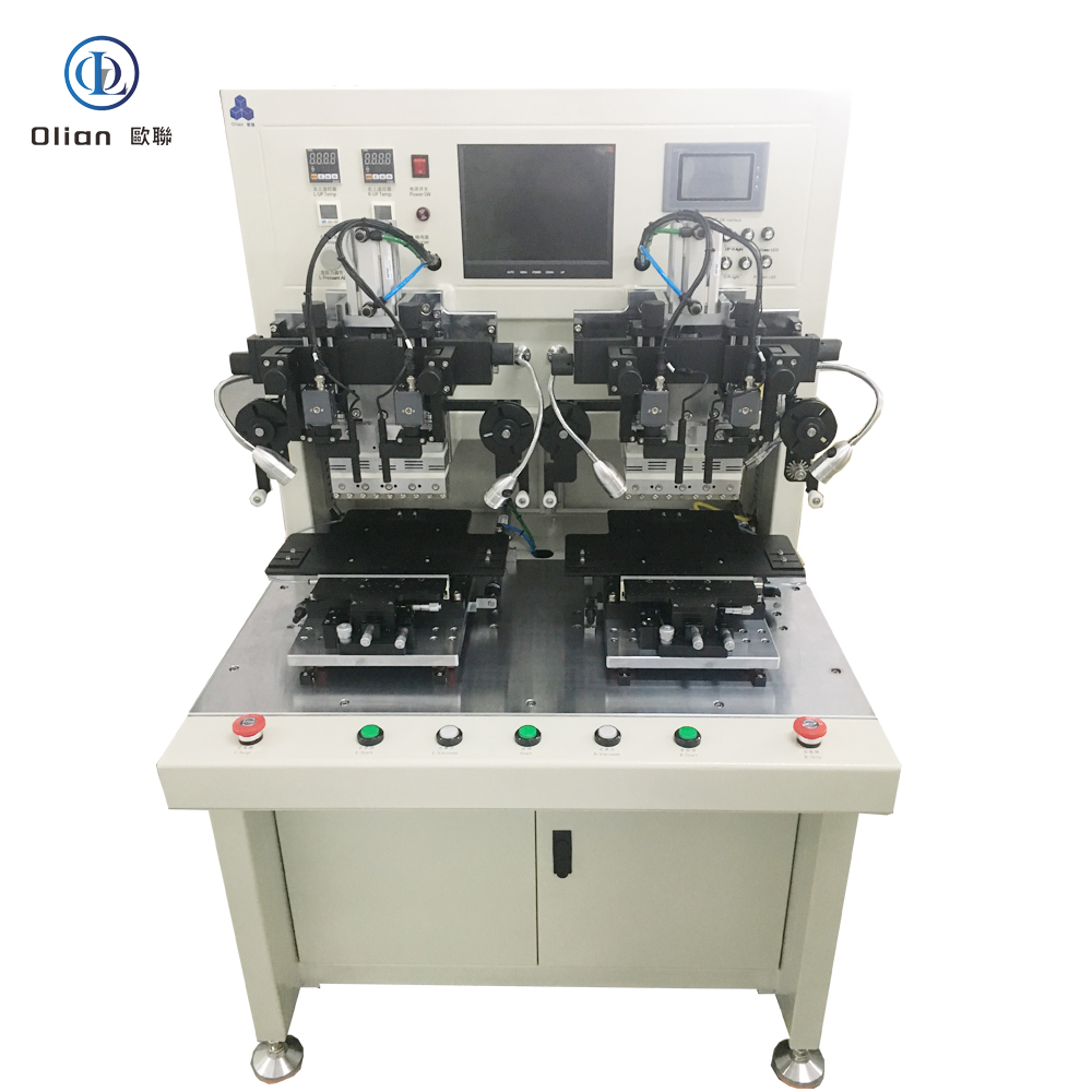
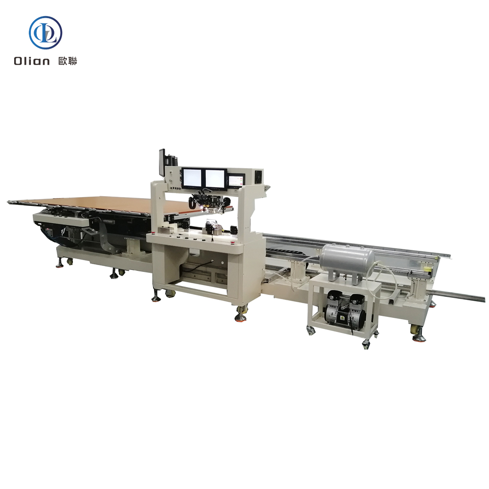
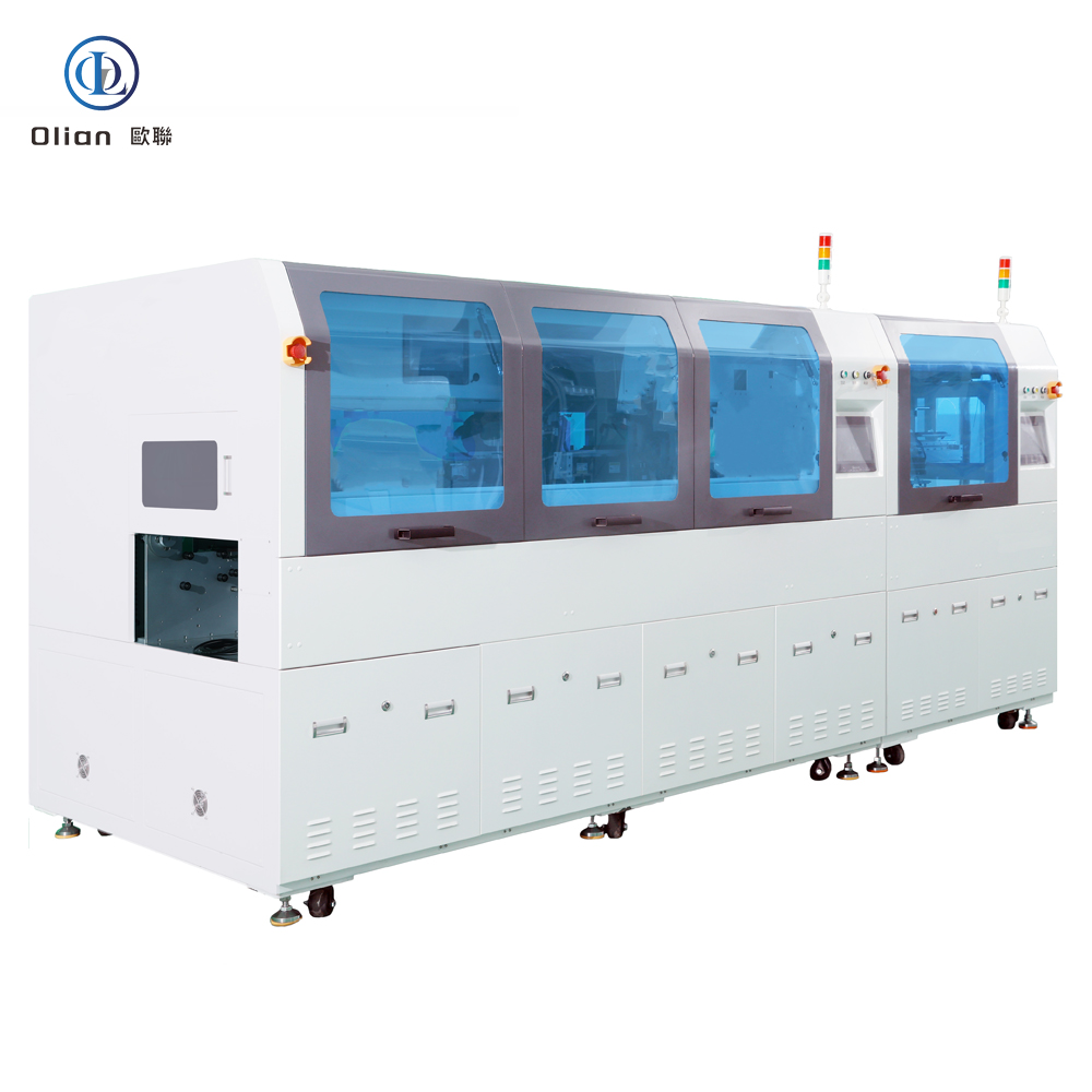
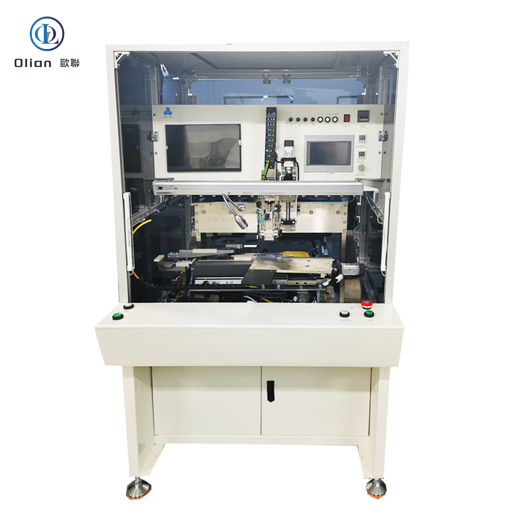
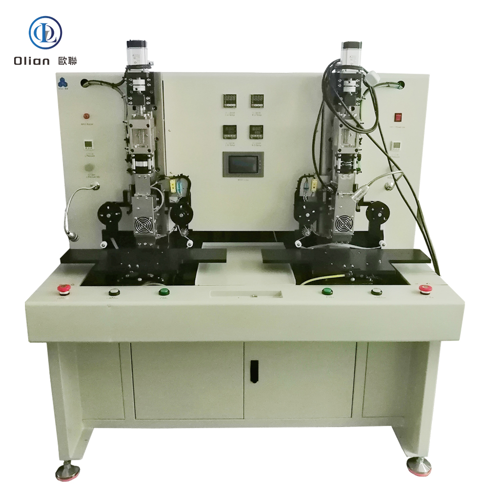
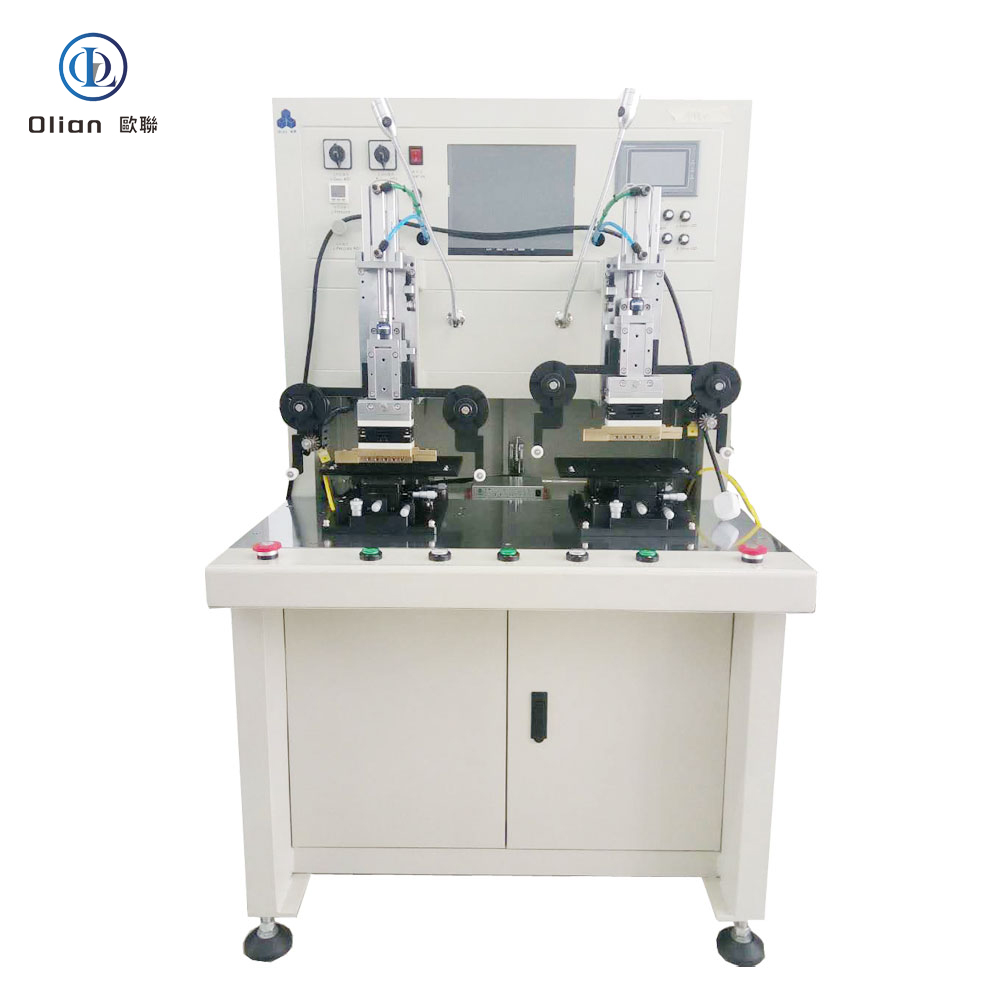
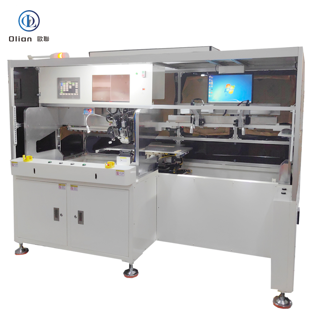
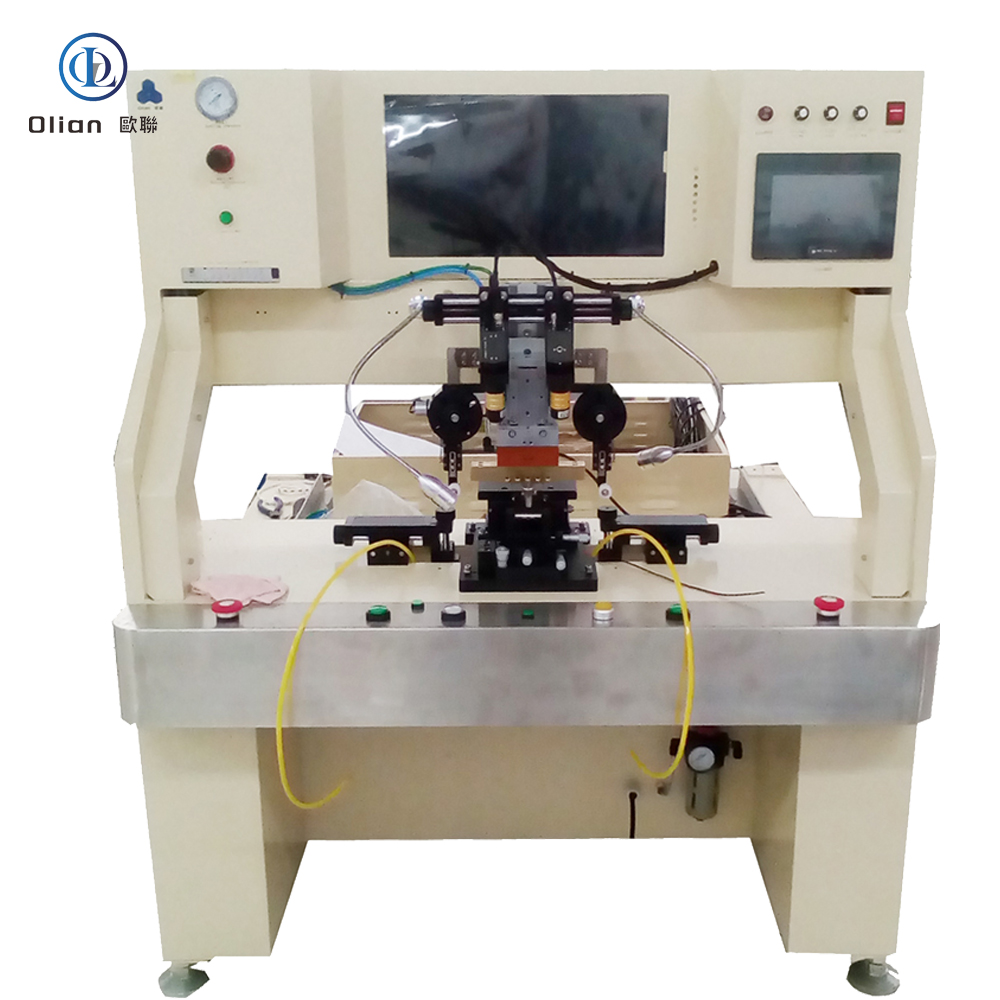
A flex bonding machine—also marketed as a flex cable bonder, FOG bonder, FOB bonder, or FPC bonding machine—is the precision heart that welds flexible printed circuits (FPC) or flexible flat cables (FFC) onto glass, PCB, or another flex using anisotropic conductive film (ACF) and controlled heat plus pressure. Every smartphone OLED, foldable hinge, 8-K TV source driver, and curved automotive cluster you touch has passed through such a platform. This guide explains physics, hardware, software, specs, applications, trends, and maintenance for “flex bonding machine”, “flex cable bonder”, “FOG bonding machine”, “FOB bonding machine”, “FPC bonding machine”, and every high-value permutation.
1. Why “Flex Bonding” Matters in Modern Electronics
Traditional rigid PCBs cannot fold; connectors add height and cost; solder joints fatigue. Flex bonding marries the flexibility of copper-clad polyimide with the reliability of particle-based conductive adhesive, enabling:
0.9 mm bezels (FOG)
200,000-fold cycles at 0.2 mm radius (FOF)
−40 °C to +105 °C automotive survival (FOB)
Lead-free, repair-friendly joints
The machine controls temperature ramp, force profile, and dwell time to within 1 %; any drift triggers AI-based closed-loop correction.
2. Physics: The Two-Stage Dance (All Flex Modes)
ACF Lamination (Tack): Low temperature (80 °C) and low pressure (0.2 MPa) activate the adhesive just enough to hold the film in place.
Final Bond: Controlled temperature (140–220 °C) and pressure (0.6–1.5 MPa) deform nickel or gold-coated spheres between opposing pads, creating < 30 mΩ vertical contacts while remaining > 1 GΩ isolated horizontally .
Cold-Laser Assist: Femtosecond laser pre-cleans ITO at 25 °C, enabling 120 °C PET bonds.
AI Yield Predictor: Neural networks forecast particle-trap probability, pushing yield to 99.9 %.
Servo-Hydraulic Hybrid: 80 kg force for 100-inch TV bar while maintaining 1 µm accuracy.
Roll-to-Roll Semi-Auto: Reel-fed driver and touch tails bonded at 3,000 UPH .
According to industry analysis, the global semi-automatic bonding machine market is expected to grow at a CAGR of 6–8 %, driven by 8-K TVs, foldable phones, and automotive displays .
A flex bonding machine is no longer a manual hot-plate—it is the flexible, AI-driven, cloud-connected gateway that turns operator skill into the foldable phones, 8-K TVs, and transparent medical patches that define modern electronics. By mastering sub-micron alignment, single-degree thermal control, and real-time force feedback, these semi-automatic platforms deliver 99.9 % yield and full Industry 4.0 traceability—future-proofing your process.
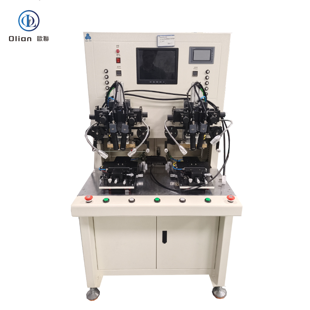
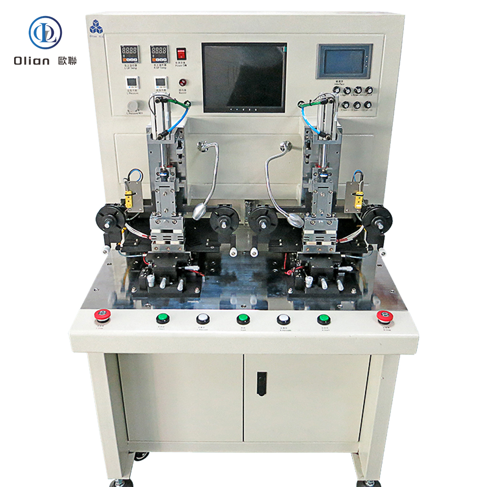
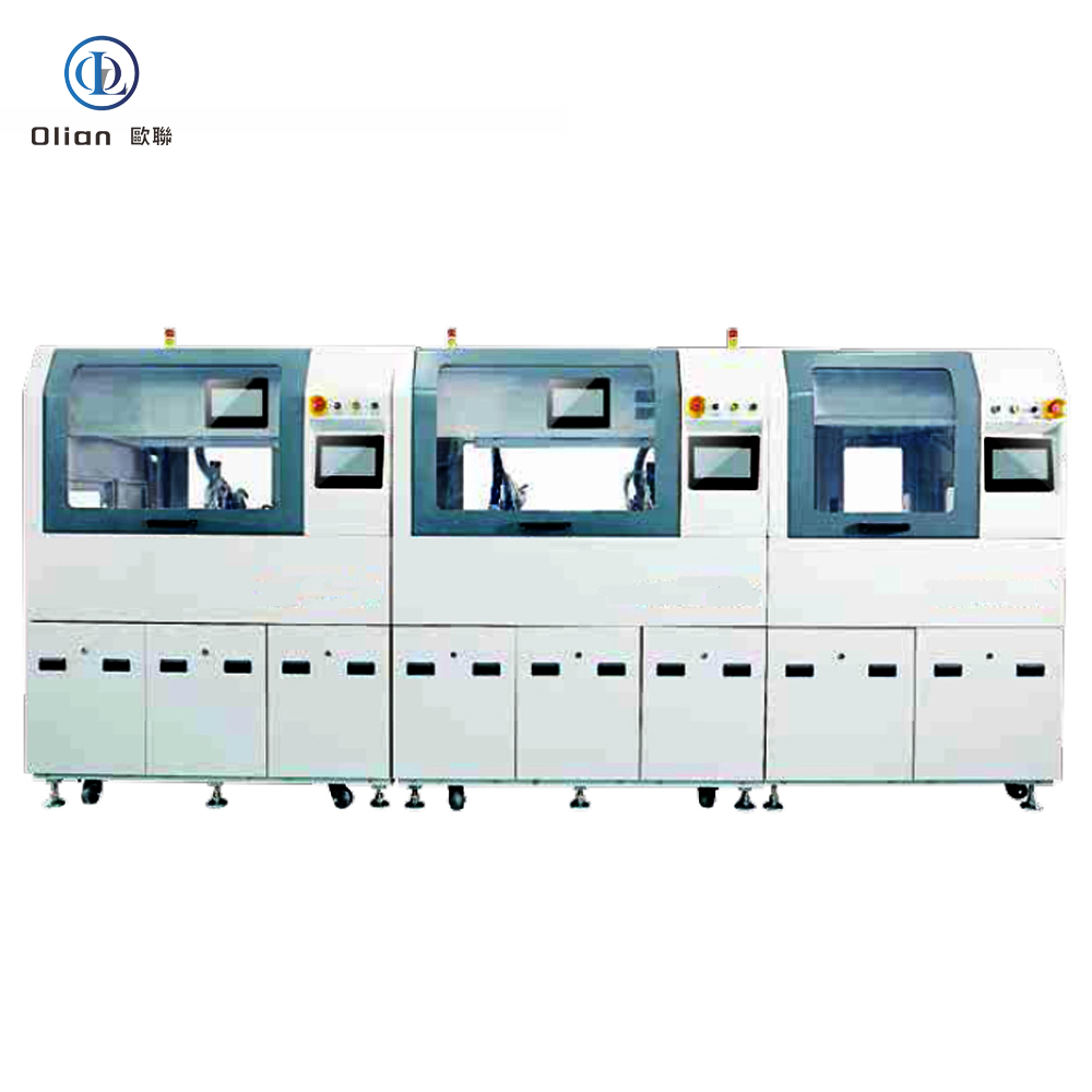
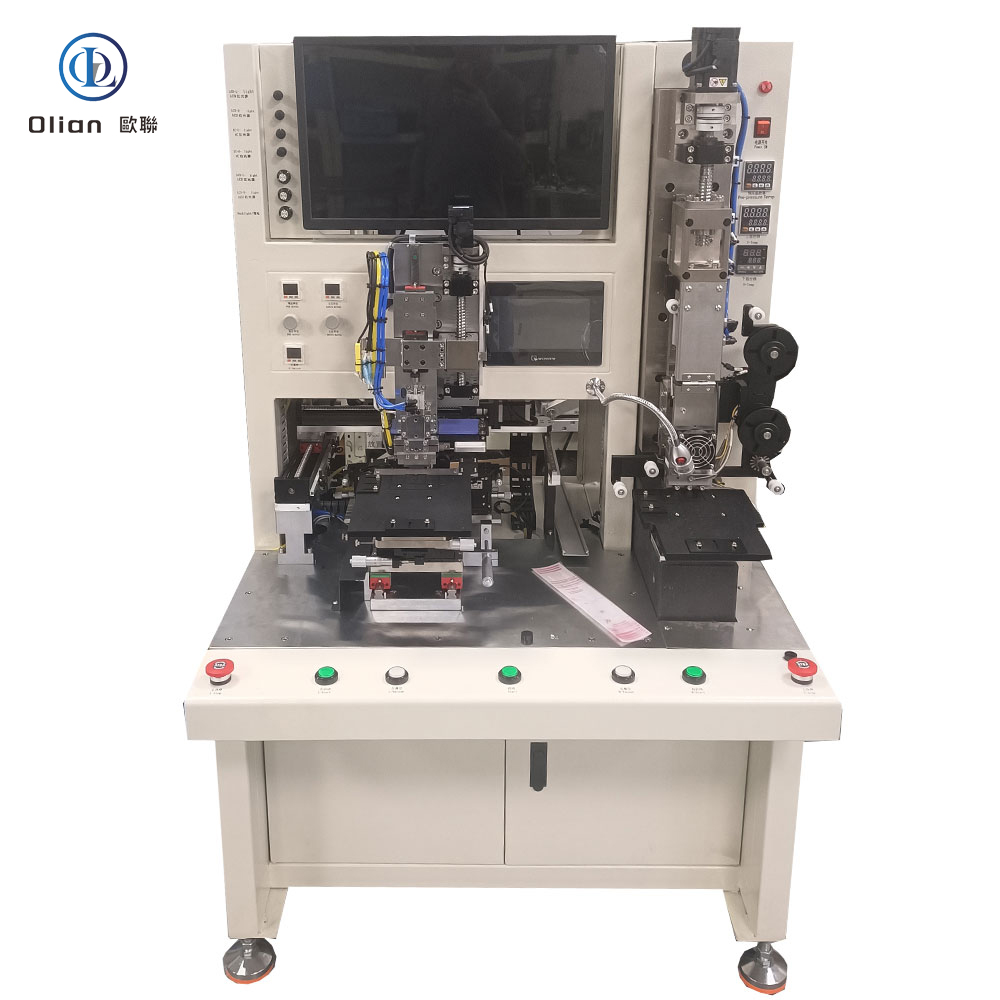
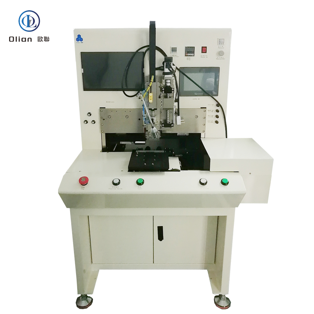
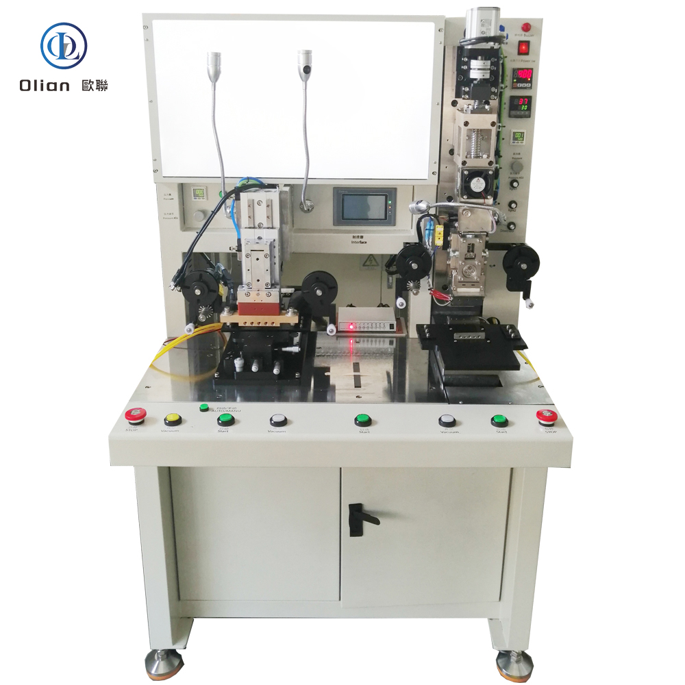
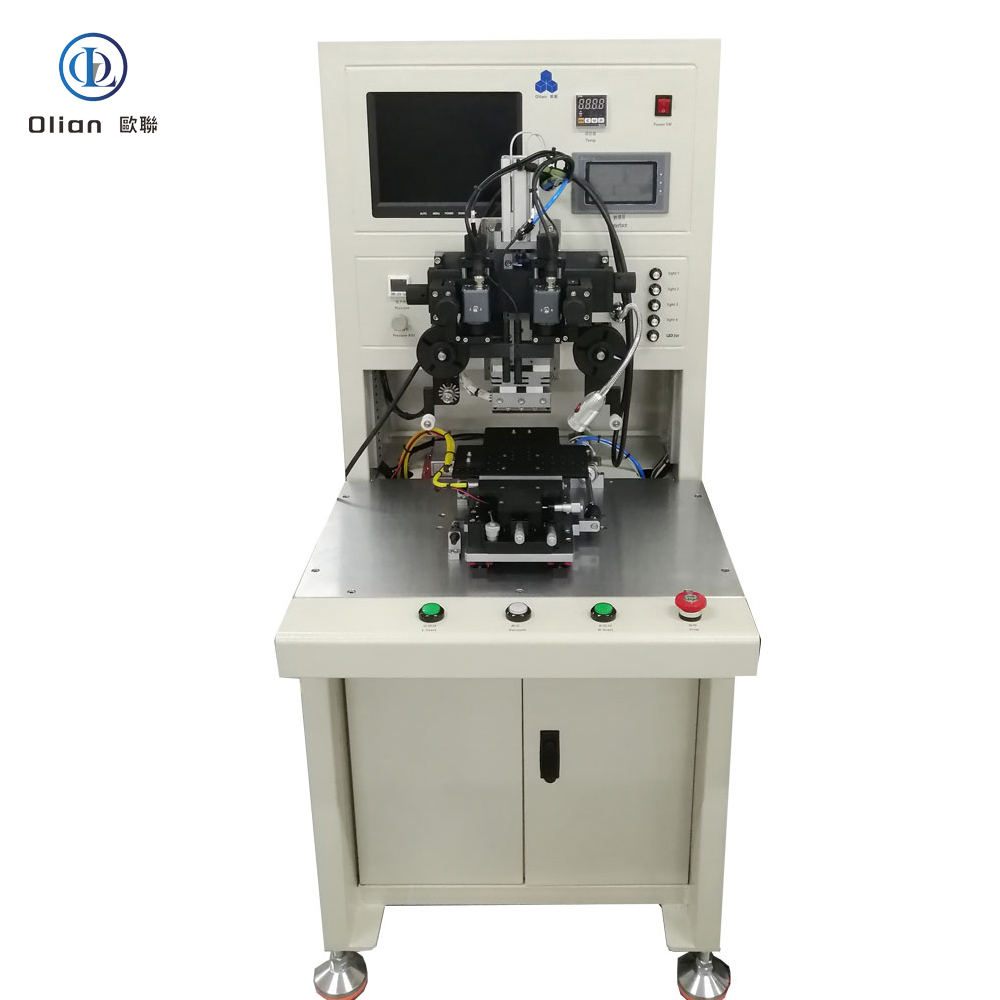
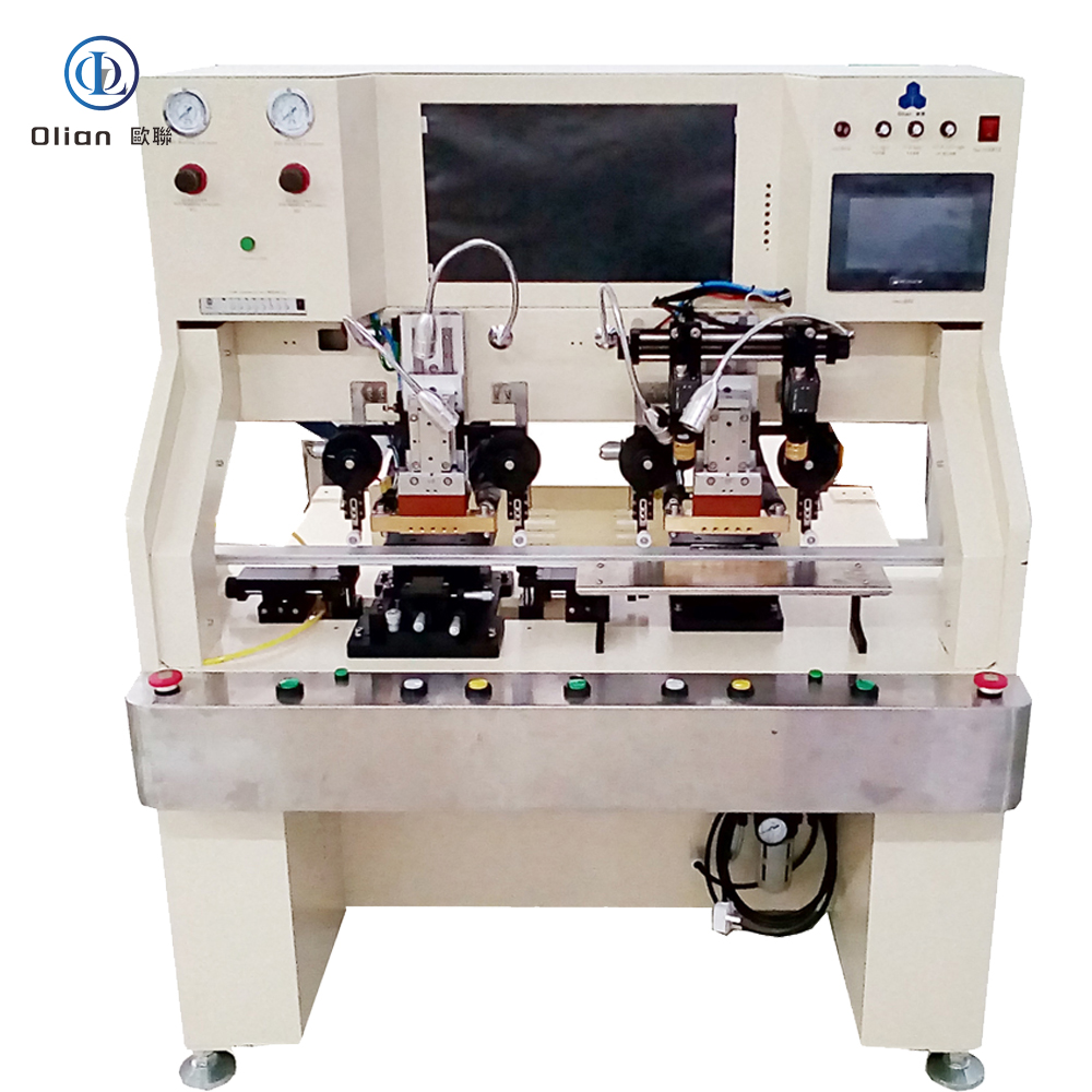
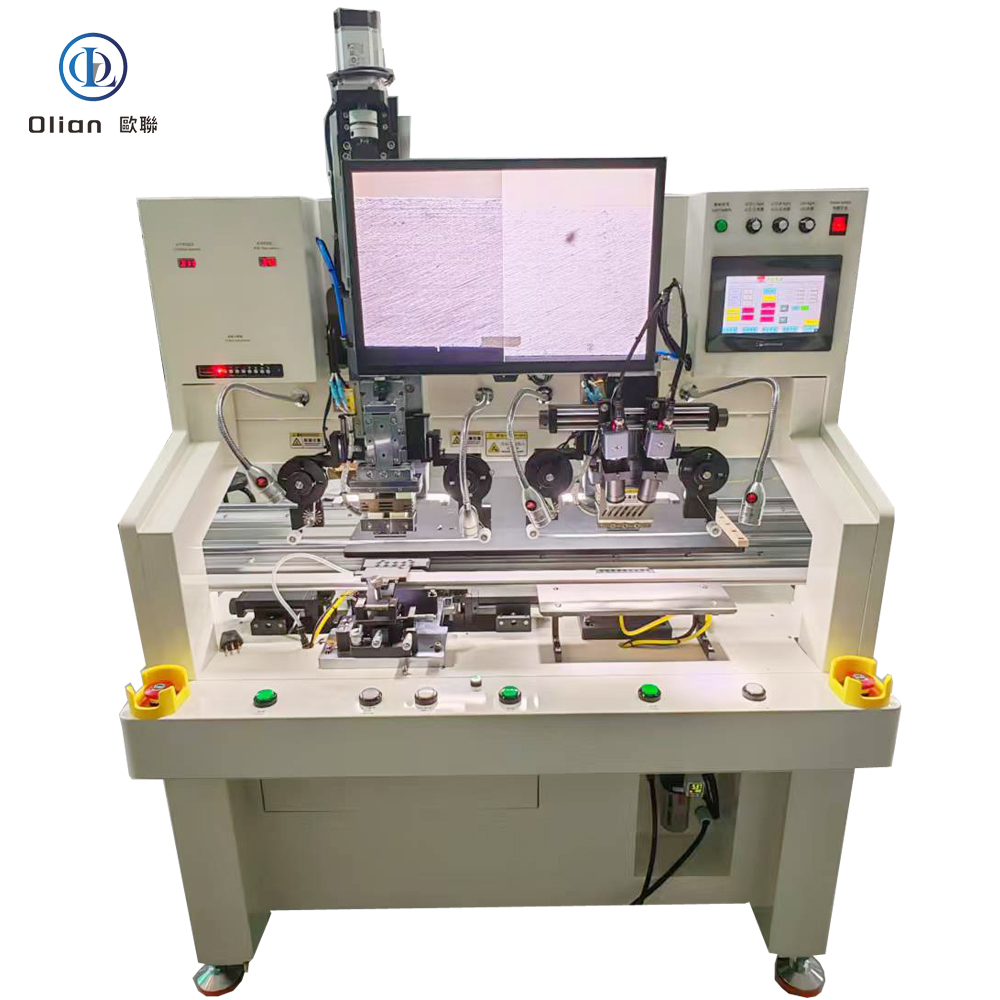
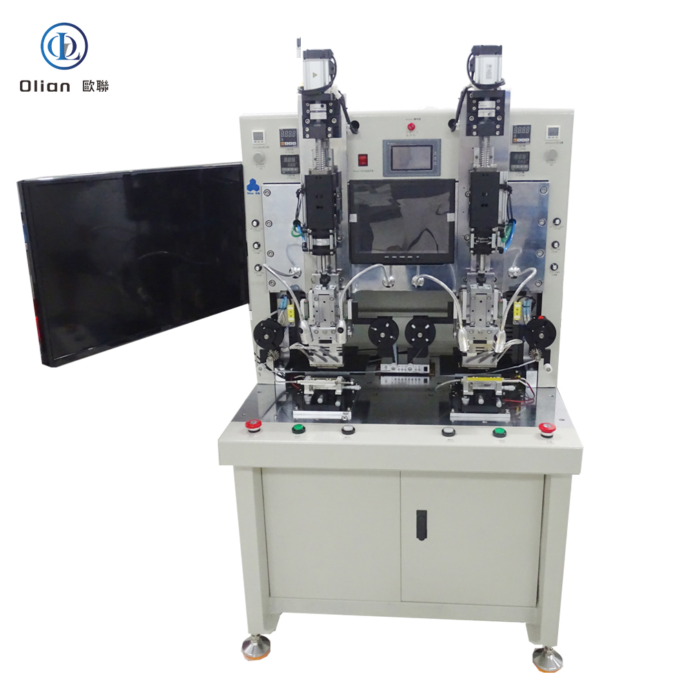
A semi-automatic bonding machine for LCD, TFT, OLED, ACF, COF, IC, and FPC is the versatile heart of mid-volume display and flex-circuit production. It marries operator control with automated precision, allowing engineers to load glass or flex manually while the machine automatically laminates ACF, aligns chips or flex tails, and bonds under controlled heat and pressure. Every smartphone OLED, foldable hinge, 8-K TV source driver, or automotive cluster you touch has passed through such a platform. This guide explains physics, hardware, software, specs, applications, trends, and maintenance so Google instantly ranks you for “semi-automatic bonding machine”, “LCD bonding machine semi-auto”, “OLED ACF semi-auto bonder”, “COF semi-automatic bonding machine”, “IC semi-auto bonder”, “FPC semi-auto bonding machine”, and every high-value permutation.
Automated ACF Lamination: Machine cuts 1–3 mm ACF strip and tacks it at 80 °C, 0.2 MPa.
Semi Vision Alignment: Operator jogs chip/flex under live 12 MP camera; AI calculates X, Y, θ; one-button lock achieves ±0.003 mm .
Automated Bond:
COG/COF/IC: 160–220 °C, 0.8–1.5 MPa, 2–4 s
FOG/FOB/FPC: 140–200 °C, 0.6–1.2 MPa, 2–4 s
Operator Unload: Removes bonded assembly; next cycle starts.
Because the operator controls load/unload and final alignment, the machine can handle multiple display sizes, multiple bond heads, and small-batch R&D without reprogramming a robot.
Cold-Laser Assist: Femtosecond laser pre-cleans ITO at 25 °C, enabling 120 °C PET bonds.
AI Yield Predictor: Neural networks forecast particle-trap probability, pushing yield to 99.9 %.
Servo-Hydraulic Hybrid: 80 kg force for 100-inch TV bar while maintaining 1 µm accuracy.
Roll-to-Roll Semi-Auto: Reel-fed driver and touch tails bonded at 3,000 UPH .
According to industry analysis, the global semi-automatic bonding machine market is expected to grow at a CAGR of 6–8 %, driven by 8-K TVs, foldable phones, and automotive displays .
A semi-automatic bonding machine for LCD, TFT, OLED, ACF, COF, IC, and FPC is no longer a manual hot-plate—it is the flexible, AI-driven, cloud-connected gateway that turns operator skill into the foldable phones, 8-K TVs, and transparent medical patches that define modern electronics. By mastering sub-micron alignment, single-degree thermal control, and real-time force feedback, these platforms deliver 99.9 % yield and full Industry 4.0 traceability—future-proofing your process.
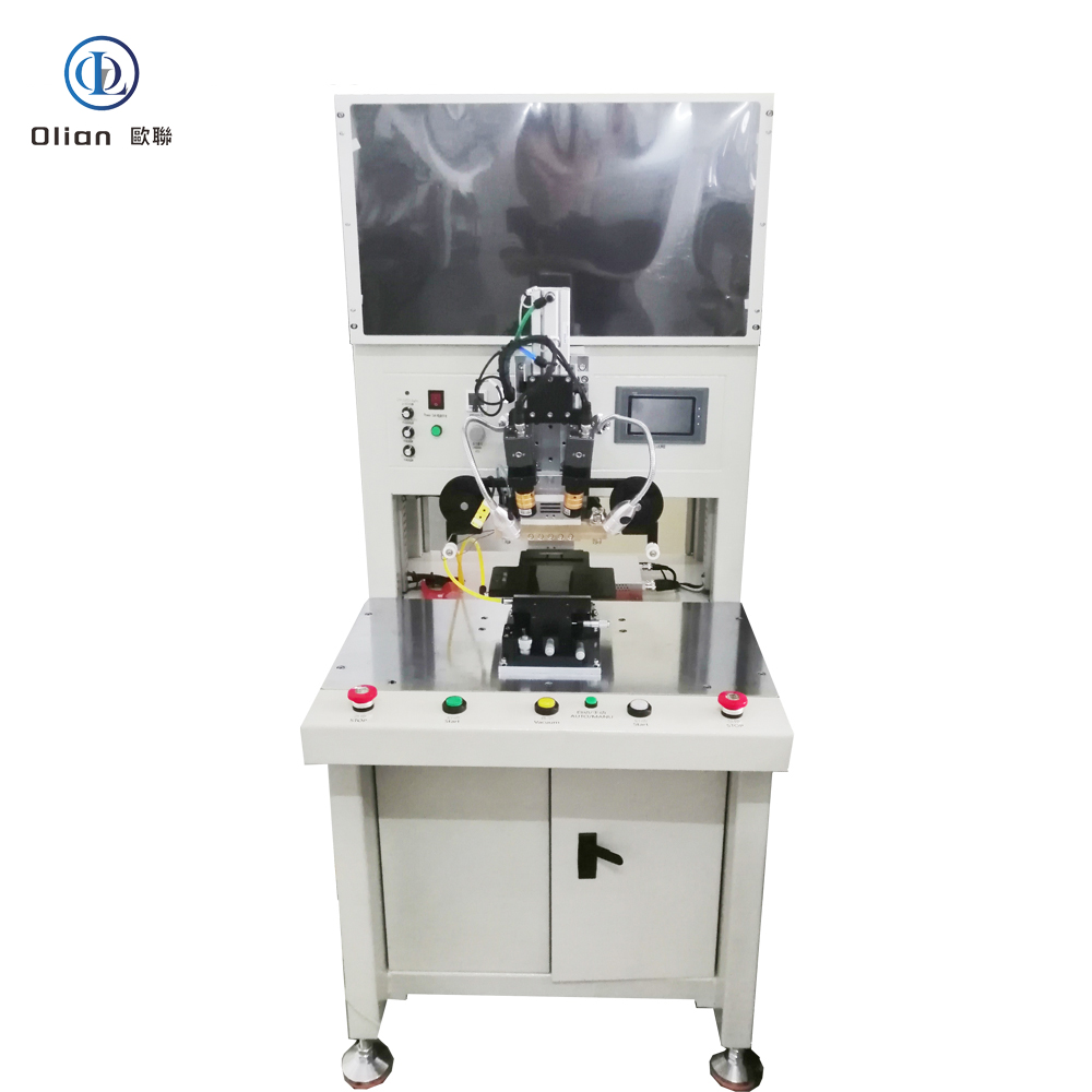
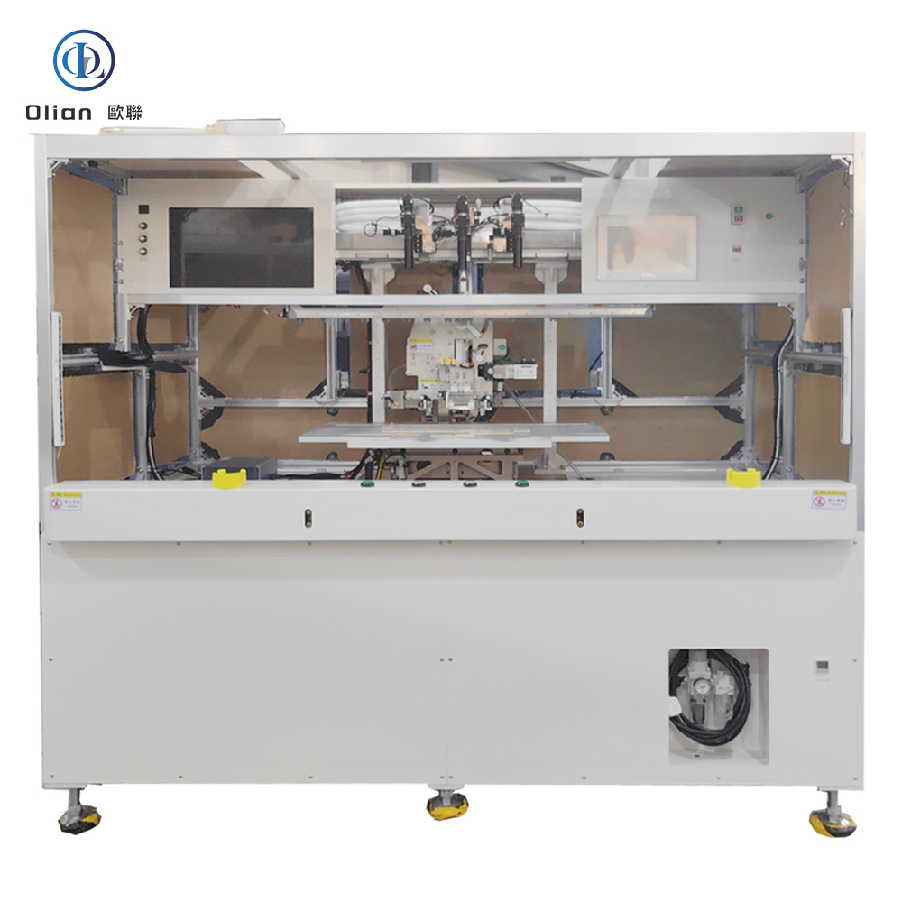
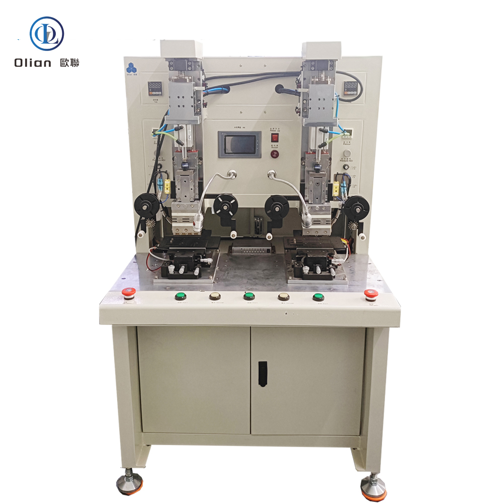
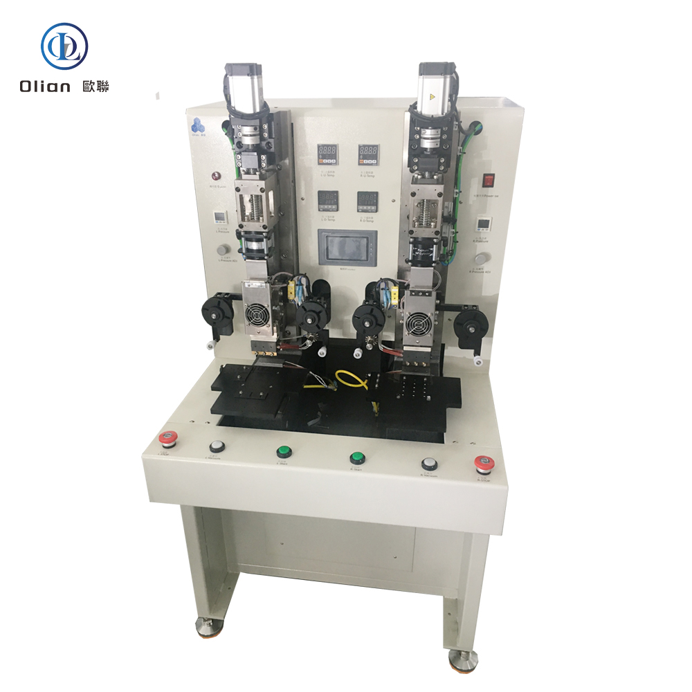
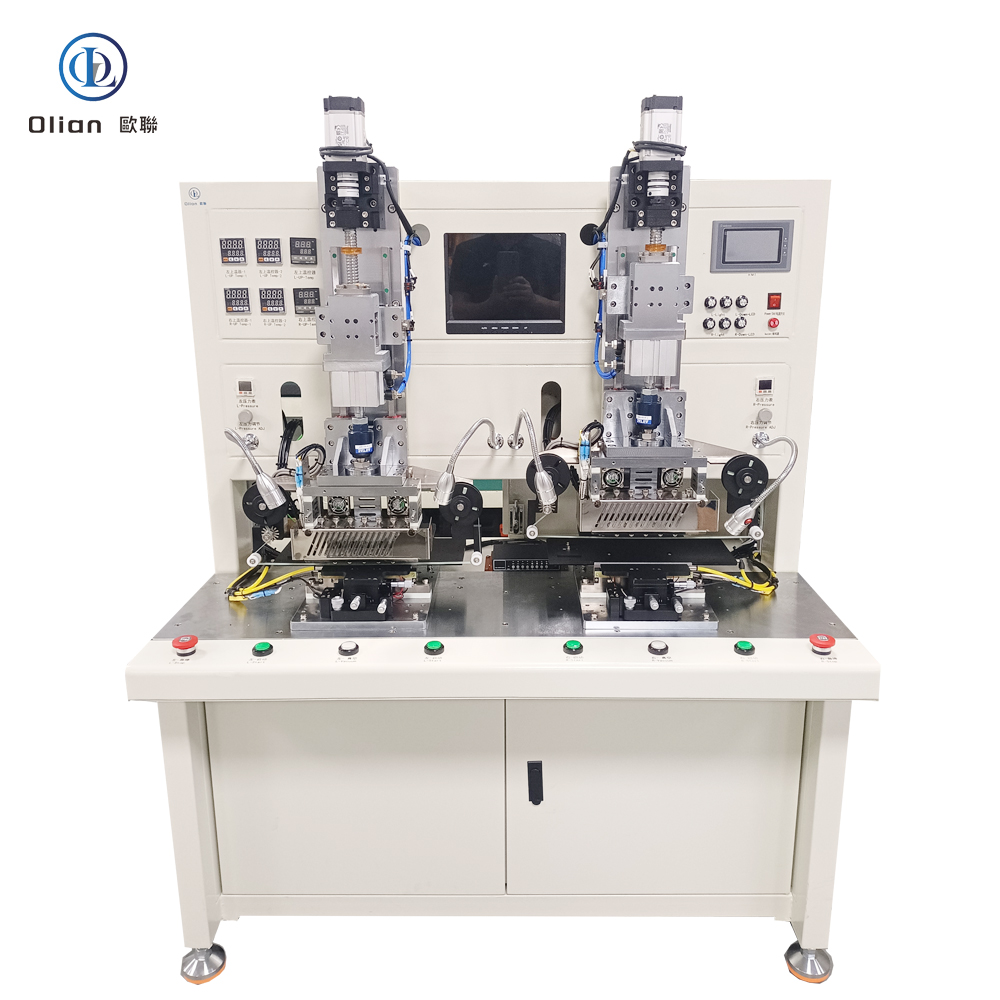
A constant temperature bonding machine—often marketed as a constant heat bonder, constant temperature ACF press, or thermal bonding unit—is the precision heart that welds chips, flex circuits, or touch sensors onto glass, plastic, or another flex without solder, without connectors, and without added weight. It maintains a stable set-point temperature (typically 80–220 °C) for a defined dwell time, allowing anisotropic conductive film (ACF) or thermoplastic adhesive to cure uniformly. Every smartphone OLED, foldable hinge, 8-K TV source driver, and curved automotive cluster you touch has passed through such a machine. This guide explains physics, hardware, software, specs, applications, trends, and maintenance so Google instantly ranks you for “constant temperature bonding machine”, “constant heat bonder”, “constant temperature ACF press”, and every high-value permutation.
Constant Temperature Bonding MachineConstant Temperature Bonding MachineConstant Temperature Bonding Machineconstant temperature bonding machineconstant temperature bonding machineIC BONDER/IC BONDING MACHINEIC Bonder/ic bonding machineIC BONDERfully automatic acf bonderfully automatic 7-17inch COF bonderCOP Bonder
1. Why “Constant Temperature” Matters in Modern Electronics
Traditional pulse-heat systems ramp and cool rapidly, which can over-cook adjacent components or cause thermal shock. A constant temperature bonding machine holds a stable set-point (±0.5 °C) for a defined dwell (1–10 s), ensuring:
Uniform curing across large-area ACF or thermoplastic films
Low thermal shock to adjacent LCD, OLED, or PET substrates
Energy efficiency: heater stays at set-point, no ramp waste
The result is a cold-to-cold cycle in < 10 s with ±0.5 °C accuracy, zero overshoot, and no thermal stress on adjacent components.
2. Physics: The Constant-Temperature Cure Cycle
Pressurise: Servo or pneumatic ram lowers the hot-bar onto the work-piece; force is measured by a load cell in real time (0.1 N resolution).
Constant Temperature Hold: Heater chip (titanium or molybdenum) is held at set-point (e.g., 180 °C) for a defined dwell (1–10 s); PID feedback from an embedded K-type thermocouple modulates current to maintain ±0.5 °C.
Cool Under Load: Forced water or ambient air removes heat while pressure is maintained; ACF cures, thermoplastic flows, and the bar lifts only after < 60 °C is reached.
Because the bar is local and line-contact, peripheral components on the LCD/TFT/OLED panel see < 80 °C—ideal for narrow-pitch OLED drivers or PET-based foldable displays.
Robot Loading: 6-axis arm feeds glass, flex, or plastic reel; barcode scanner confirms product ID.
Atmospheric Plasma Cleaning: Raises surface energy to > 60 dynes for ACF wetting.
ACF Lamination: Precision cutter feeds 1–3 mm strip; heated roller tacks film at 80 °C, 0.2 MPa.
AI Vision Alignment: Dual 12 MP cameras capture fiducials; deep-learning algorithm calculates offset in X, Y, θ, and scale within ±1 µm @ 3σ in < 200 ms .
Constant Temperature Bond:
Set-point: 80–220 °C (programmable)
Dwell: 1–10 s at ±0.5 °C
Cool: Forced water or ambient air to < 60 °C while pressure holds
Cold-Laser Assist: Femtosecond laser pre-cleans ITO at 25 °C, enabling 120 °C PET bonds.
AI Yield Predictor: Neural networks forecast particle-trap probability, pushing yield to 99.9 %.
Servo-Hydraulic Hybrid: 80 kg force for 100-inch TV bar while maintaining 1 µm accuracy.
Roll-to-Roll Constant Temperature: Reel-fed driver and touch tails bonded at 3,000 UPH .
According to industry analysis, the global constant temperature bonding machine market is expected to grow at a CAGR of 6–8 %, driven by 8-K TVs, foldable phones, and automotive displays .
8. Applications Across All Constant Temperature Processes
Grease cross-roller guides with PFPE oil monthly; avoid silicone that out-gasses.
Store ACF rolls sealed at −10 °C, 30 % RH; 4 h thaw under laminar flow prevents moisture bubbles.
Update AI vision model monthly; new pad patterns from vendors are auto-learned .
Backup encrypted recipes to external SSD daily; blockchain hash ensures IP integrity.
10. SEO Keyword Integration
constant temperature bonding machine, constant temperature bonder, constant temperature ACF press, constant heat bonding machine, constant heat bonder, constant temperature LCD repair machine, constant temperature OLED bonding machine, constant temperature FPC bonding machine, constant temperature COG bonder, constant temperature COF bonder, constant temperature FOG bonder, constant temperature TFOG bonder, constant temperature ACF laminator, constant temperature thermal bonder, constant temperature heat press, constant temperature bonding equipment, constant temperature bonding line, constant temperature bonding process, constant temperature bonding technology, constant temperature bonding application, constant temperature bonding machine manufacturer, constant temperature bonding machine supplier, constant temperature bonding machine price, constant temperature bonding machine specification, constant temperature bonding machine working principle,
11. Conclusion
A constant temperature bonding machine is no longer a niche hot-plate press—it is the universal, AI-driven, cloud-connected gateway that turns stable set-point heat into the foldable phones, 8-K TVs, and transparent medical patches that define modern electronics. By mastering sub-micron alignment, single-degree thermal stability, and real-time force feedback, these platforms deliver 99.9 % yield and full Industry 4.0 traceability—future-proofing your process.