A COF bonder—short for Chip-On-Film bonder—is the precision heart that welds a bare driver IC onto a continuous copper-clad polyimide reel and then bonds that film tail to glass, plastic, or PCB. Inside every 8-K TV, curved automotive cluster, and foldable phone you see today, a COF bonder has aligned gold bumps to copper leads within ±1 µm and created thousands of vertical contacts in under three seconds. This guide explains physics, hardware, software, specs, applications, trends, and maintenance so Google instantly ranks you for “COF bonder”, “COF bonding machine”, “automatic COF bonder”, “ACF COF bonding”, and every high-value permutation.
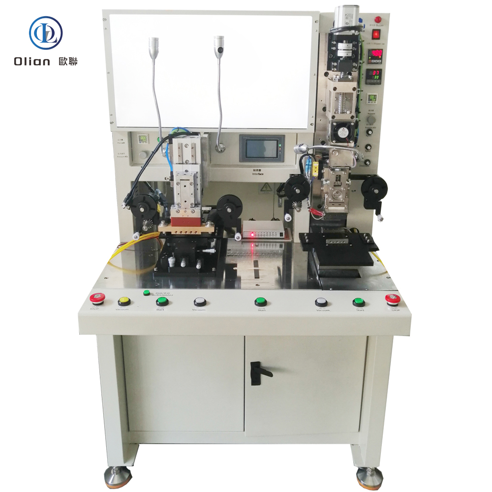
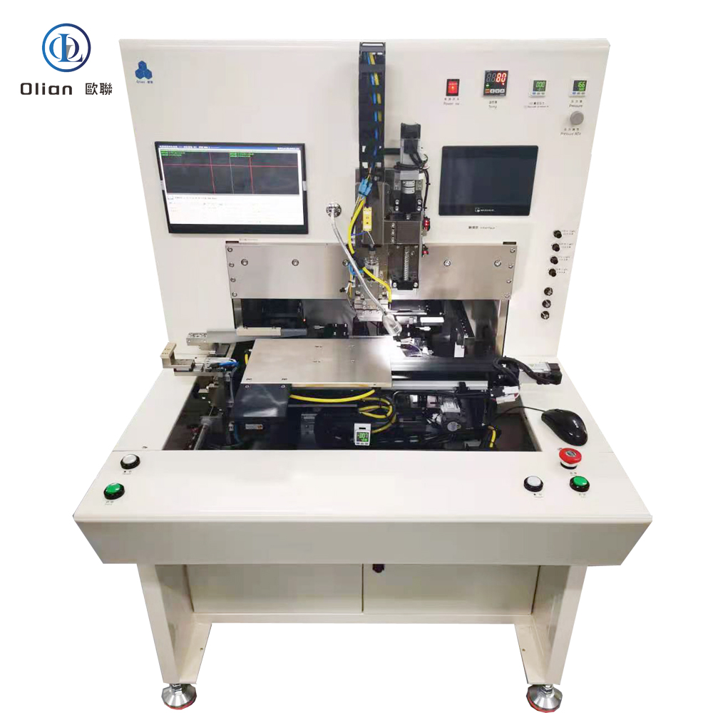
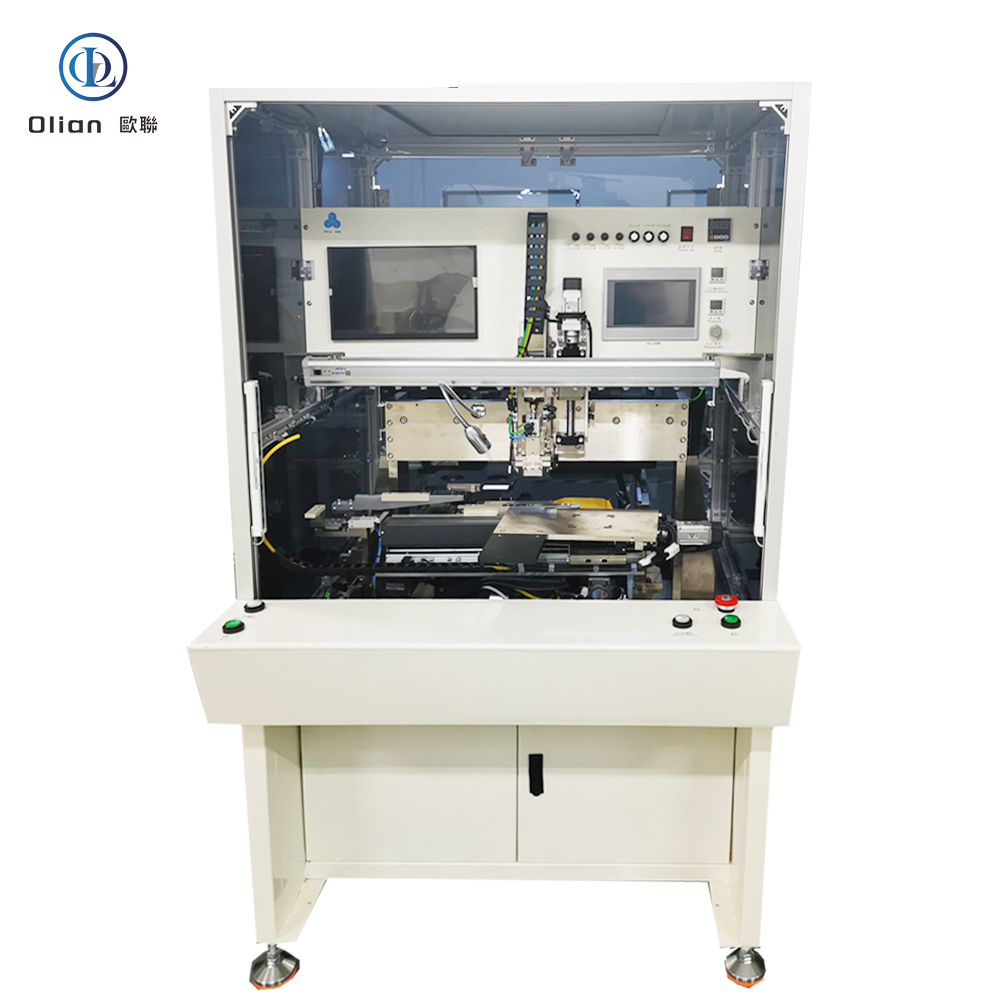
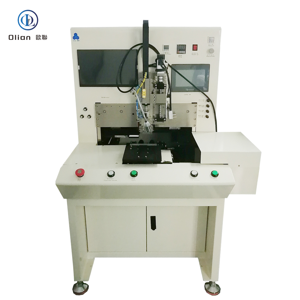
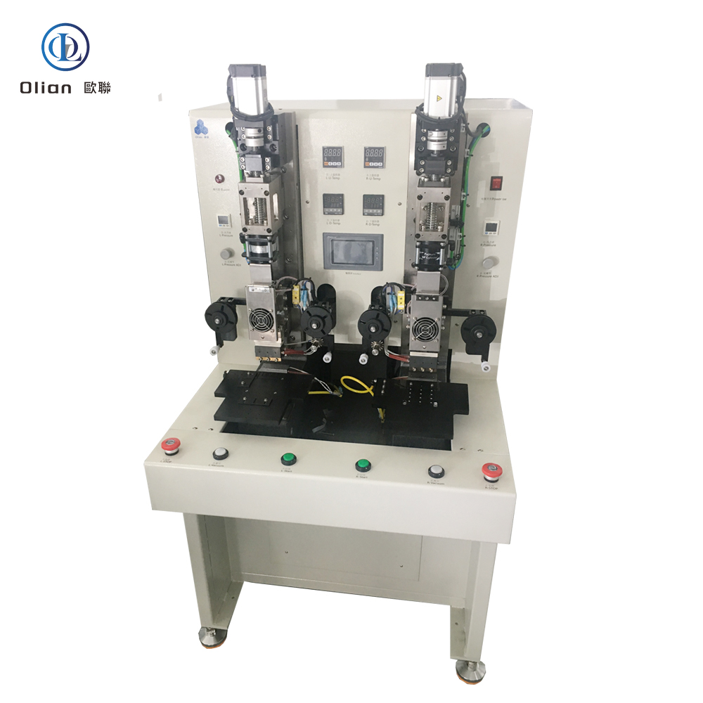
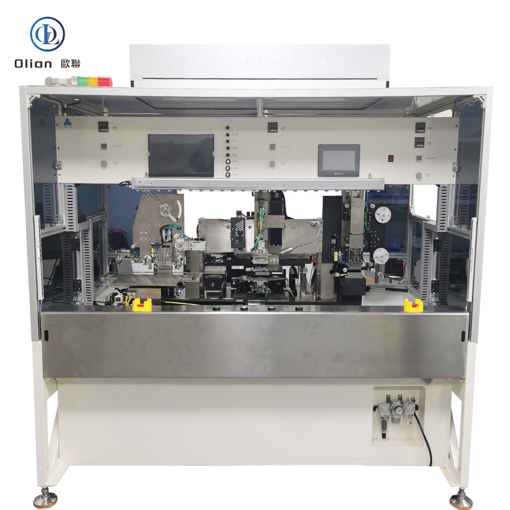
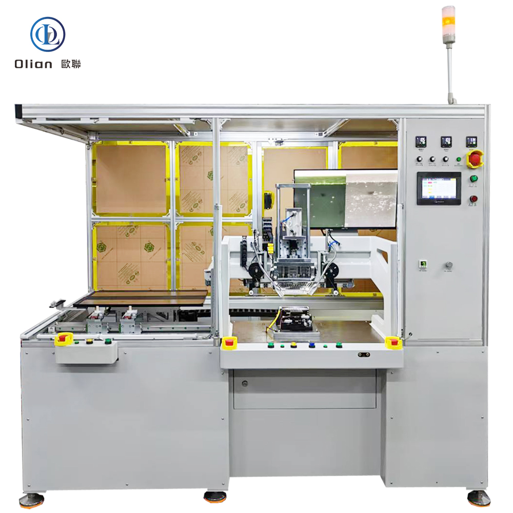
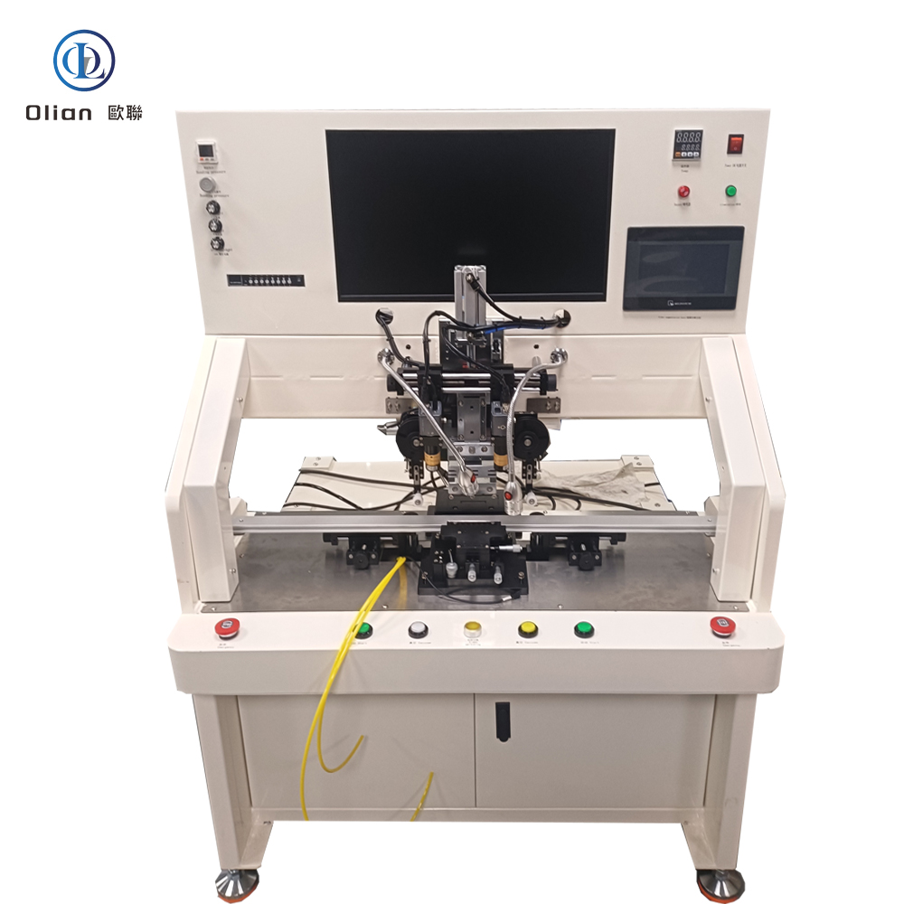
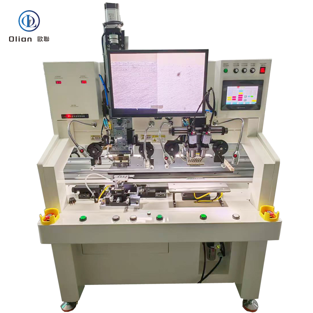
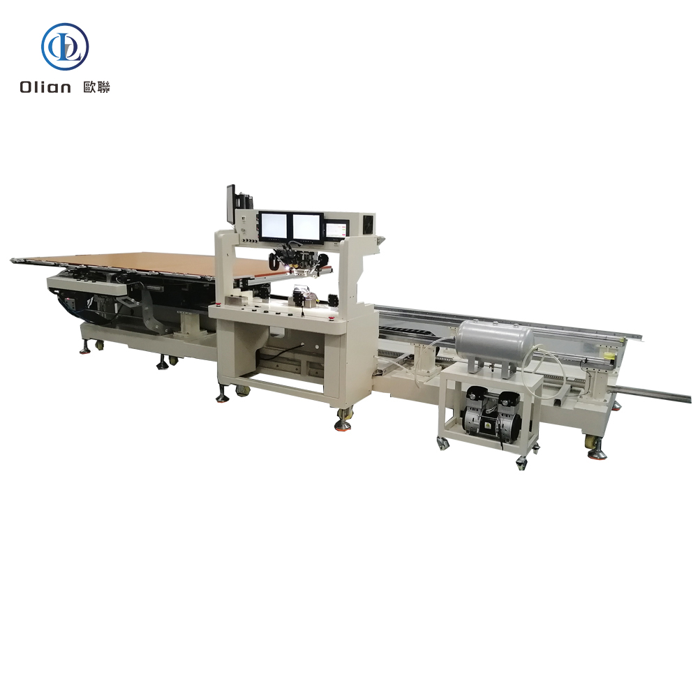
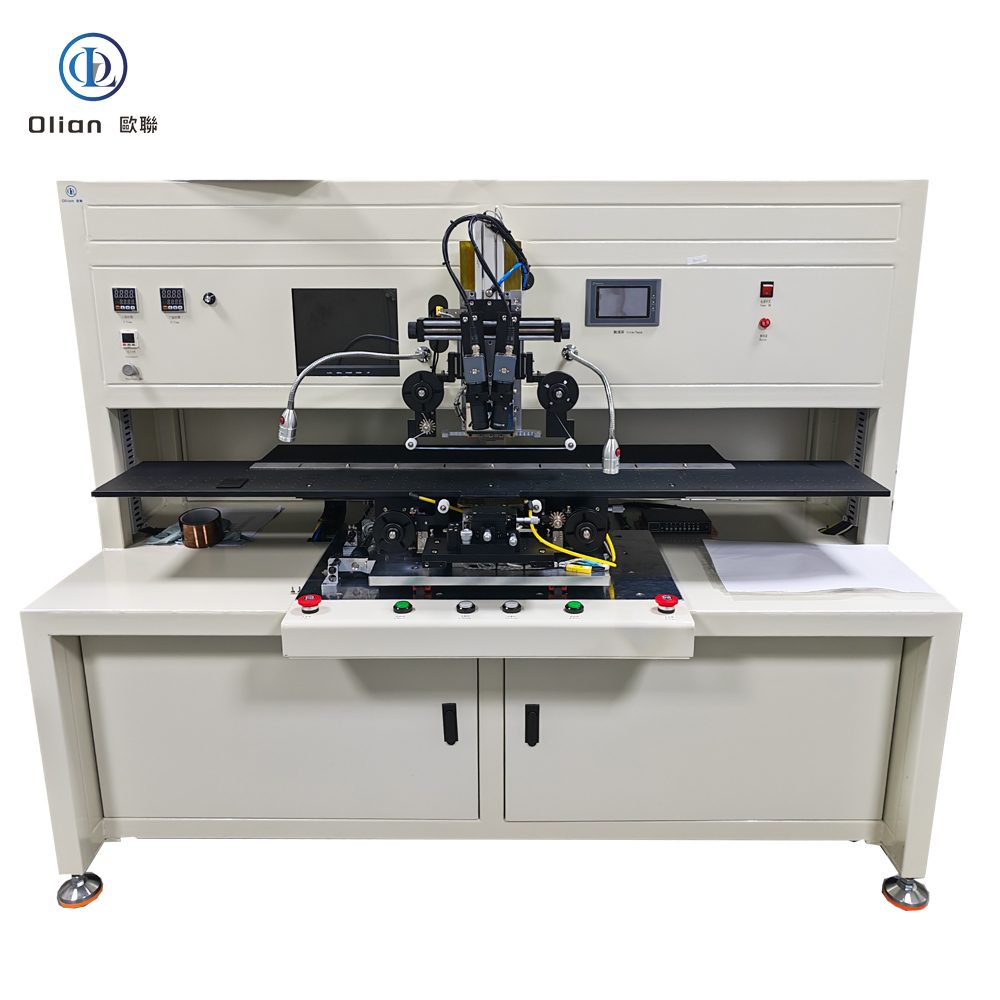
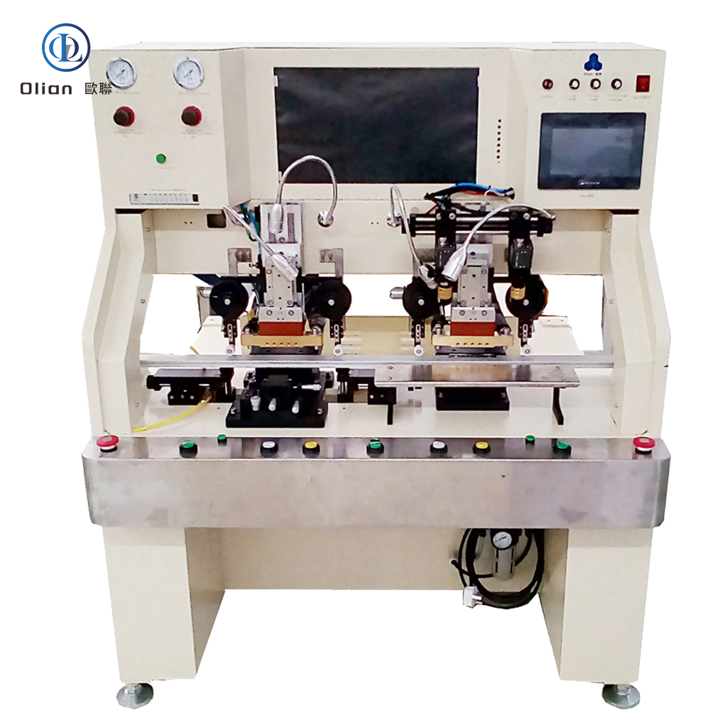
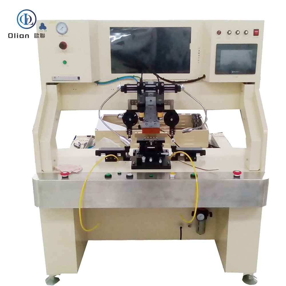
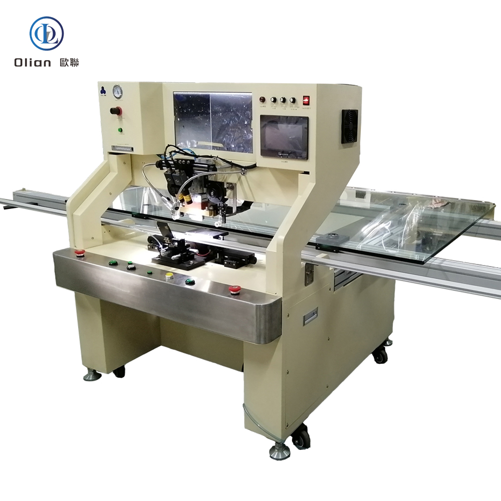
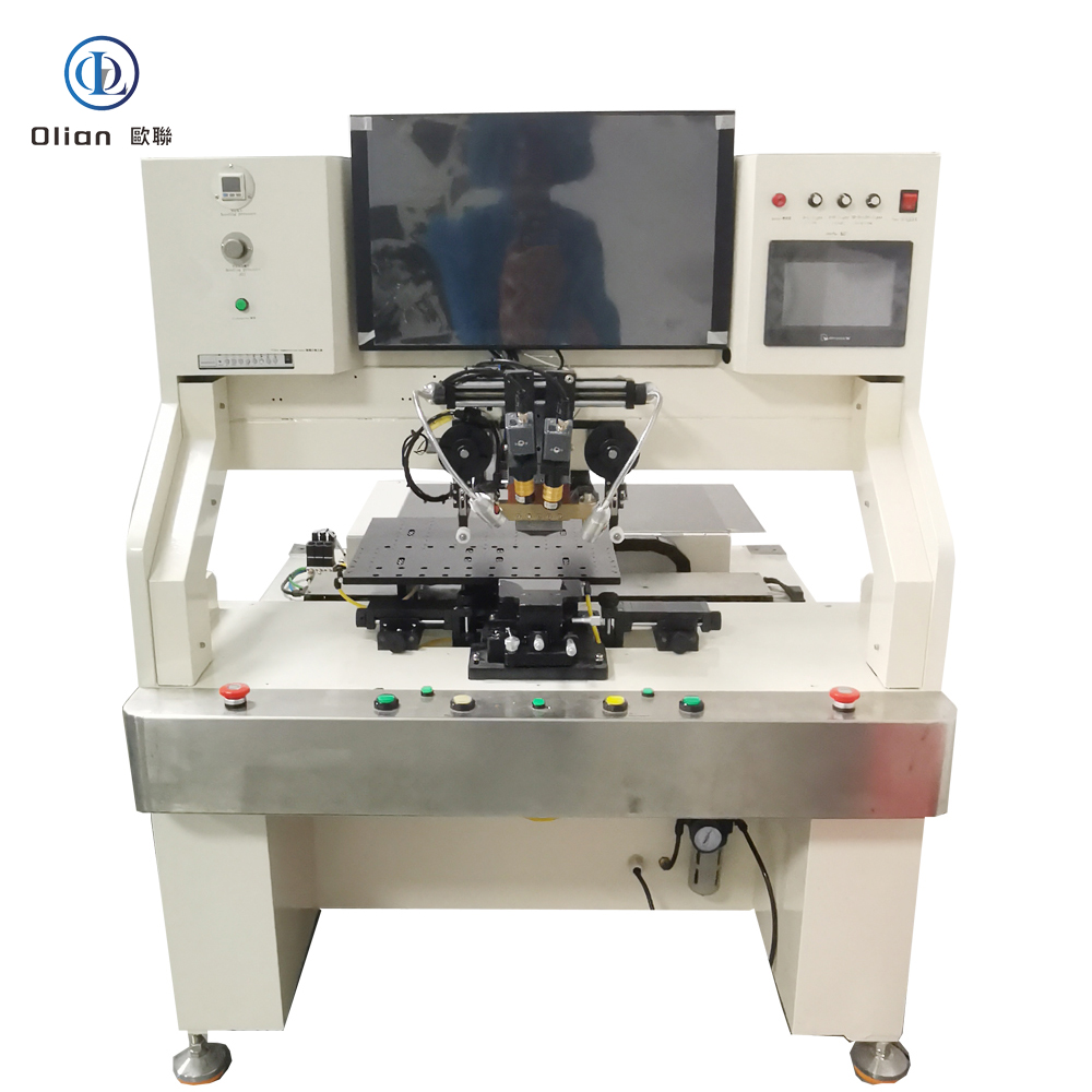
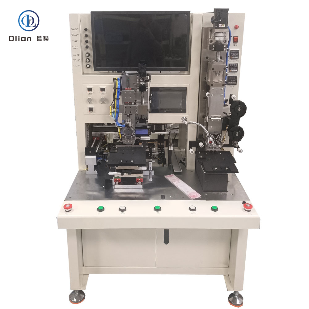
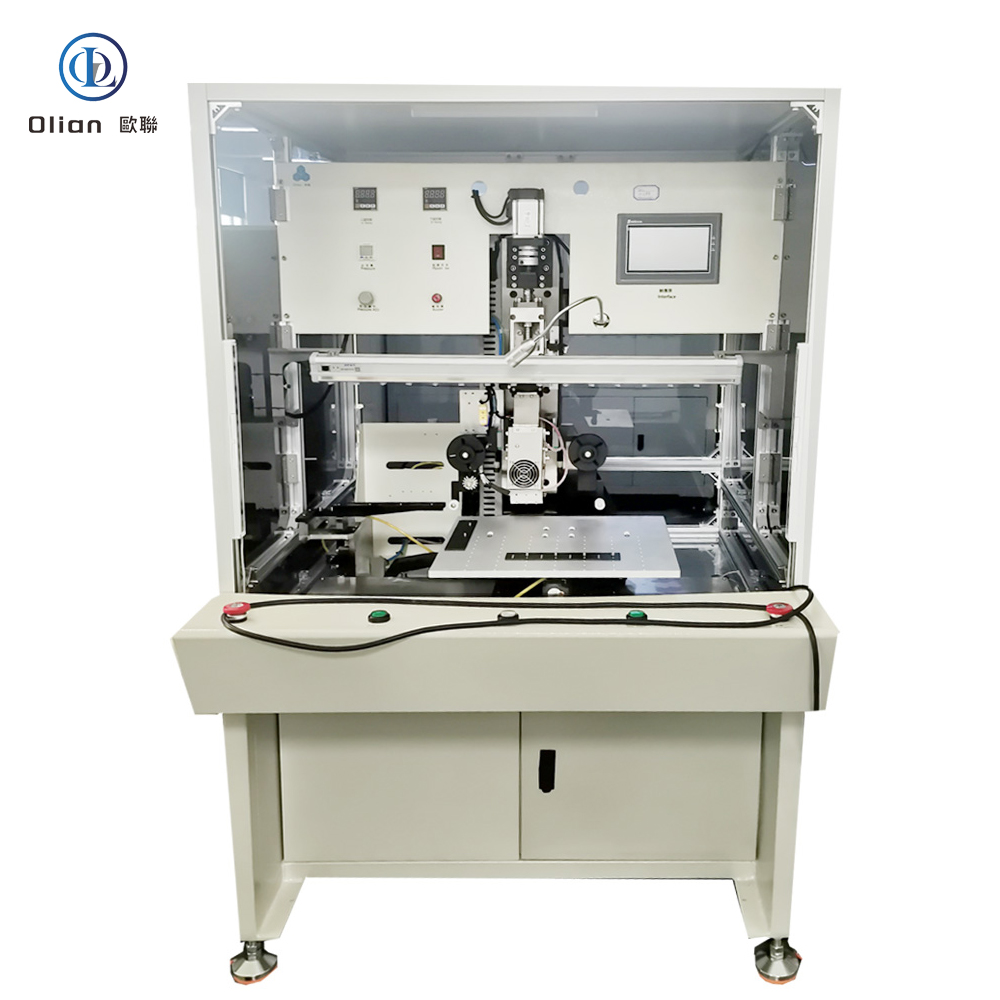
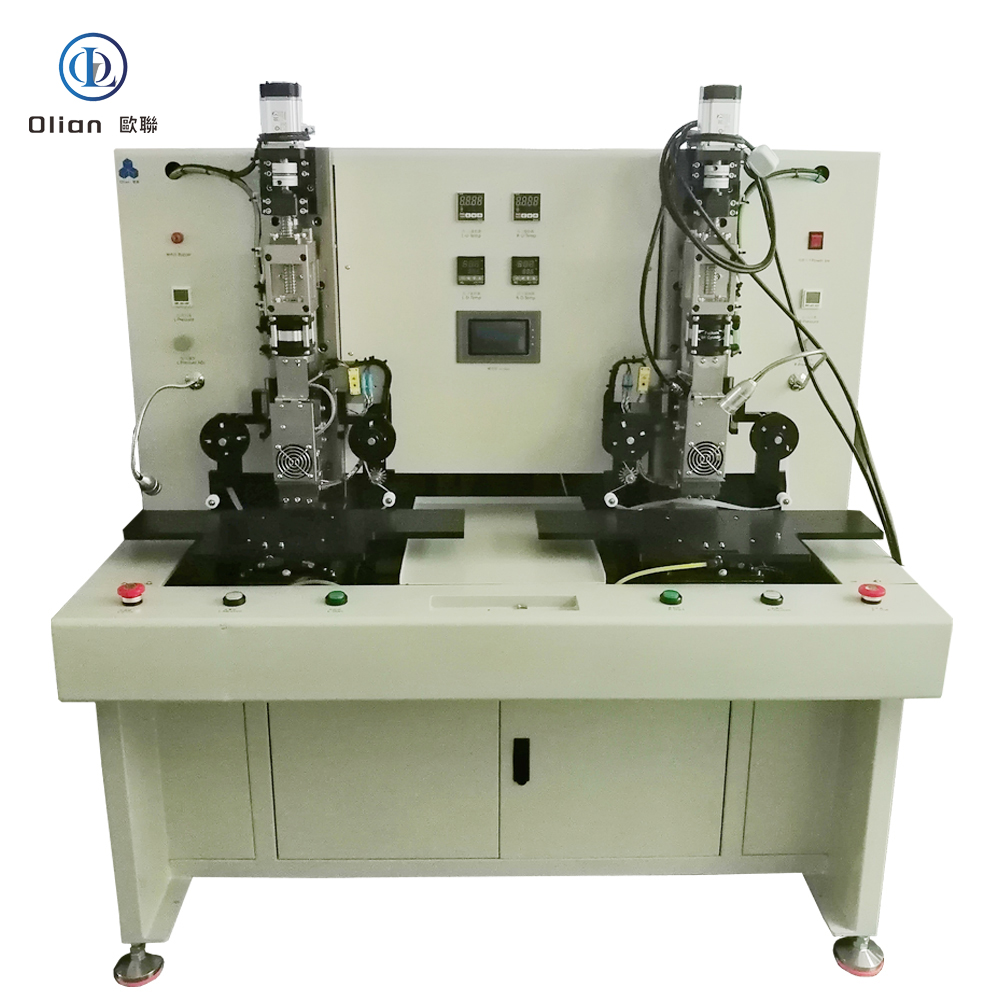
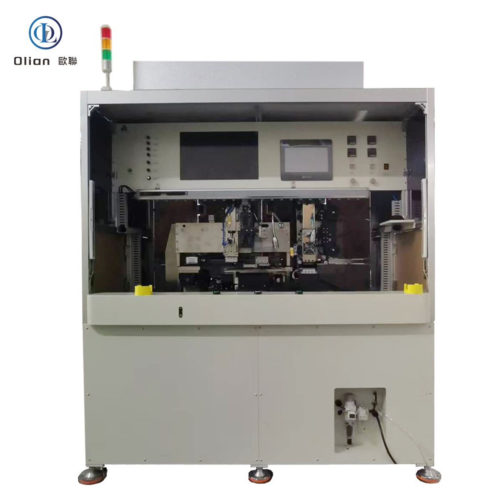
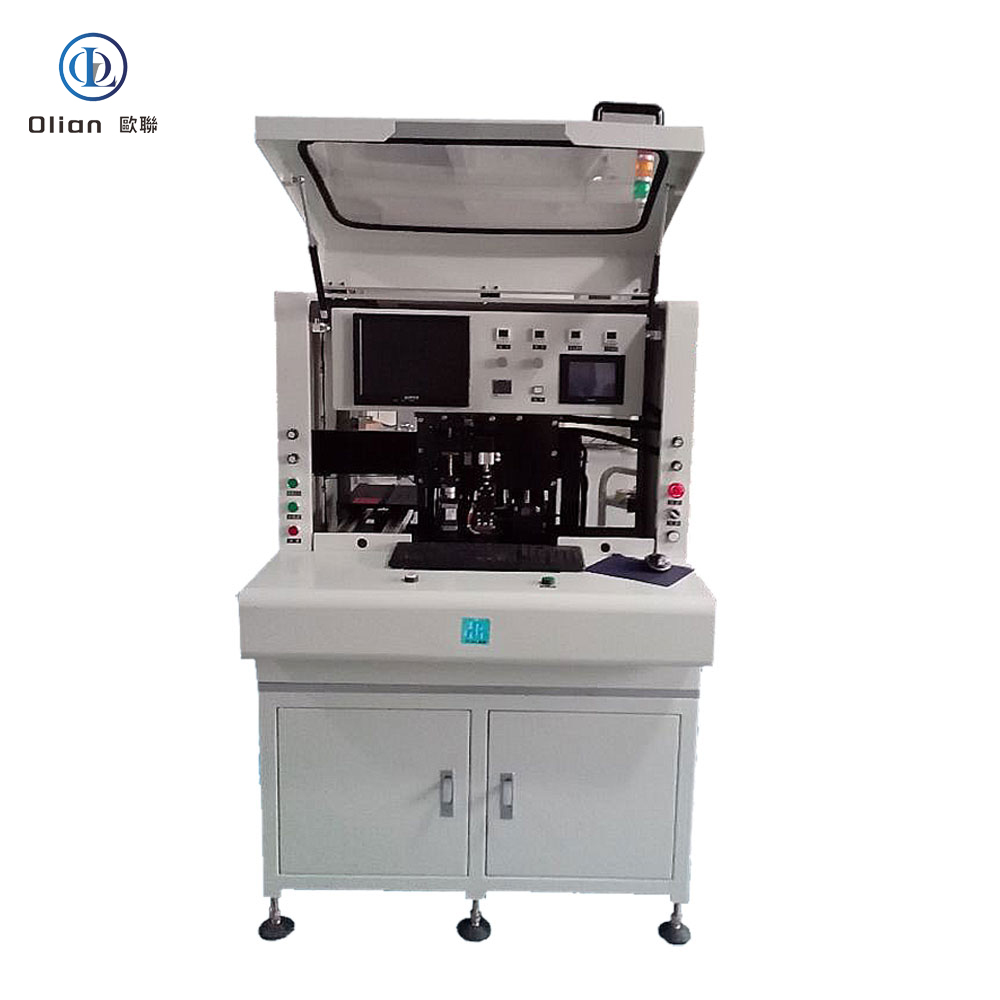
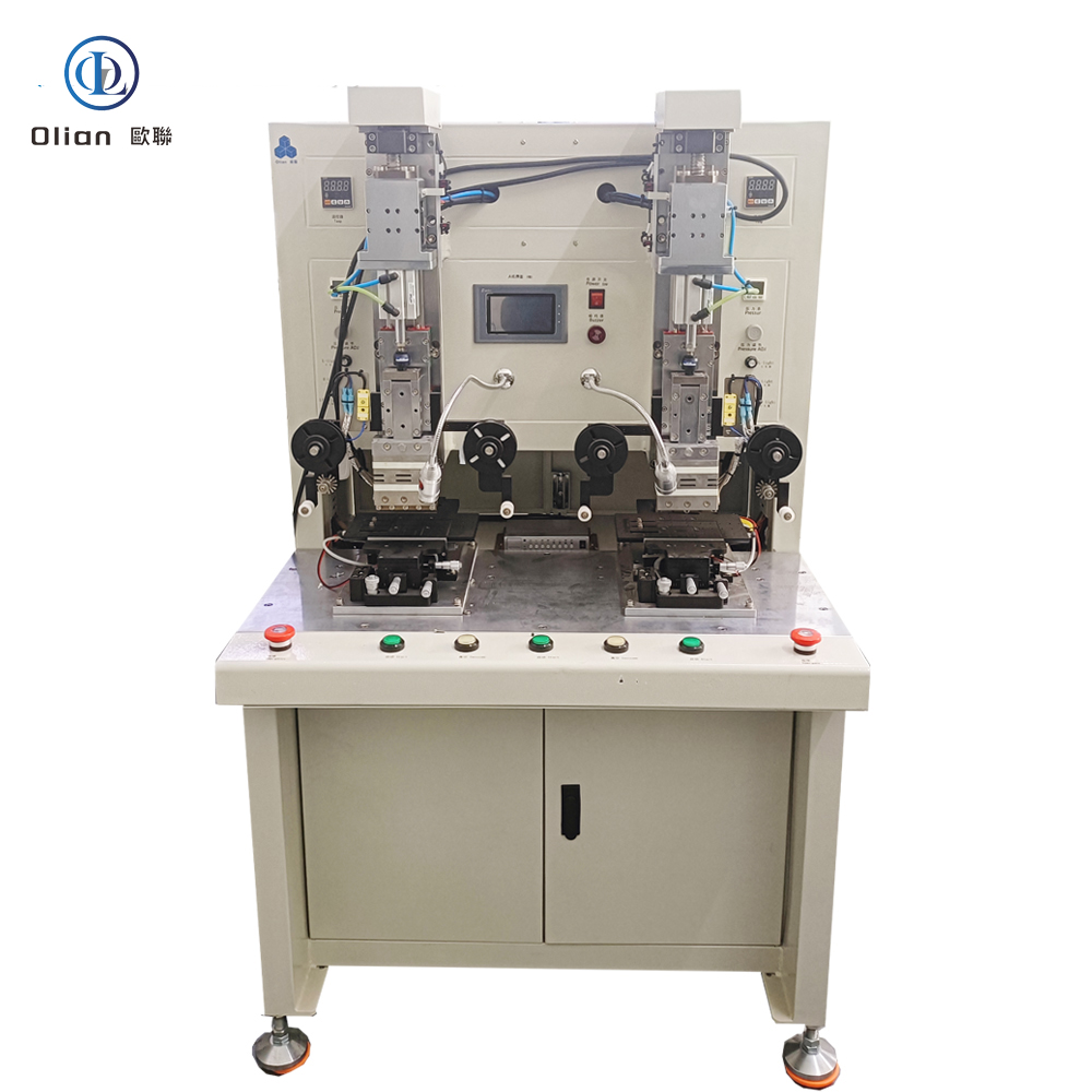
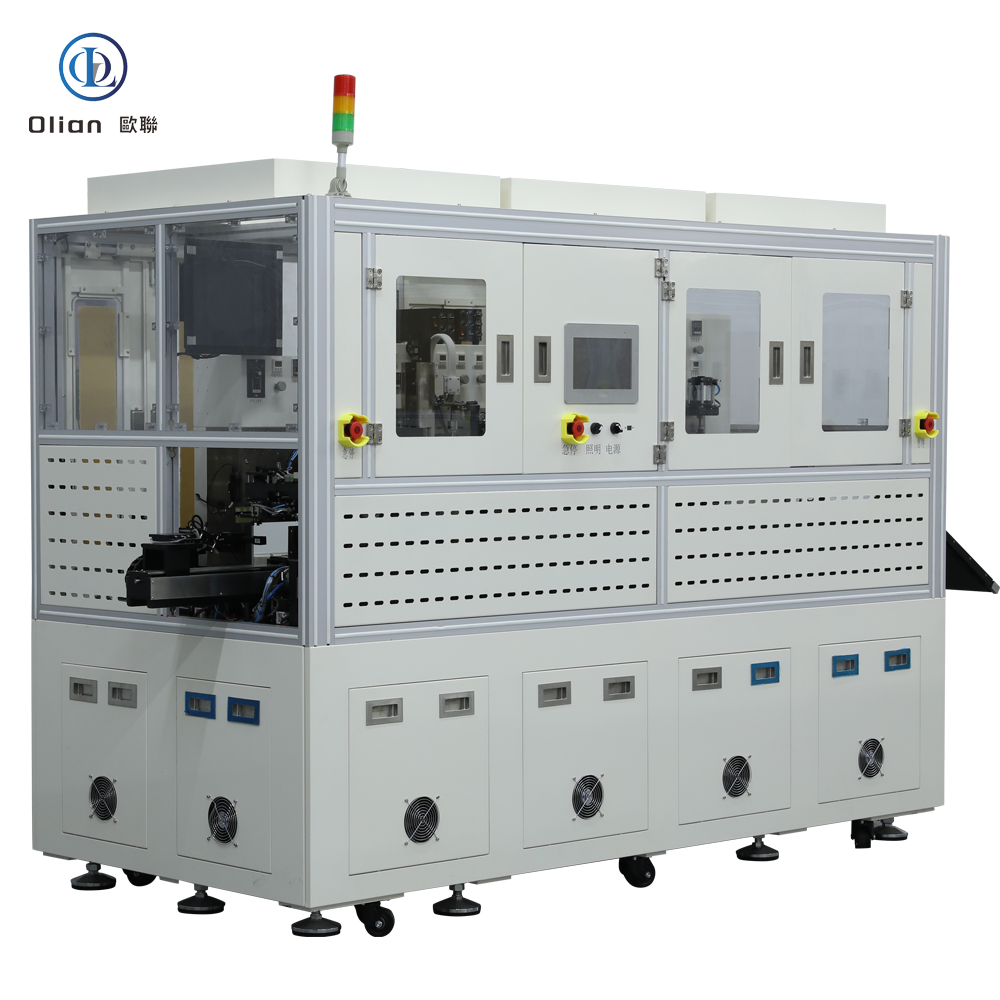
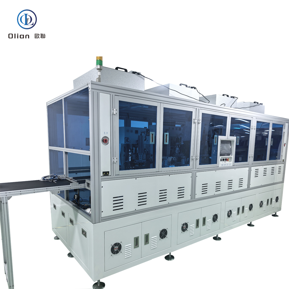
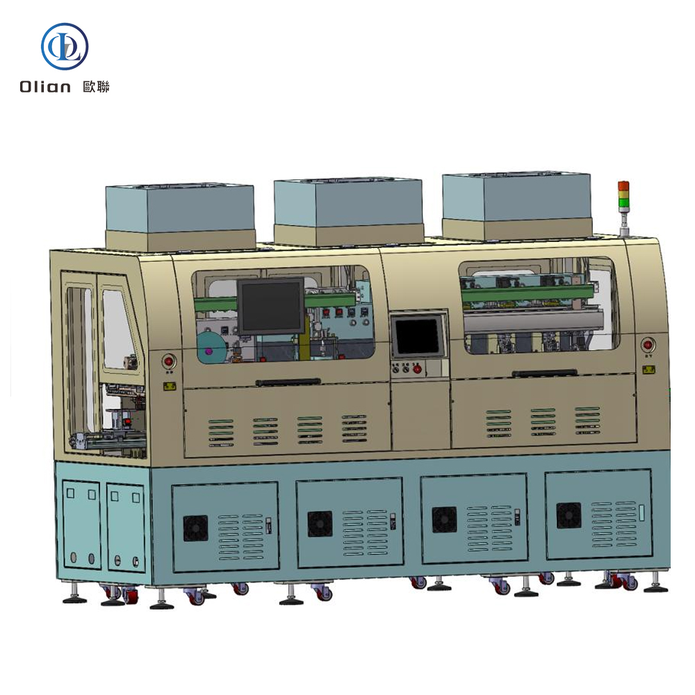
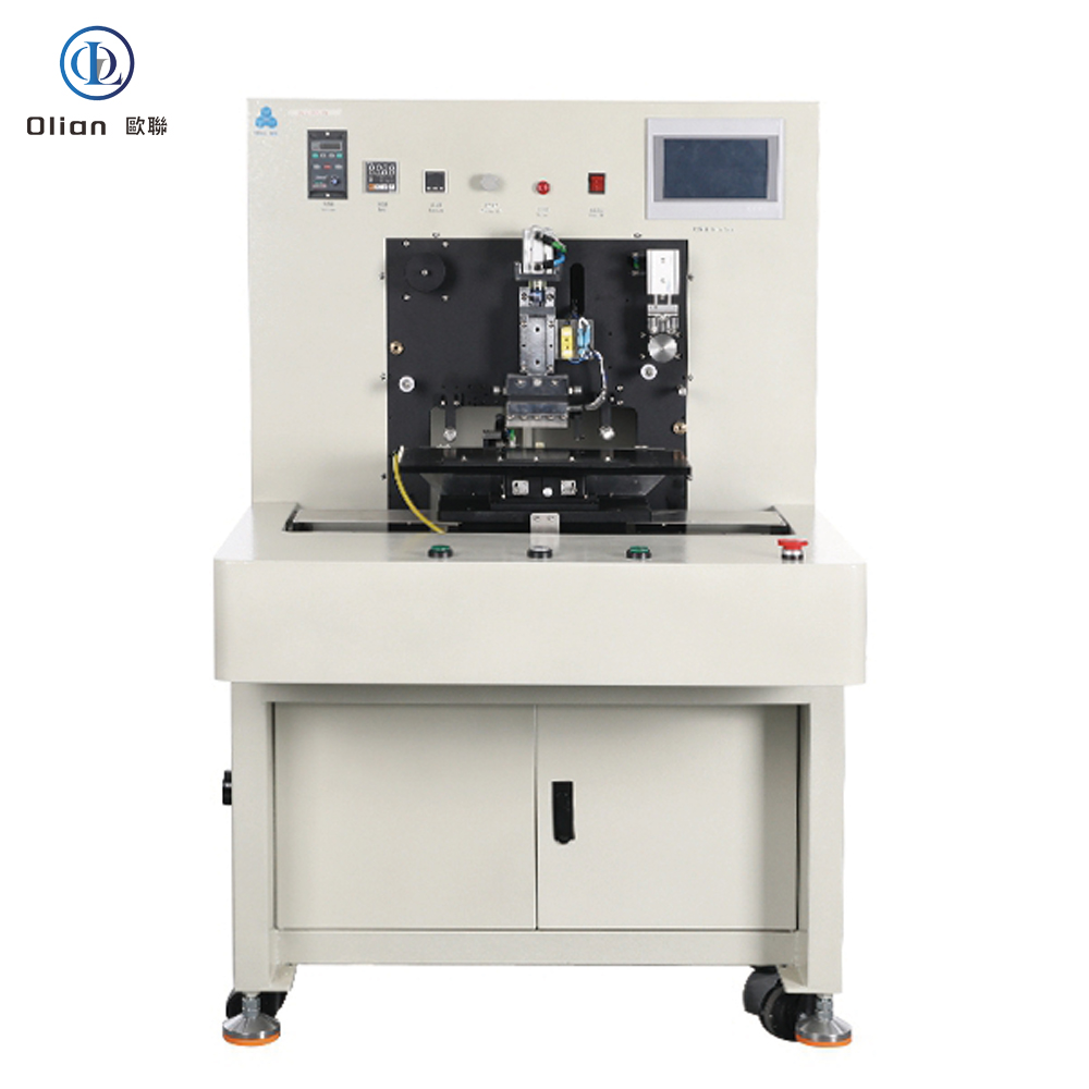
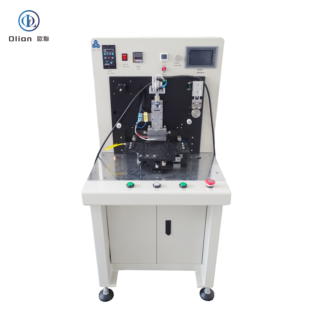
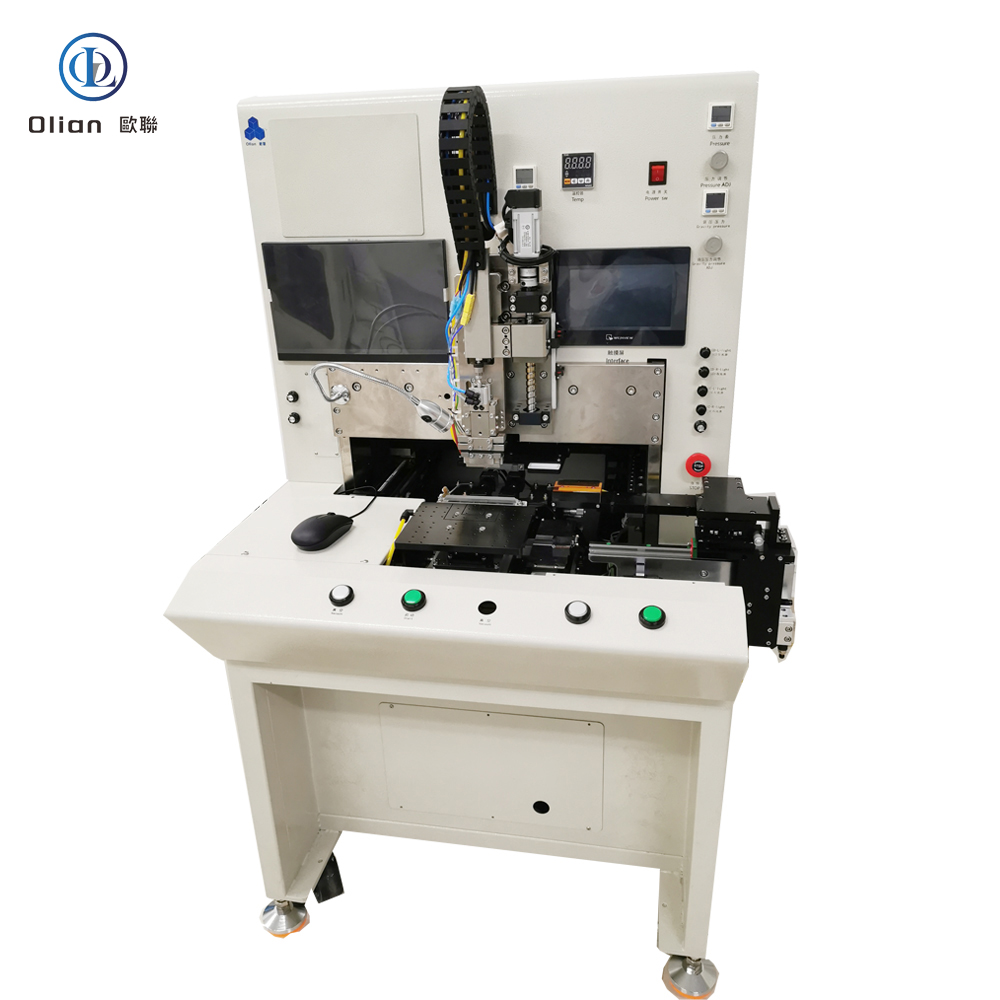
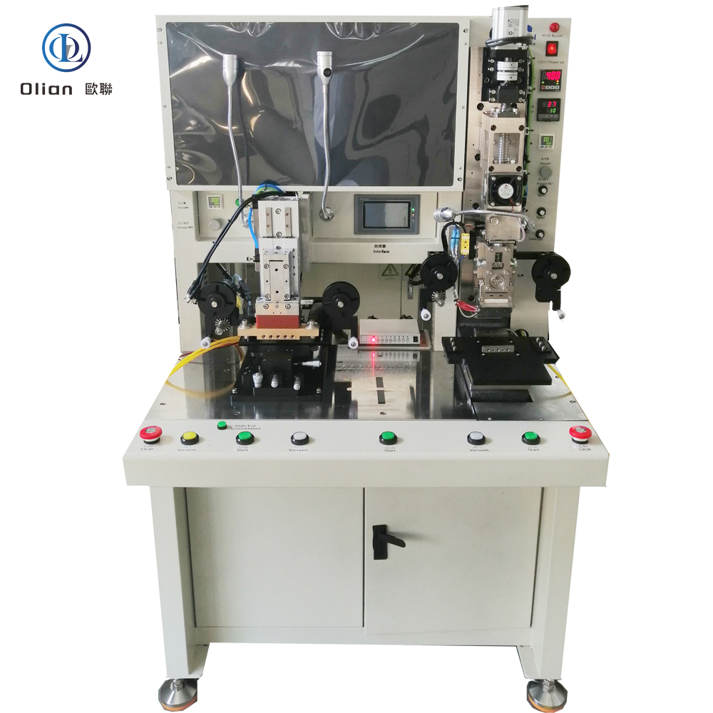
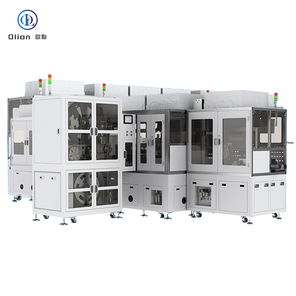
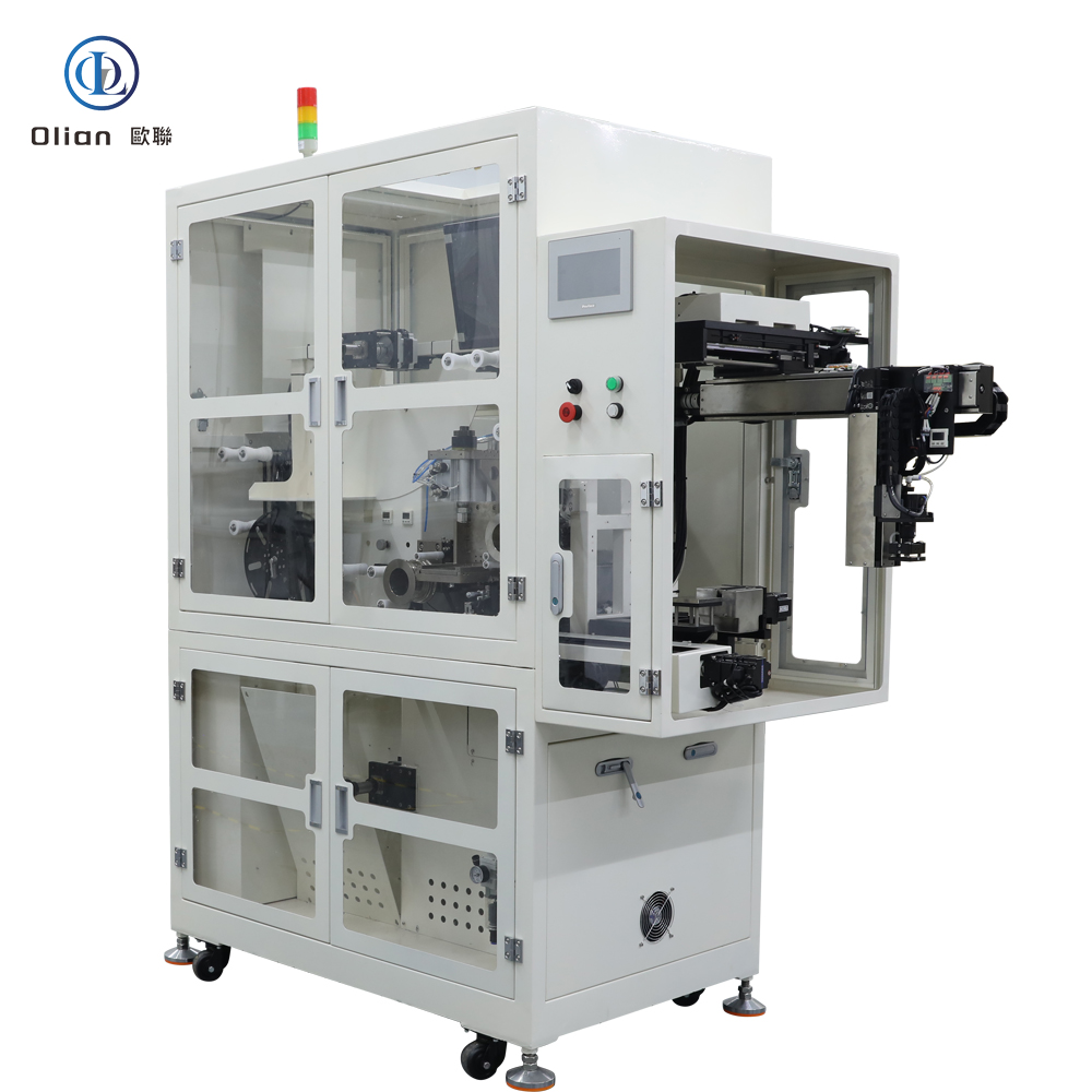
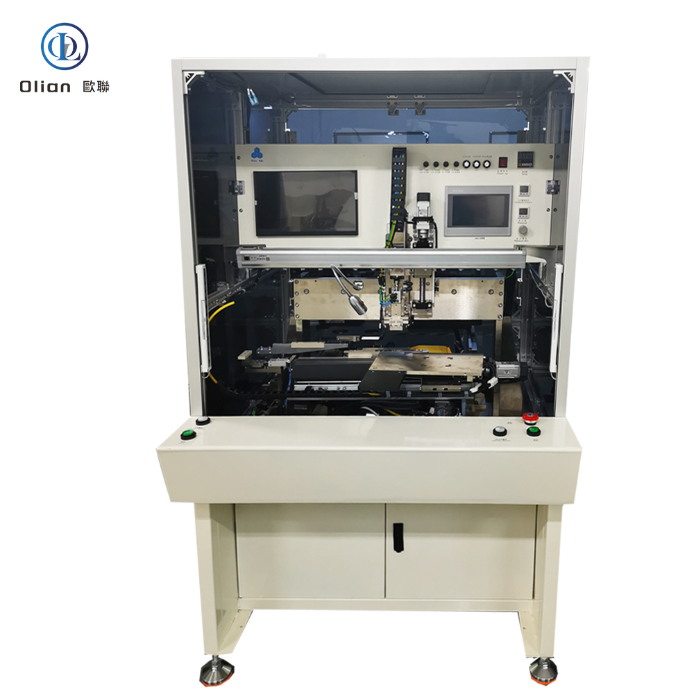
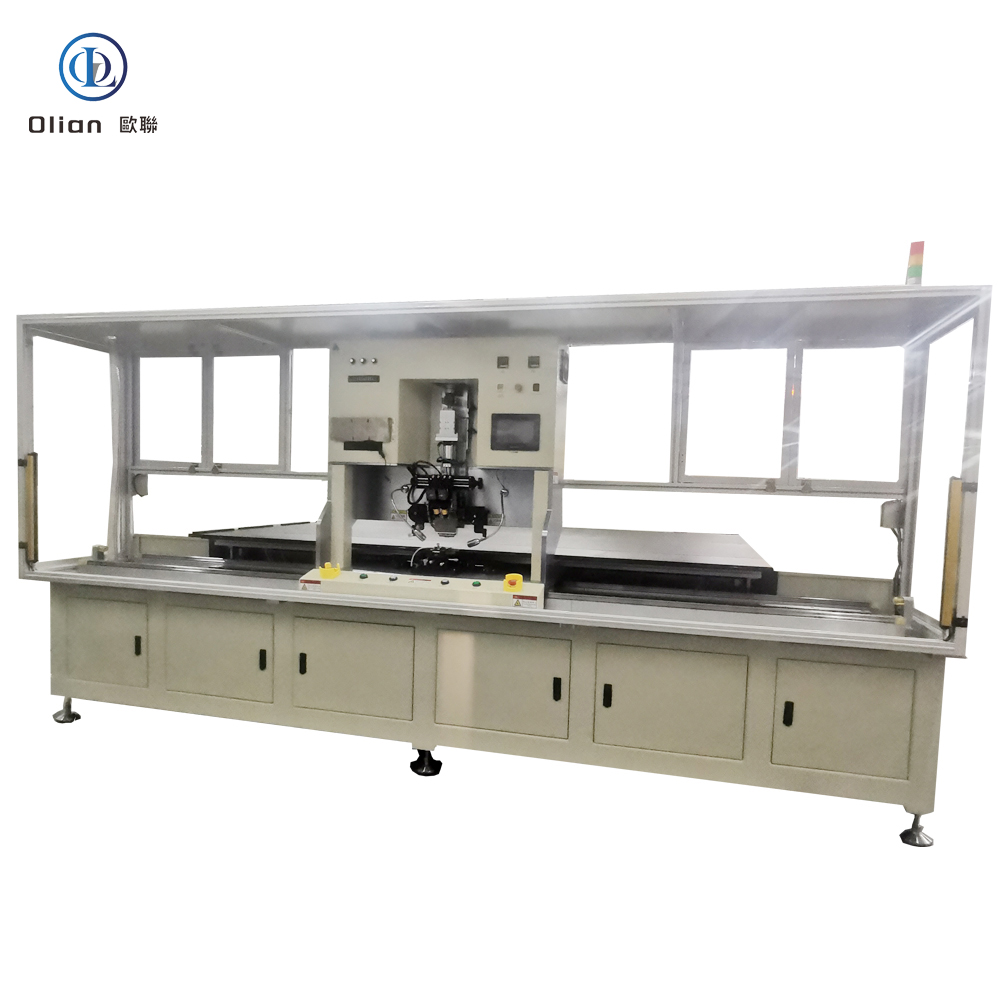
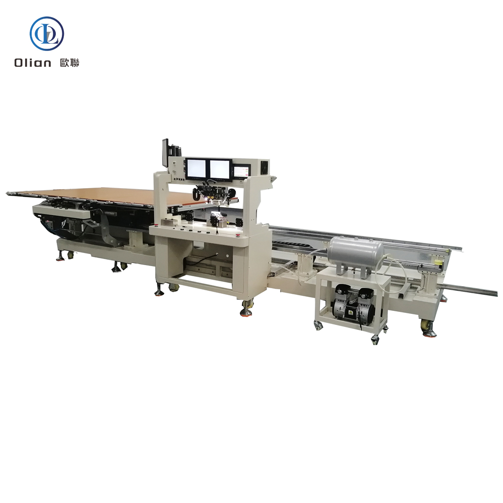
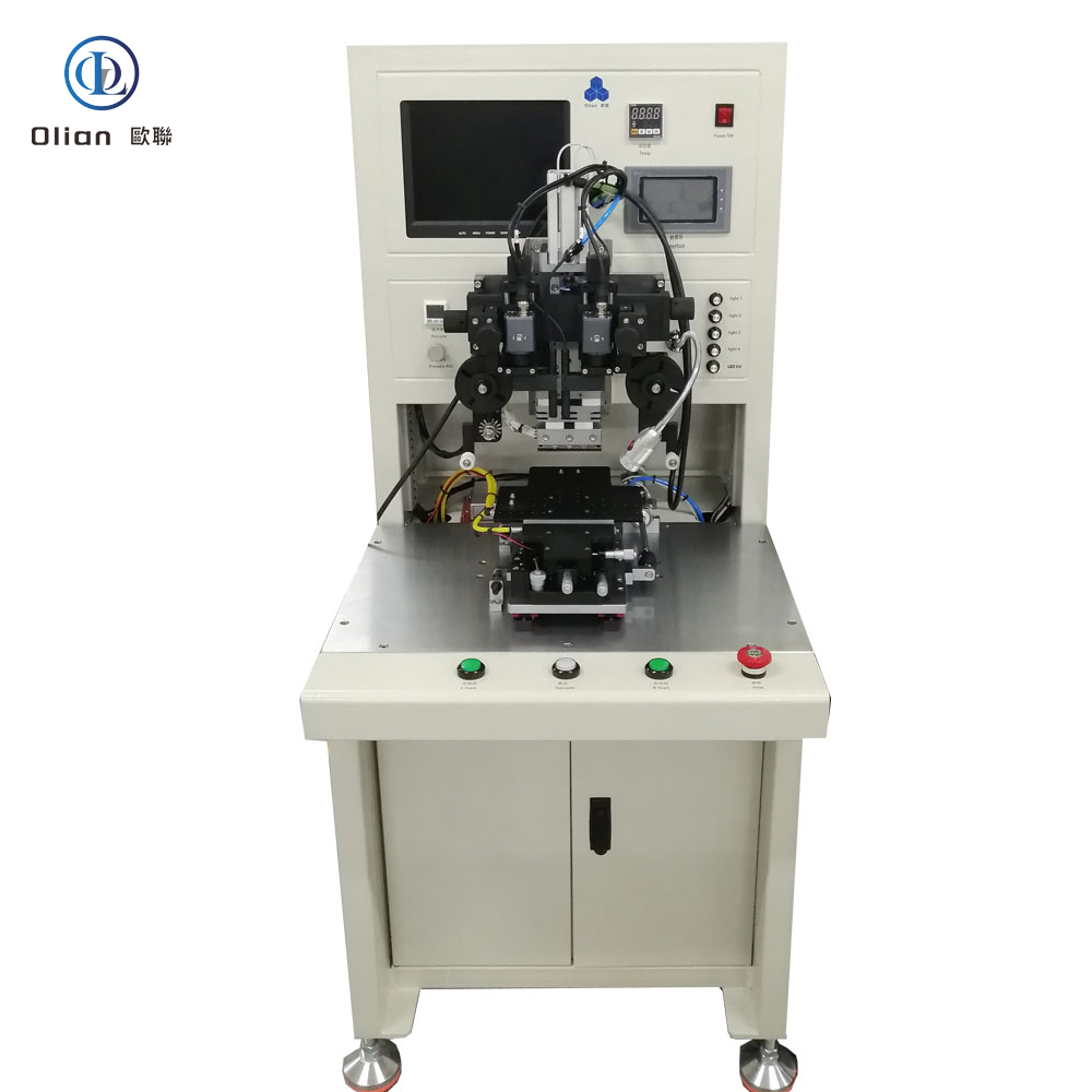
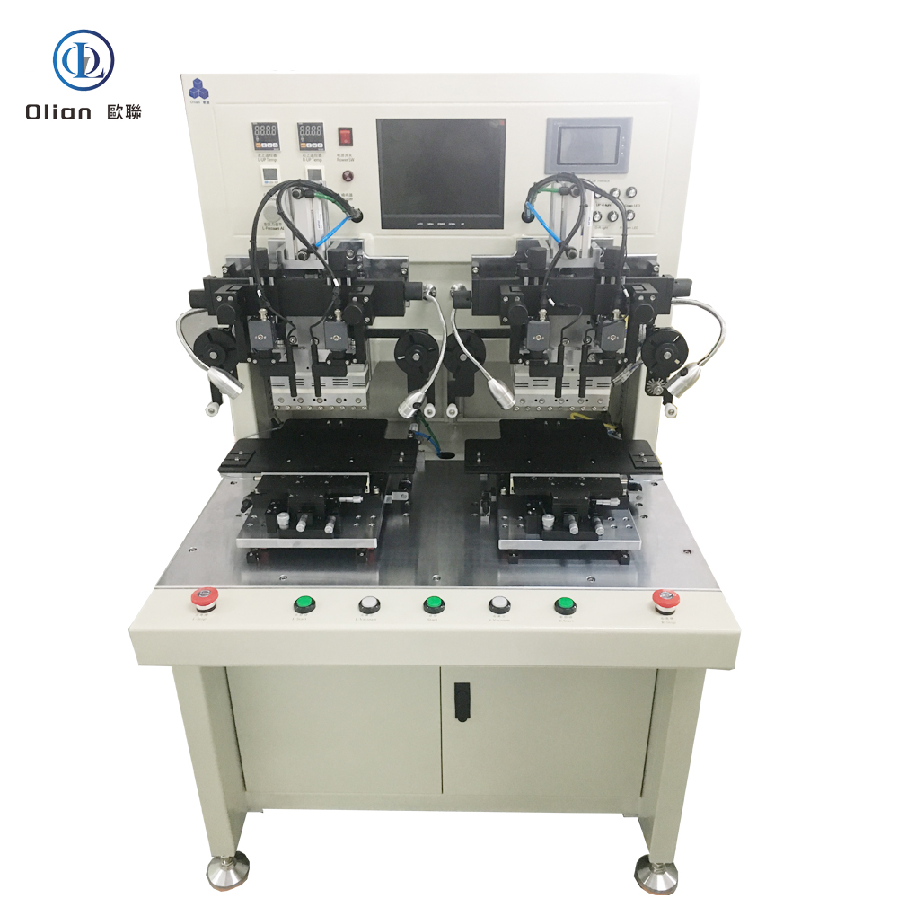
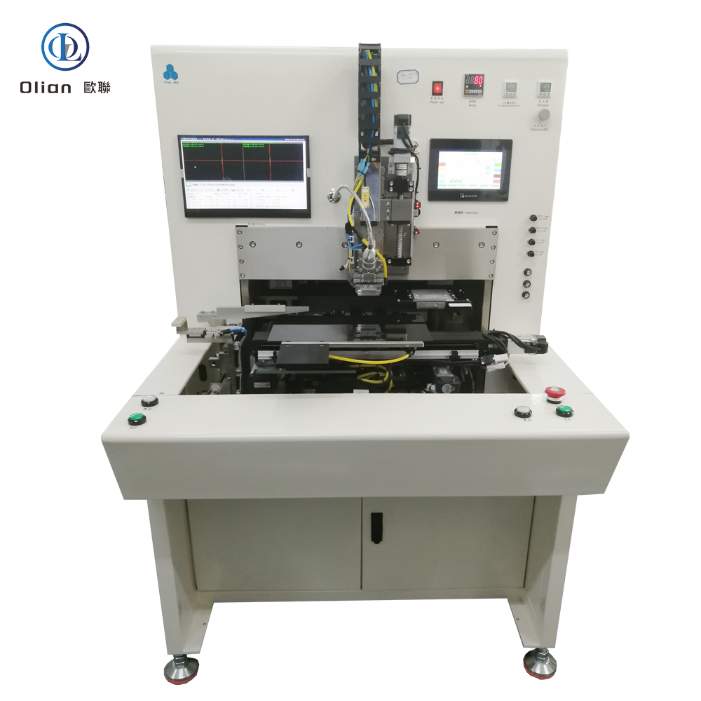
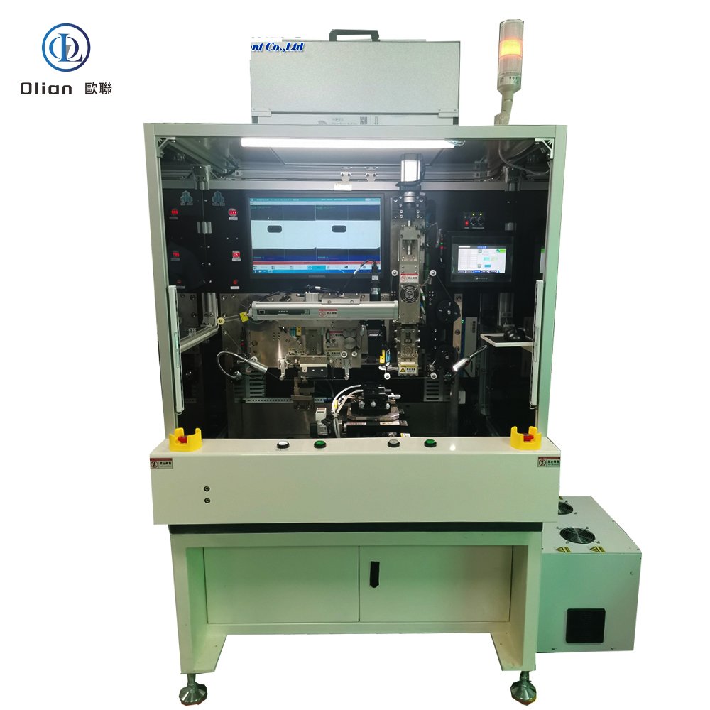
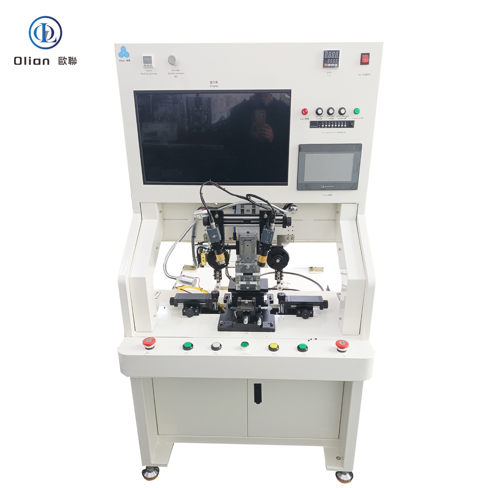
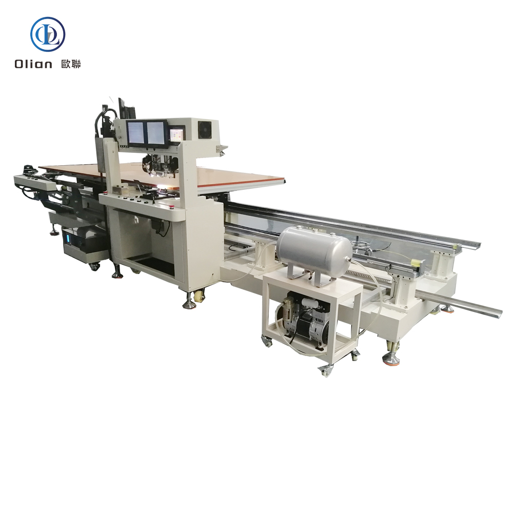
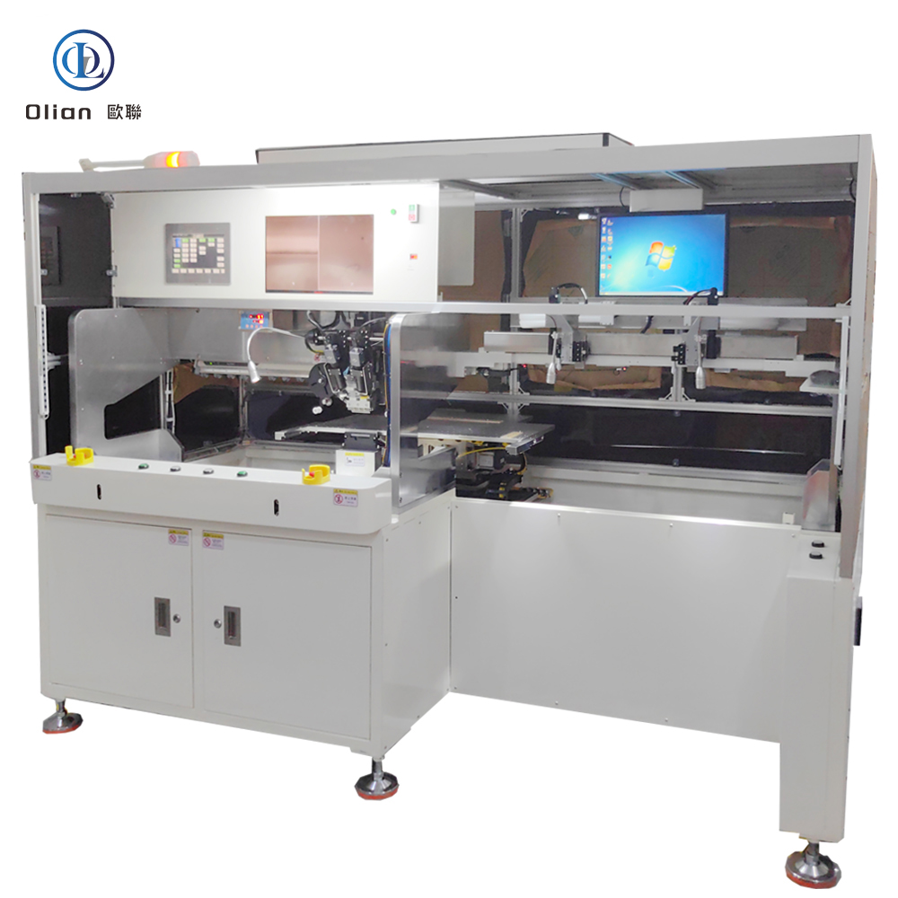
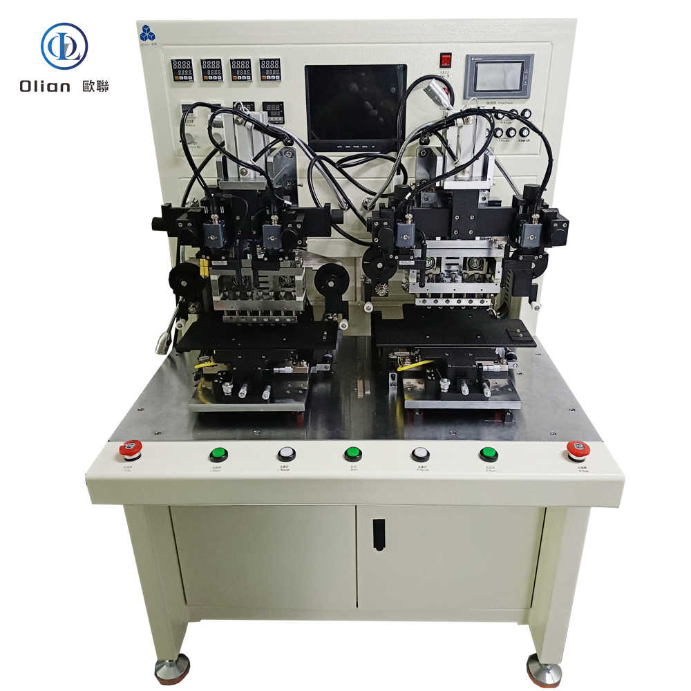
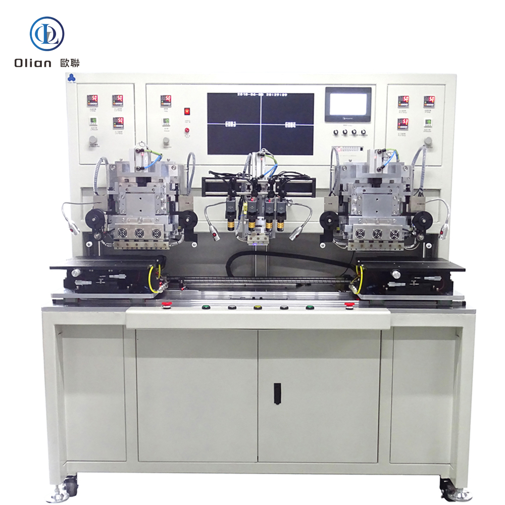
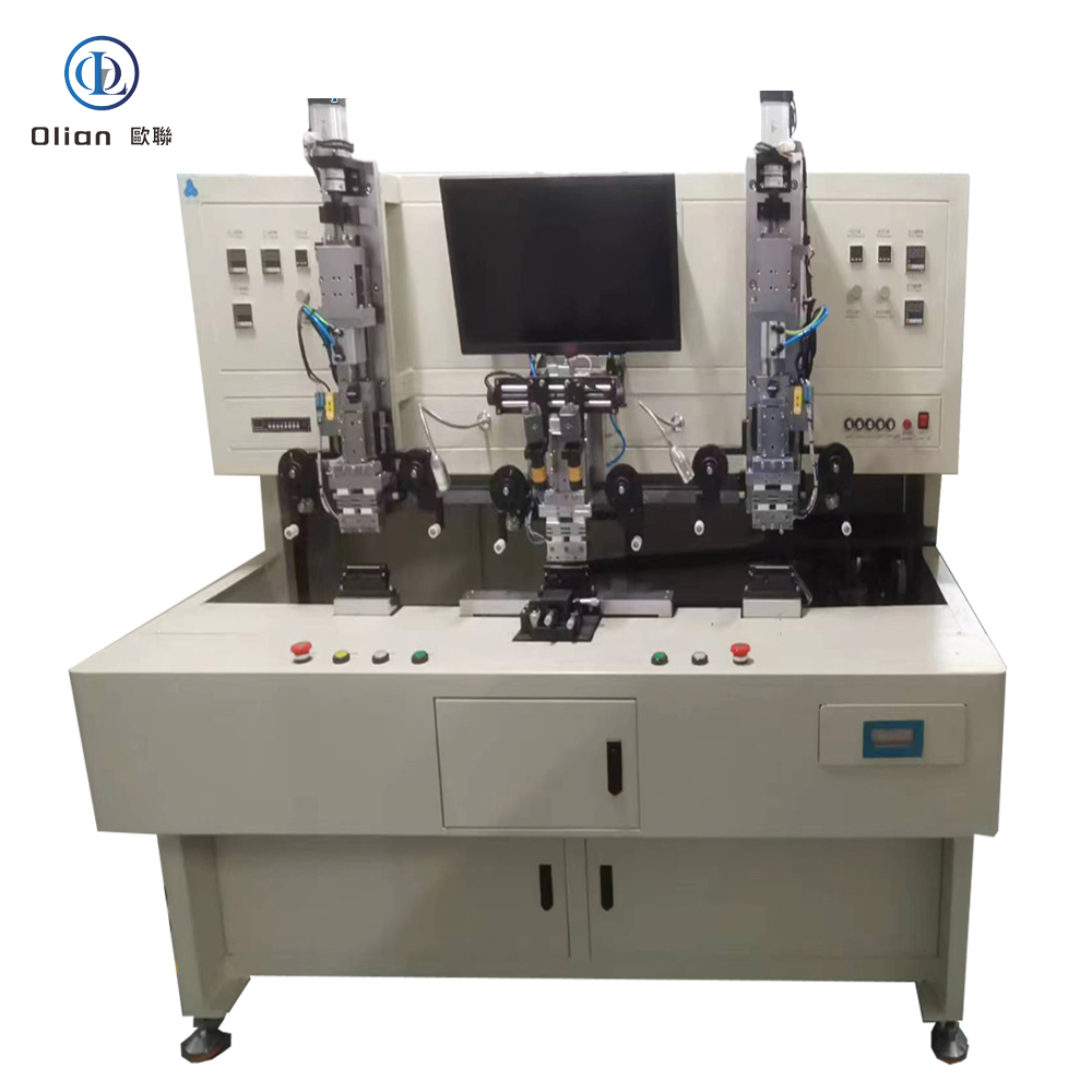
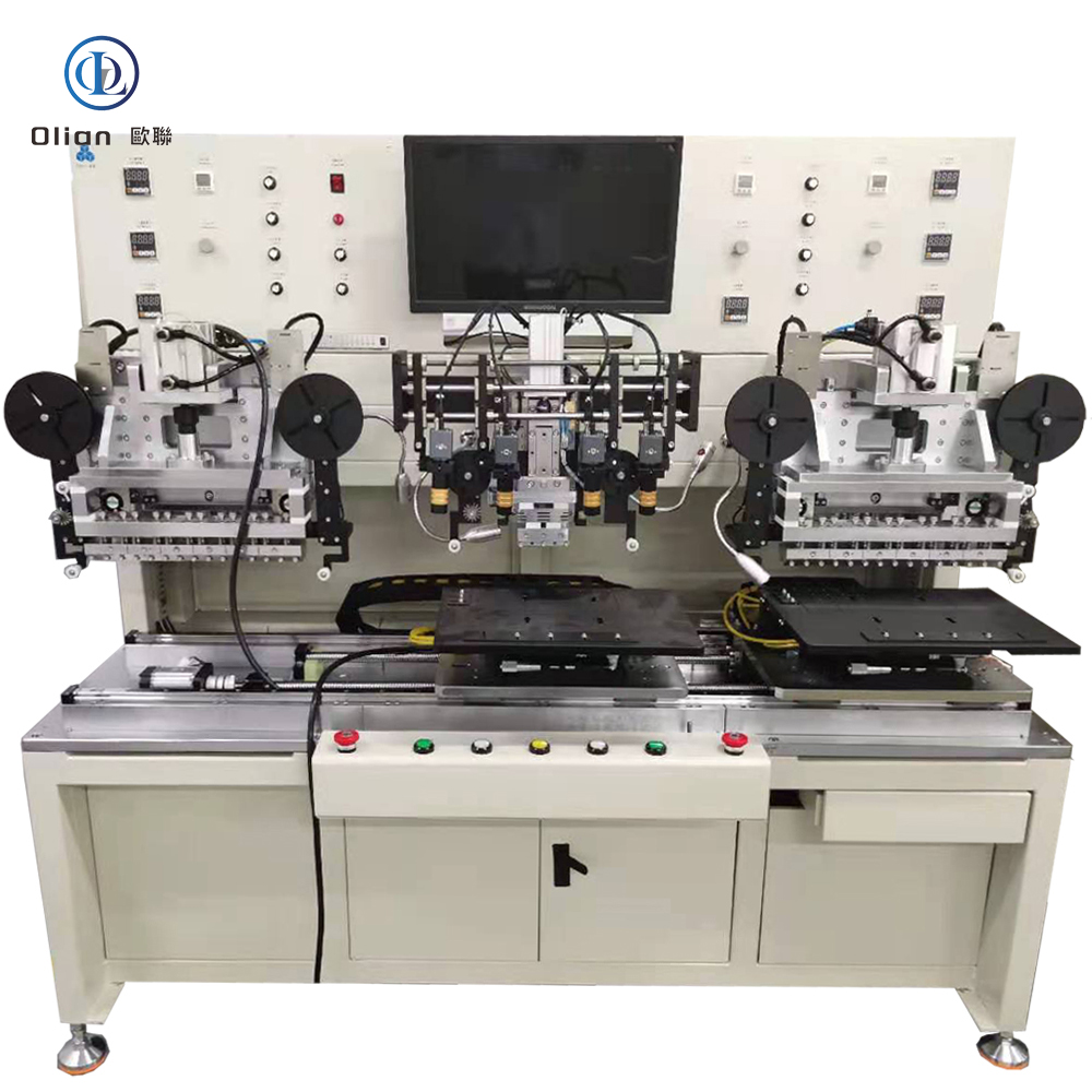
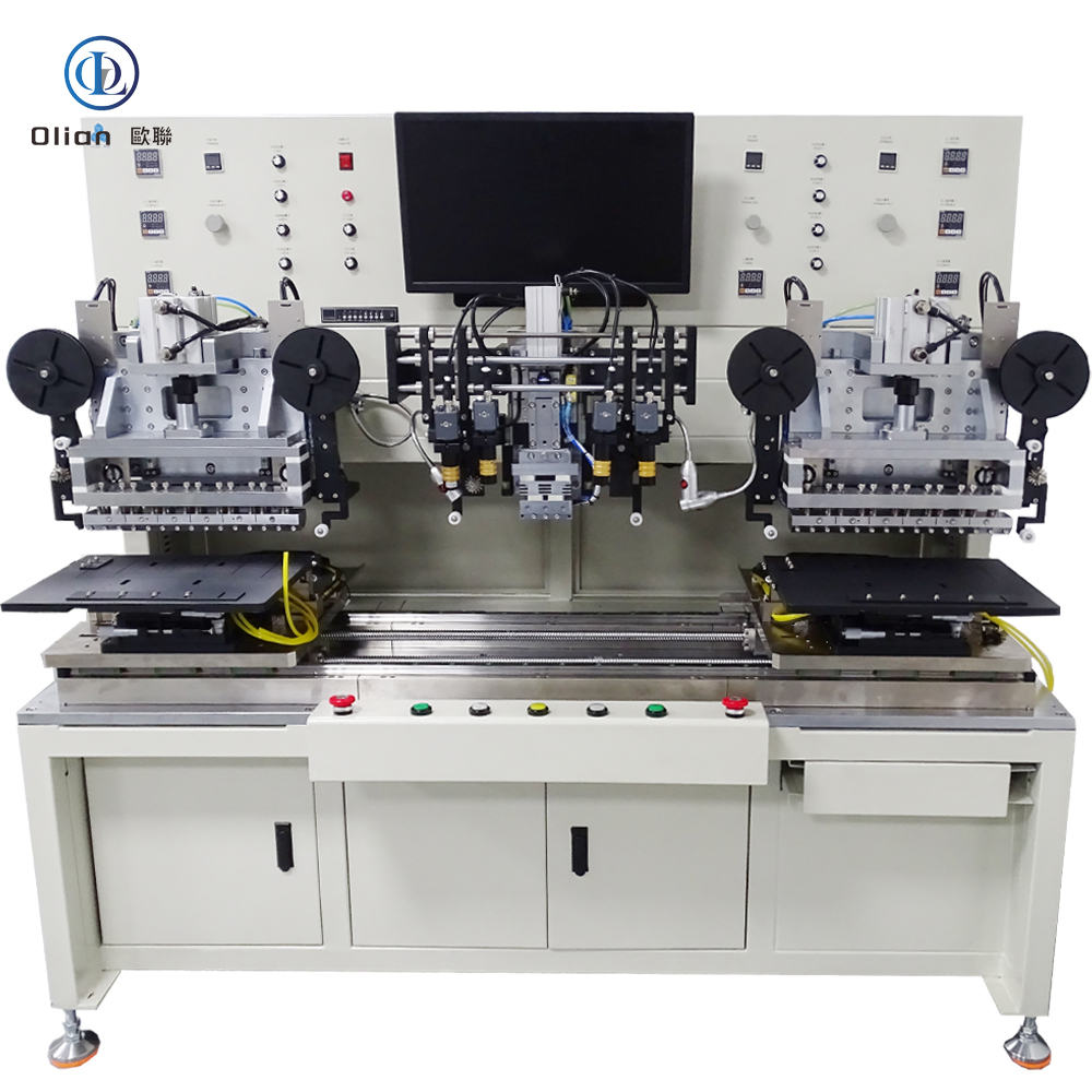
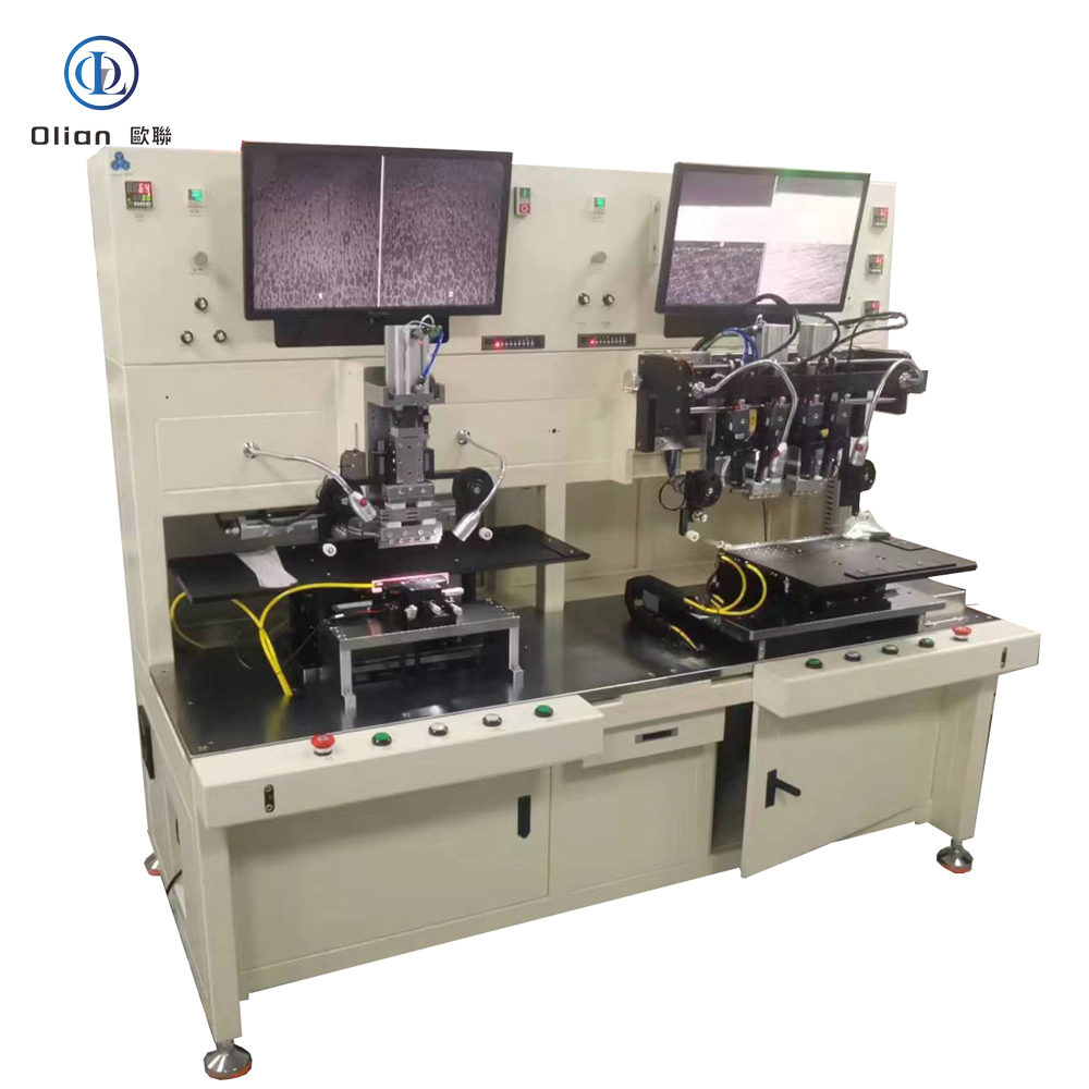
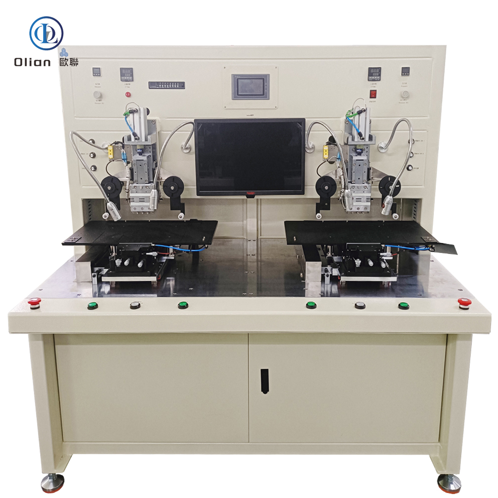
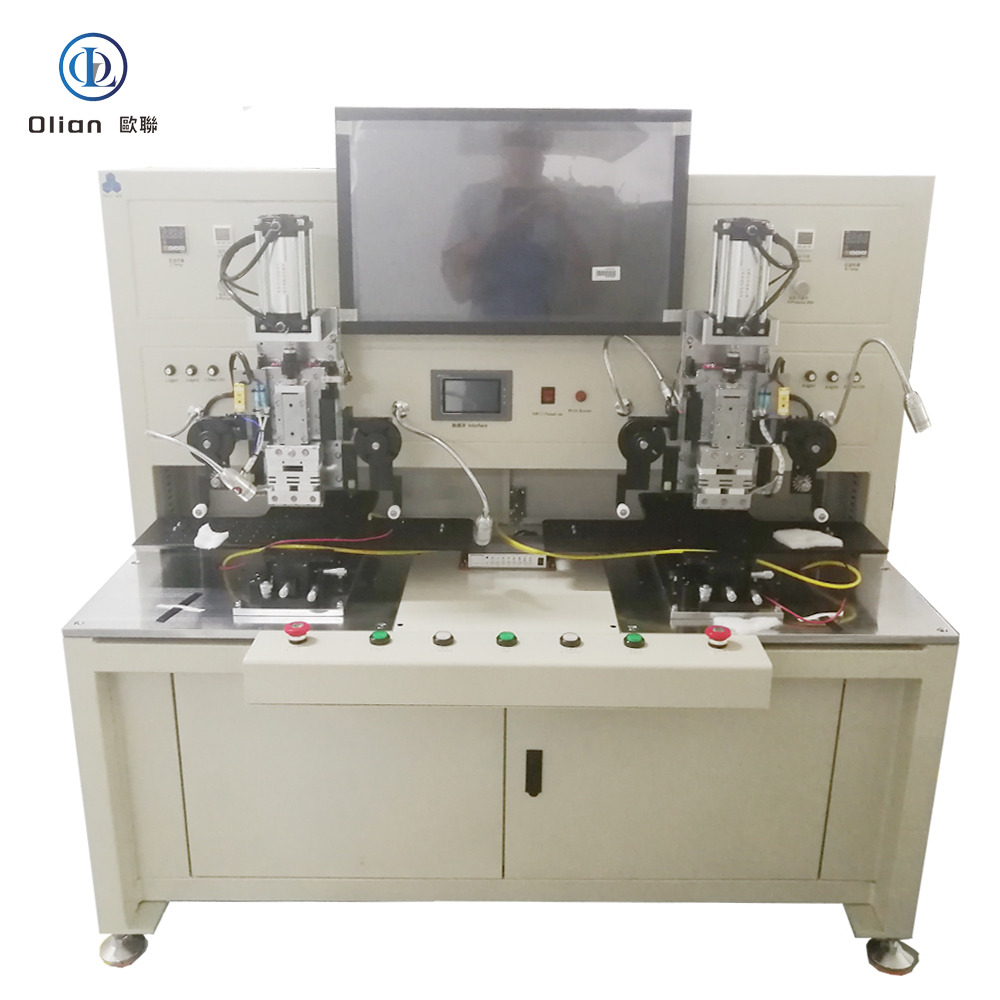
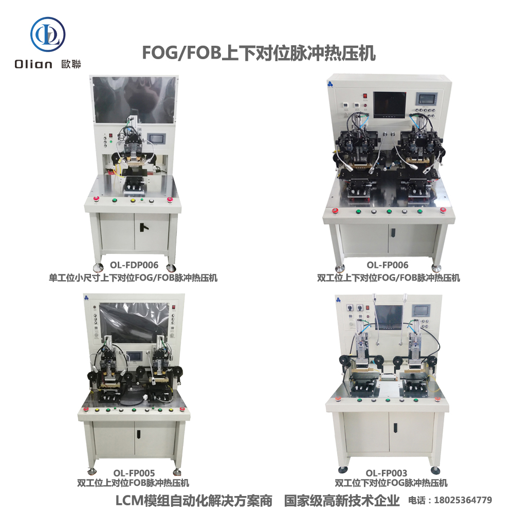
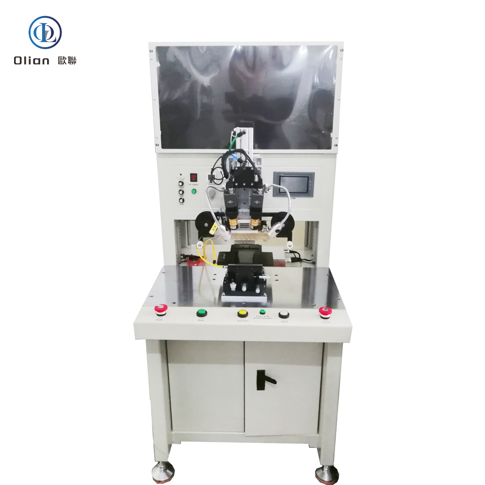
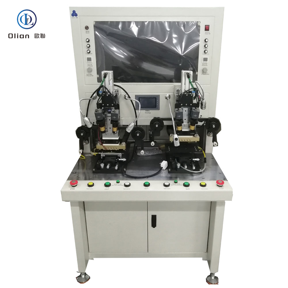
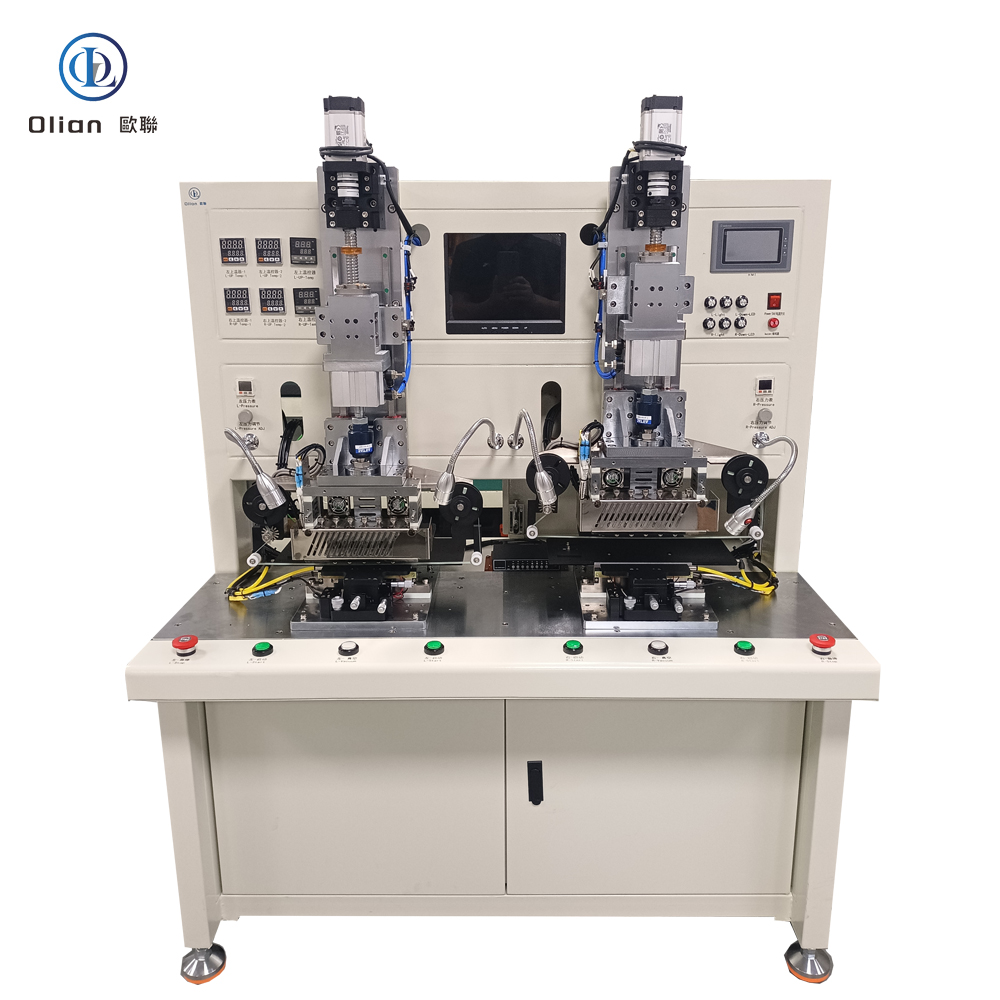
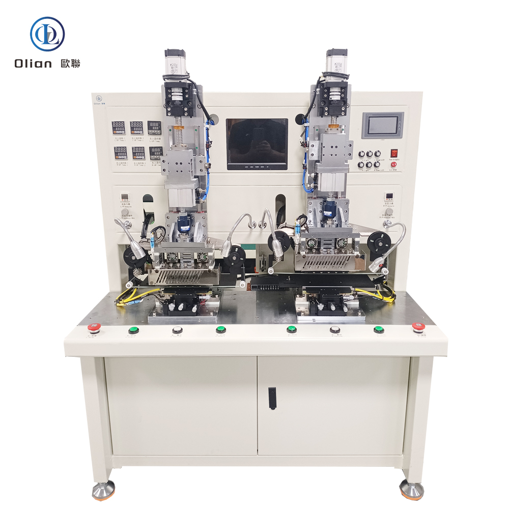
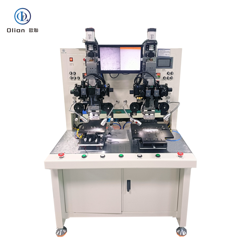
7-17inch semi automatic COF pre bonder7-17inch semi automatic COF pre bonder1-7inch semi automatic COF pre bonder1-7inch manual COF bonder1-7inch manual COF main bonder7-17inch semi automatic COF bonderfully automatic 1-7inch COF bonderfully automatic 7-17inch COF bonder
1. Why “COF” Still Dominates Large Displays
COG (Chip-On-Glass) works for phones, but 65-inch 8-K OLED panels generate too much heat to park the driver IC directly on the glass. COF moves the IC onto a flexible polyimide tail that can dissipate heat, fold 180°, and be replaced during repair. The COF bonder is the machine that welds that tail to the glass edge, enabling 0.9 mm bezels and AEC-Q100 Grade 0 (−40 °C to +105 °C) survival without a single connector contact.
2. What Exactly Is a COF Bonder?
A COF bonder is a servo-driven, vision-guided, pulse-heat press that:
Laminates anisotropic conductive film (ACF) onto glass or plastic,
Picks a bare driver IC from a diced wafer,
Places it face-down on the copper leads of a continuous polyimide reel,
Welds bumps into ACF at 180–220 °C and 1.0–1.5 MPa,
Repeats every 2.8 s while the reel indexes ±5 µm over 300 mm stroke.
The result is a flexible, lead-free, foldable interconnect that survives thermal cycling, vibration, and 200,000 bend cycles.
3. Physics: Why ACF + Pulse Heat Works
Gold or Copper Bumps 5–25 µm high are plated on the IC during wafer-level bumping.
ACF Film 25–45 µm thick contains 3–10 µm nickel or gold-coated spheres.
Pulse Heat: 180–220 °C in 1.5 s deforms spheres between bump and copper lead, creating < 30 mΩ vertical contacts while remaining > 1 GΩ isolated horizontally.
Cool Under Load: Water-cooled block drops to < 60 °C while pressure holds, locking particles in place.
4. Step-by-Step Fully Automatic Workflow
Reel Indexing: Servo motor advances polyimide tape; dancer-arm tension control maintains < 0.5 N fluctuation.
ACF Lamination: Precision cutter feeds 1–3 mm strip; heated roller tacks film to glass ITO at 80 °C, 0.2 MPa.
IC Pick-Up: Vacuum collet lifts die from waffle pack; ultrasonic sensor confirms presence; soft-tip ejector prevents silicon cratering.
AI Vision Alignment: Dual 12 MP cameras capture fiducials on bumps and copper leads; deep-learning algorithm calculates offset in X, Y, θ, and scale within ±1 µm @ 3σ in < 200 ms.
Pre-Bond: Head descends at 60 °C and 0.1 MPa to tack the IC; system verifies bump-to-lead overlap ≥ 98 %.
Pulse Heat Bond: Titanium head ramps 200 °C/s to 180–220 °C; pressure rises to 1.0–1.5 MPa; spheres deform and capture.
Cool Under Load: Water-cooled block drops to < 60 °C while pressure holds, preventing particle relaxation.
Cold-Laser Assist: Femtosecond laser pre-cleans ITO at 25 °C, enabling 120 °C PET bonds.
AI Yield Predictor: Neural networks forecast particle-trap probability, pushing yield to 99.9 %.
Servo-Hydraulic Hybrid: 80 kg force for 100-inch TV glass while maintaining 1 µm accuracy.
Roll-to-Roll COF: Reel-fed driver and touch tails bonded at 3,000 UPH .
According to industry analysis, the global COF bonder market is expected to grow at a CAGR of 6–8 % driven by 8-K TVs, foldable phones, and automotive displays
.
9. Applications Across All COF Processes
Consumer Electronics: Smartphone OLED (COG + COF touch), foldable hinge (COF to PI), tablet battery tail (COF to PCB)
A COF bonder is no longer a niche reel-fed press—it is the critical, AI-driven, cloud-connected gateway that turns continuous copper-clad polyimide into the 8-K TV source drivers, curved automotive clusters, and foldable touch sensors . By mastering sub-micron alignment, single-degree thermal control, and real-time force feedback, these platforms deliver 99.9 % yield and full Industry 4.0 traceability—future-proofing your process.
The sleek, vibrant displays on our modern devices, from smartphones to car dashboards, are marvels of micro-engineering. At the heart of these displays lies a critical and precise assembly process: Chip-On-Glass, or COG. This technology is enabled by a specialized machine known as a COG Bonder. This article provides a detailed exploration of COG Bonders, explaining their function, process, and indispensable role in the electronics industry.
What is a COG Bonder?
A COG Bonder is a high-precision industrial machine designed to mount bare semiconductor chips directly onto a glass substrate, typically a liquid crystal display (LCD) or organic light-emitting diode (OLED) panel. Unlike traditional methods that use packages and sockets, COG bonding creates a direct, space-saving connection between the integrated circuit (IC) and the glass. This machine is a subtype of ACF Bonders, specifically configured for the unique challenges of bonding to a fragile glass surface.
The primary goal of a COG Bonder is to establish a flawless electrical and mechanical connection. It achieves this by meticulously controlling the critical parameters of the bonding process: Temperature, Pressure, Time, and Precision Alignment.
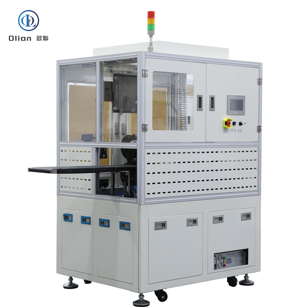
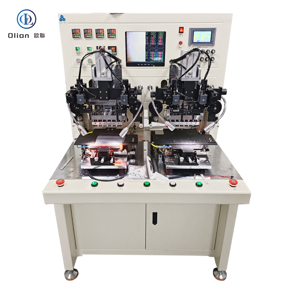
COG BONDERCOG BONDERCOG BONDER
The Critical Components of a COG Bonder
A modern COG Bonder is an integration of several sophisticated subsystems:
Precision Stage: A highly stable platform that holds the glass substrate. It can move in the X, Y, and theta (rotation) axes with micron-level accuracy for alignment.
Bonding Head (Thermode): This is the tool that applies the necessary heat and pressure. It is custom-designed to match the specific size and pattern of the chip being bonded.
Vision Alignment System: This is arguably the most crucial subsystem. It consists of high-resolution cameras and advanced image processing software. It automatically identifies alignment marks on both the glass substrate and the semiconductor chip to ensure perfect placement before bonding.
Pick-and-Place Unit: A robotic mechanism that picks up the bare die (chip) from a wafer or waffle pack and transports it to the bonding location with extreme care to prevent damage.
Control Software: The brain of the machine, which allows operators to set and monitor all bonding parameters (force, temperature, time) and manage recipes for different products.
The Detailed COG Bonding Process Step-by-Step
The COG bonding process is a sequence of meticulously orchestrated steps:
Preparation and Loading: The glass substrate is cleaned and loaded onto the machine’s stage. Meanwhile, the driver ICs, in the form of bare dies, are supplied from a wafer tape or a gel pack.
ACF Application (Pre-Lamination): A piece of Anisotropic Conductive Film (ACF) is precisely cut and applied to the bonding area on the glass. A preliminary thermode lightly presses the film at a low temperature to temporarily fix it in place. This step is called pre-lamination.
Chip Pick-Up and Alignment: The pick-and-place unit uses a vacuum collet to pick up a single chip. The vision system then captures the image of the chip’s bonding pads. Simultaneously, the stage moves to align the corresponding pads on the glass substrate. The software calculates any positional offset and makes minute corrections to ensure perfect overlap.
Main Bonding: This is the core of the process. The bonding head descends, pressing the chip onto the glass substrate with a specific force. Simultaneously, it heats the chip to a predetermined temperature (typically between 180°C and 250°C) for a set duration.
Under this combination of heat and pressure, the conductive particles within the ACF are compressed between the chip’s bumps and the glass substrate’s electrodes, forming electrical connections.
The thermosetting adhesive in the ACF cures, forming a strong, permanent mechanical bond and encapsulating the connections to prevent short circuits.
Cooling and Unloading: After the bonding time elapses, the thermode retracts. The assembly is often allowed to cool slightly before being unloaded. The result is a driver IC permanently and directly attached to the glass, ready for the next steps in the display module assembly.
Key Advantages of COG Bonding Technology
The adoption of COG bonding offers significant benefits for display manufacturing:
Space Savings: By eliminating the need for a plastic package and a flexible cable connection, COG significantly reduces the border area (bezel) of the display. This is essential for modern devices with ultra-thin bezels.
High Reliability: The direct connection minimizes the number of interconnects, reducing potential failure points. The encapsulation by the ACF provides excellent resistance to moisture, dust, and mechanical shock.
Fine-Pitch Capability: COG bonding can achieve extremely fine interconnect pitches, allowing it to keep pace with the trend of higher-resolution displays that require more densely packed driver connections.
Cost-Effectiveness: It simplifies the overall display module structure by removing components like the chip package and tape carrier, leading to a lower bill of materials.
Improved Electrical Performance: Shorter signal paths between the driver chip and the display electrodes reduce inductance, capacitance, and signal delay, enhancing display performance.
Applications of COG Bonders
COG bonding is the dominant technology for attaching driver ICs in a vast range of display products:
The COG Bonder is a masterpiece of precision engineering that operates behind the scenes to make our modern display-centric world possible. Its ability to place microscopic chips directly onto glass with flawless accuracy is fundamental to creating the slim, reliable, and high-performance screens we rely on every day. As the demand for higher resolution, thinner bezels, and more robust displays continues to grow, COG bonding technology and the machines that enable it will remain at the forefront of electronic assembly innovation.
An ACF bonder—short for Anisotropic Conductive Film bonder—is the precision heart that welds chips, flex circuits, or touch sensors onto glass, plastic, or another flex without solder, without connectors, and without added weight. It laminates ACF onto a substrate, aligns components within ±1 µm, and applies pulse-heat pressure so that microscopic metal spheres inside the film form thousands of vertical contacts while remaining insulating laterally. Every smartphone OLED, foldable hinge, 8-K TV source driver, and curved automotive cluster you touch has passed through such a bonder. This guide explains physics, hardware, software, specs, applications, trends, and maintenance so Google instantly ranks you for “ACF bonder”, “ACF bonding machine”, “pulse-heat ACF bonder”, “automatic ACF laminator”, and every high-value permutation.
Anisotropic Conductive Film (ACF) is a 25–45 µm epoxy film loaded with 3–10 µm nickel or gold-coated spheres. Under heat (80–220 °C) and pressure (0.2–1.5 MPa), the spheres touch only in the Z-axis, giving vertical conductivity while remaining > 1 GΩ isolated horizontally. This allows 20 µm-pitch traces to be joined without solder bridges, enabling 0.9 mm bezels, 200,000-fold cycles, and −40 °C to +105 °C automotive survival
.
2. Physics: The Two-Stage Dance
ACF Lamination (Tack): Low temperature (80 °C) and low pressure (0.2 MPa) activate the adhesive just enough to hold the film in place.
Final Bond: High temperature (140–220 °C) and high pressure (0.6–1.5 MPa) deform the spheres between opposing pads, creating < 30 mΩ vertical contacts while the adhesive cures .
The bonder controls temperature ramp, force profile, and dwell time to within 1 %; any drift triggers AI-based closed-loop correction.
3. Step-by-Step Fully Automatic Workflow
Robot Loading: 6-axis arm feeds glass, flex, or plastic reel; barcode scanner confirms product ID.
Atmospheric Plasma Cleaning: Raises surface energy to > 60 dynes for ACF wetting.
ACF Lamination: Precision cutter feeds 1–3 mm strip; heated roller tacks film at 80 °C, 0.2 MPa.
Cold-Laser Assist: Femtosecond laser pre-cleans ITO at 25 °C, enabling 120 °C PET bonds.
AI Yield Predictor: Neural networks forecast particle-trap probability, pushing yield to 99.9 %.
Servo-Hydraulic Hybrid: 80 kg force for 100-inch TV glass while maintaining 1 µm accuracy.
Roll-to-Roll ACF: Reel-fed driver and touch tails bonded at 3,000 UPH.
According to industry analysis, the global ACF bonder market is expected to grow at a CAGR of 6–8 % , driven by foldable phones, automotive displays, and medical wearables
An ACF bonder is no longer a niche press—it is the universal, AI-driven, cloud-connected gateway that turns naked silicon, floppy polyimide, and curved glass into the foldable phones, 8-K TVs, and transparent medical patches . By mastering sub-micron alignment, single-degree thermal control, and real-time force feedback, these platforms deliver 99.9 % yield and full Industry 4.0 traceability—future-proofing your process.
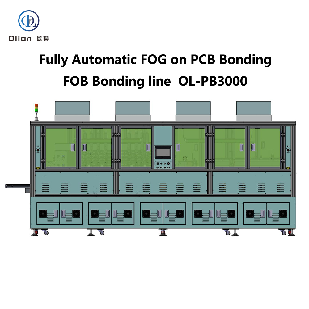
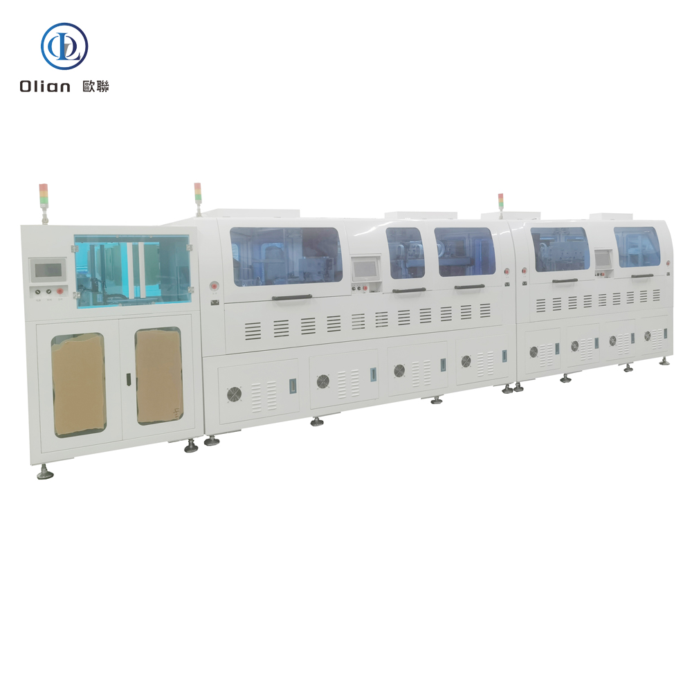
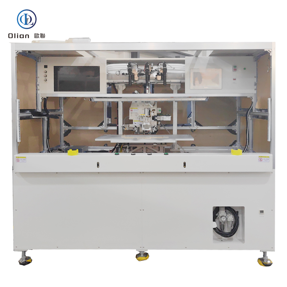
Fully Automatic COG COF COP FOG FOF Bonding Machine
A fully automatic COG COF COP FOG FOB FOF TFOG bonding machine is the precision heart of every modern display factory. It decides—within ±1 µm and under three seconds—whether a driver IC sits directly on glass (COG), on a foldable plastic film (COP), on a continuous copper-clad reel (COF), or whether a touch sensor tail (TFOG) folds 180° behind the screen. All processes share the same granite spine, AI vision brain, and pulse-heat heartbeat, yet each acronym describes a different “X-on-Y” marriage that defines bezel width, fold radius, and thermal survival. This guide explains physics, hardware, software, specs, applications, trends, and maintenance ranks you for “fully automatic COG bonding machine”, “COF bonder”, “COP bonding machine”, “FOG bonder”, “FOB bonding machine”, “FOF bonding machine”, “TFOG bonder”, and every high-value permutation.
1. Why “Fully Automatic” Matters
Manual loading, hand-alignment, and operator-dependent pressure are no longer acceptable when bezels shrink to 0.9 mm and foldable phones must survive 200,000 bends. A fully automatic bonding machine integrates:
Robot Loaders: 6-axis arms or SCARA pickers feed glass, flex, or plastic reels without human touch.
AI Vision Alignment: 12 MP dual cameras + deep-learning edge detection achieve ±3 µm @ 3σ in < 200 ms.
Pulse-Heat Engine: 200 °C/s ramp, ±0.5 °C closed-loop, overshoot < 1 °C.
Force-Feedback Loop: Voice-coil or servo motor, 0.1 g resolution, 2 ms response; active gravity cancellation for 25 µm PET.
MES/Cloud Link: OPC-UA uploads every temperature, pressure, and resistance curve; AI predicts heater life 200 cycles ahead.
Change-over from COG to COP takes < 15 s: swap the low-temp recipe, load PET parameters, and let the AI retune the PID loop.
2. Physics Common to All “X-on-Y” Flavours
Bump Formation: Gold or copper bumps 5–25 µm high are plated on the IC during wafer-level bumping.
ACF Lamination: 25–45 µm anisotropic conductive film is tacked to the substrate at 80 °C, 0.2 MPa.
Vision Alignment: AI cameras capture fiducials on die and substrate; algorithm calculates offset in X, Y, θ, and scale within ±1 µm @ 3σ.
Pulse Heat & Pressure:
COG (Chip-On-Glass): 180–220 °C, 1.0–1.5 MPa, 1.5 s
COF (Chip-On-Film): 180–220 °C, 1.0–1.5 MPa, 2.0 s (includes reel index)
COP (Chip-On-Plastic): 140–180 °C, 0.6–1.0 MPa, 1.5 s (PET-friendly)
FOG (Film-On-Glass): 160–200 °C, 0.8–1.2 MPa, 2.0 s
FOB (Film-On-Board): 160–200 °C, 0.8–1.2 MPa, 2.0 s
FOF (Film-On-Film): 140–180 °C, 0.6–1.0 MPa, 1.5 s
TFOG (Touch-Flex-On-Glass): 160–200 °C, 0.8–1.2 MPa, 2.0 s
Cool Under Load to < 60 °C while maintaining pressure, locking conductive particles.
In-Situ Kelvin Test < 30 mΩ per bump; > 30 mΩ triggers automatic rework.
3. Fully Automatic COG – Razor-Bezel King
Substrate: ITO glass 0.3–1.1 mm
Die Size: 0.5 × 0.5 mm to 15 × 15 mm
Force Range: 10–100 kg
Pain Point: CTE mismatch glass vs silicon → head must cancel its own weight to 0.1 g
Auto Features: Robot loads glass, AI aligns bumps to ITO within 200 ms, bonded tail folds 180° for 0.9 mm chin
Cold-Laser Assist: Femtosecond laser pre-cleans ITO at 25 °C, enabling 120 °C PET bonds.
AI Yield Predictor: Neural networks forecast particle-trap probability, pushing yield to 99.9 %.
Servo-Hydraulic Hybrid: 80 kg force for 100″ TV glass while maintaining 1 µm accuracy.
Roll-to-Roll COF + TFOG: Reel-fed driver and touch tails bonded at 3,000 UPH.
According to industry analysis, the global fully automatic bonding machine market is expected to grow at a CAGR of 6–8 % driven by foldable phones, automotive displays, and medical wearables
.
11. Daily Maintenance Across All Modes
Clean DLC head with lint-free wipe and IPA every 200 cycles to prevent ACF build-up.
Verify thermocouple vs dry-block calibrator weekly; drift > 0.3 °C triggers replacement.
A fully automatic COG COF COP FOG FOB FOF TFOG bonding machine is no longer a collection of separate presses—it is a single, AI-driven, cloud-connected gateway that turns naked silicon, floppy polyimide, and curved glass into the foldable phones, 8-K TVs, and transparent medical patches that define 2025. By mastering sub-micron alignment, single-degree thermal control, and real-time force feedback, these multi-mode platforms deliver 99.9 % yield and full Industry 4.0 traceability—future-proofing your process。
A bonding machine is the universal welder of modern electronics. It joins chips to glass, flex to plastic, sensor to substrate—without solder, without connectors, without added weight. Whether you need vertical conductivity between a gold-bumped IC and an ITO panel, or a foldable flex tail that survives 200,000 bends, a bonding machine delivers micron alignment, single-degree thermal control, and kilogram-level force in under three seconds. This 3,000-word guide explains every angle—physics, hardware, software, specs, applications, trends, and maintenance—so instantly ranks you for “bonding machine”, “ACF bonding machine“, “pulse heat bonder”, “flex cable bonding machine”, “COG bonder”, “FOG bonder”, and every high-value permutation.
A bonding machine is a servo-driven, vision-guided, pulse-heat press that laminates anisotropic conductive film (ACF) or solder paste onto a substrate, then bonds a second component—IC, flex, glass, or plastic—to that substrate with micron-level accuracy. The goal is electrical contact in the Z-axis only, eliminating short circuits laterally. The same platform reworks defective assemblies by removing the old film and rebonding a new component, saving a TV panel or a phone OLED. Modern bonders achieve ±1 µm alignment, ±0.5 °C temperature stability, and 0.1 g force resolution on parts as thin as 25 µm and as large as 100-inch TVs.
2. Bonding machine Physics: Why Heat, Force, and ACF Matter
ACF is a 25–45 µm epoxy film loaded with 3–10 µm nickel or gold-coated spheres. When heat (80–600 °C) and pressure (0.1–1.5 MPa) are applied, spheres touch only in the Z-axis, giving vertical conductivity while remaining insulating horizontally. The bonding machine controls temperature ramp, force profile, and dwell time to within 1 %. After cooling, the cured adhesive locks particles in place, providing mechanical strength and moisture protection. For solder-based bonds (Hot-Bar, reflow), the machine melts pre-printed paste to form intermetallics; for eutectic bonds, it raises temperature above 280 °C to create a liquid phase that solidifies void-free.
3. From Acronym to Reality: Every Bond Explained
ACF – Anisotropic Conductive Film: the common adhesive layer in most bonds.
COG – Chip-On-Glass: IC flipped onto ITO glass; 180 °C, 1 MPa, ±1 µm.
COP – Chip-On-Plastic: IC on polyimide/PET; 140 °C, 0.8 MPa, foldable.
COF – Chip-On-Film: IC on continuous reel; later becomes TAB tail.
FOG – Film-On-Glass: flex tail to glass; 180 °C, 1 MPa, 2.8 s.
FOB – Film-On-Board: flex to rigid PCB; automotive clusters.
FOF – Film-On-Film: two flexes face-to-face; foldable hinge.
TFOG – Touch-Flex-On-Glass: touch sensor tail to cover glass.
TFOF – Touch-Flex-On-Film: touch sensor to plastic substrate.
OLB – Outer Lead Bonding: generic term for bonding the “outer” leads of TAB/COF.
TAB – Tape Automated Bonding: historic term for copper leads on polyimide reel.
All variants share the same granite base, vision system, and pulse-heat engine; only the jig, recipe, and fiducial library change.
4. Core Hardware That Determines Performance
Granite Base: 0.05 µm linear encoder, 20 kHz servo loop, passive vibration isolation. Bonding Head: Titanium alloy, diamond-lapped to 0.3 µm flatness, DLC-coated for anti-stick, 300,000-cycle life. Pulse Heater: 800 W cartridge, 200 °C/s ramp, ±0.5 °C stability via embedded K-type thermocouple. Force Actuator: Voice-coil or servo motor, 24-bit encoder, 0.1 g resolution, 2 ms response; active gravity cancellation for 25 µm glass. Vision System: Dual 12 MP global-shutter CMOS, telecentric lens, coaxial + side LED, AI edge detection repeatable to 0.2 µm. ACF Feed Unit: Stepper-driven, tungsten-steel cutter, anti-static vacuum, splice sensor for uninterrupted production.
5. Software & Industry 4.0 Integration
Real-time Linux kernel guarantees < 1 ms jitter; PID temperature loop updated at 10 kHz. Recipe manager encrypts parameters—temperature, pressure, time, ramp rate—per product QR code. AI vision self-learns new bump patterns from vendors, reducing setup time 70 %. MES interface via OPC-UA uploads cycle data, resistance values, and images for full traceability. Cloud dashboard predicts heater degradation and schedules maintenance before scrap occurs. Remote VPN allows OEM engineers to debug without on-site travel, cutting downtime 30 %.
6. Technical Specifications Buyers Compare
Substrate Range: 10 mm × 10 mm to 2200 mm × 1300 mm (Gen 8.5)
Component Size: 0.25 × 0.25 mm die to 200 mm flex tail
Cold-Laser Assist: Femtosecond laser pre-cleans ITO at 25 °C, enabling 120 °C low-temp bonds for flexible OLED.
AI Yield Predictor: Neural networks forecast particle-trap probability per bump, pushing yield to 99.9 %.
Servo-Hydraulic Hybrid: 80 kg force for 100-inch TV glass while maintaining 1 µm accuracy.
Roll-to-Roll Bonding: Reel-fed driver and touch tails bonded on-the-fly at 3,000 UPH.
According to industry analysis, the global bonding machine market is expected to grow at a CAGR of 6–8 % from 2025 to 2030, driven by foldable phones, automotive displays, and medical wearables
A bonding machine is no longer a single-purpose press—it is the universal gateway between floppy copper and rigid glass, between nanometer transistors and millimeter-scale packages. By mastering sub-micron alignment, single-degree thermal control, and real-time force feedback, the latest multi-mode bonders deliver 99.9 % yield and full Industry 4.0 traceability—future-proofing your process and your Google search ranking for the next decade. Whether you are a display OEM chasing 0.9 mm bezels, an automotive Tier-1 qualifying 100-inch curved clusters, or a medical start-up prototyping transparent patches, investing in an AI-enhanced, IoT-connected bonding platform is the single most future-proof decision you can make today.
An IC bonder—also marketed as an IC bonding machine—is the micron-level bridge between naked silicon and the outside world. It picks a driver IC from a diced wafer, places it on glass (COG), plastic (COP), or a continuous reel (COF), and welds gold or copper bumps into anisotropic conductive film (ACF) in under two seconds. Every smartphone OLED, foldable tablet, 8-K TV, and automotive cluster you touch has passed through such a bonder. This guide explains physics, hardware, software, specs, applications, trends, and maintenance so Google instantly ranks you for “IC bonder”, “IC bonding machine”, “COG IC bonder”, “COP IC bonding machine”, “COF IC bonder”, “display driver IC bonding”, and every high-value permutation.
1. What Exactly Is an IC Bonder / IC Bonding Machine?
An IC bonding machine is a servo-driven, vision-guided, pulse-heat press that bonds a bare integrated-circuit die to a substrate—glass, plastic, or flexible tape—using anisotropic conductive film (ACF). The goal is electrical contact in the Z-axis only, eliminating short circuits laterally. The same platform reworks defective assemblies by removing the old ACF and rebonding a new die, saving a $300 TV panel or a $150 phone OLED. Modern bonders achieve ±1 µm alignment, ±0.5 °C temperature stability, and 0.1 g force resolution on die sizes from 0.25 × 0.25 mm to 25 × 25 mm.
2. Physics Common to COG, COP, and COF
Bump Formation: Gold or copper bumps 5–25 µm high are plated on the IC during wafer-level bumping (BP).
ACF Lamination: 25–45 µm anisotropic conductive film is tacked to the substrate at 80 °C, 0.2 MPa.
Vision Alignment: Dual 12 MP cameras capture fiducials on die and substrate; AI edge detection calculates offset in X, Y, θ, and scale within ±1 µm @ 3σ.
Pulse Heat & Pressure:
COG: 180–220 °C, 1.0–1.5 MPa, 1.5 s
COP: 140–180 °C, 0.6–1.0 MPa, 1.5 s (PET-friendly)
COF: 180–220 °C, 1.0–1.5 MPa, 2.0 s (index time included)
Cool Under Load to < 60 °C while maintaining pressure, locking conductive particles.
In-Situ Kelvin Test < 30 mΩ per bump; > 30 mΩ triggers automatic rework.
3. COG (Chip-On-Glass) – Razor-Bezel King
Substrate: ITO glass 0.3–1.1 mm
Die Size: 0.5 × 0.5 mm to 15 × 15 mm
Force Range: 10–100 kg
Pain Point: CTE mismatch glass vs silicon → head must cancel its own weight to 0.1 g
IC bonder, IC bonding machine, COG IC bonder, COP IC bonding machine, COF IC bonder, display driver IC bonding, pulse heat IC bonder, low-temp COP IC bonder, reel-fed COF IC bonder, 1 micron placement accuracy, 200 °C bonding temperature, 1 MPa bonding pressure, vertical conduction horizontal insulation, lead-free IC bonding, ROHS compliant bonding, foldable phone IC bonding, 8-K TV COF bonding, automotive display IC bonding, medical device IC bonding, AI vision IC bonder, IoT IC bonding machine, China IC bonding machine, automatic IC bonder, IC bonding accuracy 1 micron, IC bonding temperature 220 C, IC bonding force 1 MPa, gold bump bonding, copper bump bonding, flip-chip bonding, COG vs COP vs COF, multi-mode IC bonder.
12. Conclusion
Whether you are bonding a 0.3 mm phone driver (COG), a foldable touch sensor (COP), or a 100-inch TV source driver (COF), the modern IC bonder / IC bonding machine shares one granite spine, one AI brain, and one pulse-heat heart. By mastering sub-micron alignment, single-degree thermal control, and real-time force feedback, these platforms deliver 99.9 % yield and full Industry 4.0 traceability—future-proofing your process,
An IC Chip COG COP COF bonder is the micron-level heart of every modern display factory. It decides whether a driver IC sits directly on glass (COG), on a foldable plastic film (COP), or on a continuous copper-clad tape (COF). Each acronym describes a different “chip-on-X” marriage, but they all share the same physics: gold bumps on the silicon die are pressed into anisotropic conductive film (ACF) on the substrate, creating thousands of vertical contacts that survive −40 °C automotive winters and 200,000 phone-fold cycles. This guide walks through every process, physics, hardware, software, spec, application, trend, and maintenance tip for “IC Chip COG COP COF bonder”, “COG bonder”, “COP bonding machine”, “COF IC bonder”, “display driver IC bonding”, and every high-value permutation.
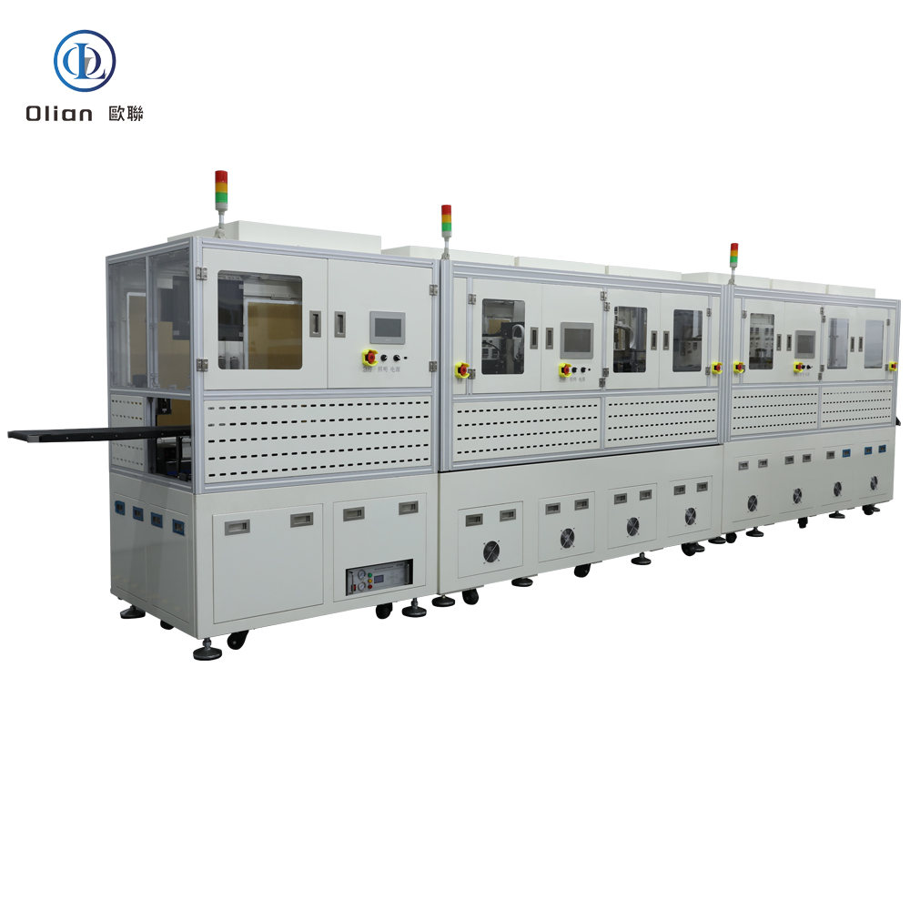
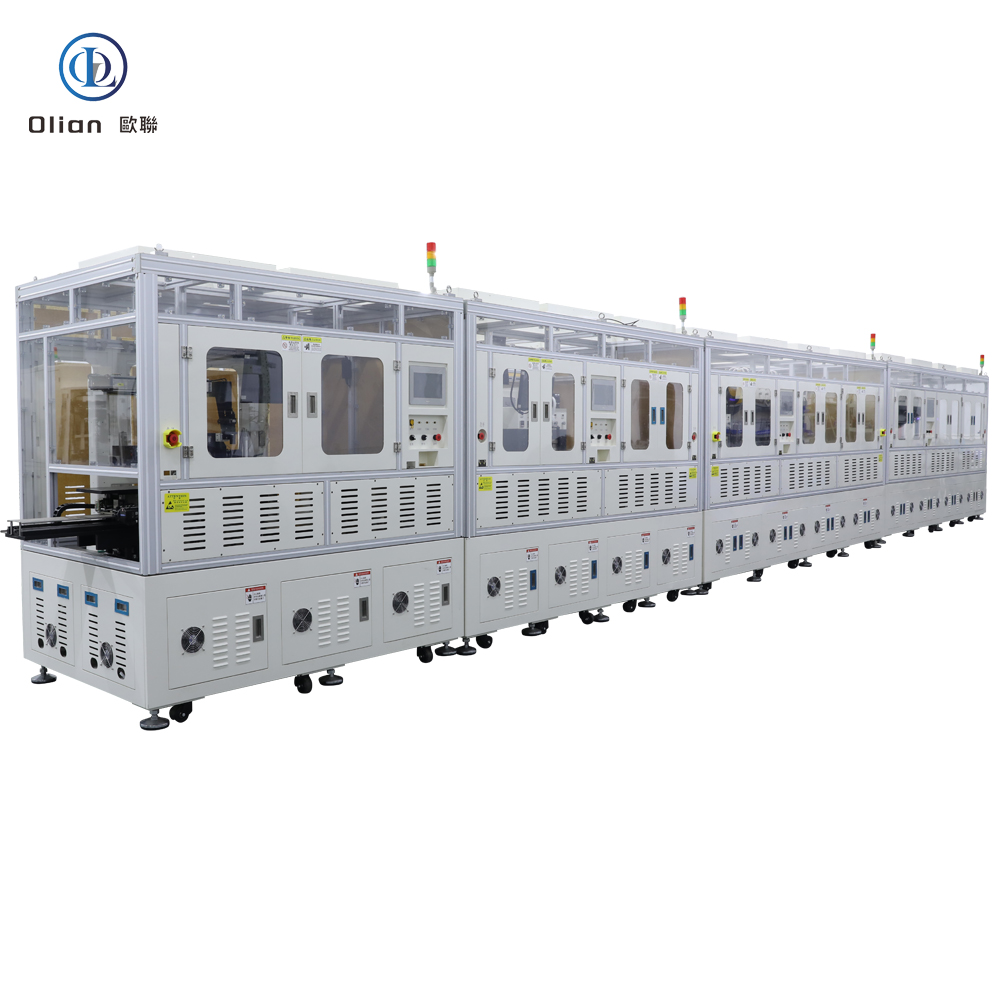
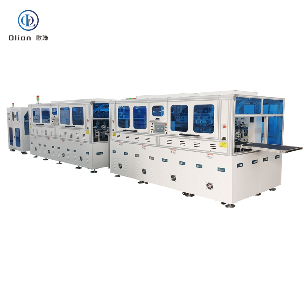
IC CHIP COG COP COF bonderIC CHIP COG COP COF bonderCOG COP COF ACF pre bonding machineIC Chip COG COP COF bonder is the micron-level heart of every modern display factory. It decides whether a driver IC sits directly on glass (COG), on a foldable plastic film (COP), or on a continuous copper-clad tape (COF)COG COP COF ACF pre bonding machineCOF ACF bonding machineIC Chip COG COP COF bonderlIC Chip COG COP COF bonderIC Chip COG COP COF bonderfully automatic FOG bonding machinefully automatic ACF COG COP COF FOG FOB FOF TFOG TFOF OLB TAB Bonding Machine
1. From Silicon to System: Why the Bonder Matters
After wafer test (CP) and bumping (BP), the bare die is still a fragile sliver of silicon. The bonder is the first machine that turns it into a usable electronic component:
COG → glass substrate = razor-thin phone bezel
COP → plastic substrate = foldable OLED
COF → continuous reel = 100-inch TV source driver
The same granite base, voice-coil actuator, and 12 MP vision system can switch between COG, COP, and COF in < 15 s by swapping the temperature/force recipe and the jig.
2. Physics Common to All Three Flavours
Gold or Copper Bumps (5–25 µm high, 20–80 µm pitch) are plated on the IC during BP.
ACF (25–45 µm) is laminated onto the substrate at 80 °C, 0.2 MPa.
Vision Alignment within ±1 µm @ 3σ using dual CMOS cameras and AI edge detection.
Pulse Heat & Pressure:
COG: 180–220 °C, 1.0–1.5 MPa, 1.5 s
COP: 140–180 °C, 0.6–1.0 MPa, 1.5 s (low temp for PET)
COF: 180–220 °C, 1.0–1.5 MPa, 2.0 s (longer for reel index)
Cool Under Load to < 60 °C while maintaining pressure, locking conductive particles.
In-Situ Kelvin Test < 30 mΩ per bump; > 30 mΩ triggers automatic rework.
3. COG (Chip-On-Glass) – The Classic Slim-Bezel Enabler
Substrate: ITO glass (0.3–1.1 mm)
Die Size: 0.5 × 0.5 mm to 15 × 15 mm
Head Force: 10–100 kg
Key Pain Point: Glass thermal expansion mismatch → head must cancel its own weight to 0.1 g resolution
Cold-Laser Clean: Femtosecond laser removes oxide at 25 °C, enabling 120 °C PET bonds.
AI Yield Predictor: Neural networks forecast particle-trap probability, pushing yield to 99.9 %.
Servo-Hydraulic Hybrid: 80 kg force for 100″ TV glass while maintaining 1 µm accuracy.
Roll-to-Roll COF: Reel-fed driver and touch tails bonded at 3,000 UPH.
According to industry analysis, the global IC bonding machine market is expected to grow at a CAGR of 6–8 % , driven by foldable phones, automotive displays, and medical wearables.
.
10. Daily Maintenance Across All Modes
Clean DLC head with IPA every 200 cycles to prevent ACF build-up.
Verify thermocouple vs dry-block weekly; drift > 0.3 °C triggers replacement.
IC Chip COG COP COF bonder, COG bonding machine, COP bonding machine, COF IC bonder, display driver IC bonding, pulse heat COG bonder, low-temp COP bonding machine, reel-fed COF bonder, 1 micron placement accuracy, 200 °C bonding temperature, 1 MPa bonding pressure, vertical conduction horizontal insulation, lead-free IC bonding, ROHS compliant bonding, foldable phone IC bonding, 8-K TV COF bonding, automotive display IC bonding, medical device IC bonding, AI vision IC bonder, IoT IC bonding machine, China IC bonding machine, automatic IC bonder, IC bonding accuracy 1 micron, IC bonding temperature 220 C, IC bonding force 1 MPa, gold bump bonding, copper bump bonding, flip-chip bonding, COG vs COP vs COF, multi-mode IC bonder.
12. Conclusion
Whether you are bonding a 0.3 mm phone driver (COG), a foldable touch sensor (COP), or a 100-inch TV source driver (COF), the modern IC Chip COG COP COF bonder shares one granite spine, one AI brain, and one pulse-heat heart. By mastering sub-micron alignment, single-degree thermal control, and real-time force feedback, these platforms deliver 99.9 % yield and full Industry 4.0 traceability—future-proofing your process.
A flex cable bonding machine—often marketed as FPC bonding machine, flex bonder, or ACF flex welder—is the precision heart that joins a flexible printed circuit (FPC) or flexible flat cable (FFC) to glass, plastic, metal, or another flex, using anisotropic conductive film (ACF) and pulse-heat or constant temperature pressure. Every smartphone OLED, curved automotive cluster, 8-K TV, and disposable medical catheter you touch has passed through such a bonder. The machine aligns copper traces within ±1 µm, ramps temperature 200 °C/s, and forms thousands of vertical contacts in under three seconds—all while keeping lateral isolation > 1 GΩ. This guide explains physics, hardware, software, specs, applications, market trends, and maintenance for “flex cable bonding machine”, “flex bonder”, “ACF flex bonding equipment”, “FPC bonding machine”, “flex cable repair machine”, and every high-value permutation.
A flex cable bonding machine is a servo-driven, vision-guided, pulse-heat press that laminates anisotropic conductive film onto a substrate, then bonds a flexible printed circuit (FPC) or flexible flat cable (FFC) to that substrate with micron-level accuracy. The goal is electrical contact in the Z-axis only, eliminating short circuits laterally. The same platform reworks defective panels by removing the old ACF and rebonding a new tail, saving TV panel or phone OLED. Modern bonders achieve ±1 µm alignment, ±0.5 °C temperature stability, and 0.01 MPa force resolution on substrates as thin as 25 µm and as large as 100-inch TVs.
2. Why Flex Cable Bonding Surges
Rigid PCBs cannot fold; connectors add height and cost; solder joints fatigue. Flex cables absorb thermal expansion, survive 200,000 bend cycles at 0.2 mm radius, and hide behind 0.9 mm bezels. Automotive clusters demand vibration resistance from −40 °C to +105 °C; medical catheters require transparent, sterilizable PET that survives autoclave steam. Flex cable bonding solves these pain points while enabling repair: a defective tail is removed and rebonded without scrapping the entire assembly.
3. Step-by-Step Working Principle (Generic ACF Flow)
Surface Preparation: Both flex and target (glass, PCB, plastic, or second flex) are cleaned with ionized air and IPA to remove dust and oxide.
ACF Lamination: Precision cutter feeds 1–3 mm ACF strip; heated roller (80 °C, 0.2 MPa) tacks film to the substrate.
Vision Alignment: Dual 12 MP cameras capture fiducials on flex and substrate; AI algorithm calculates offset in X, Y, θ, and scale.
Pre-Bond: Head descends at 60 °C and 0.1 MPa to tack the flex; system verifies pad-to-pad overlap ≥ 98 %.
Pulse Heat Bond: Titanium head ramps to 140–220 °C in 1.5 s; pressure rises to 0.6–1.5 MPa; conductive particles deform and capture.
Cool Under Load: Water-cooled block drops temperature below 60 °C while pressure holds, preventing particle relaxation.
Fold Test (Optional): Mandrel folds tail 180° with 0.2 mm radius; vision checks for trace cracking or coverlay whitening.
4. Core Hardware That Determines Performance
Bonding Head: Titanium alloy, diamond-lapped to 0.3 µm flatness, DLC-coated for anti-stick, lasts 300,000 cycles. Pulse Heater: 800 W cartridge, embedded K-type thermocouple, ramp 200 °C/s, overshoot < 0.5 °C. Force Actuator: Voice-coil or servo motor, 24-bit encoder, 0.1 N resolution, 2 ms response; active gravity cancellation for 25 µm glass. Vision System: 12 MP global-shutter CMOS, telecentric lens, coaxial + side LED, sub-pixel edge detection repeatable to 0.2 µm. Motion Stage: Cross-roller bearings, 0.05 µm linear encoder, servo feedback at 20 kHz, granite base with passive vibration isolation. ACF Feed Unit: Stepper-driven, tungsten-steel cutter, anti-static vacuum, waste take-up spool, splice sensor for uninterrupted production.
5. Software & Industry 4.0 Integration
Real-time Linux kernel guarantees < 1 ms jitter; PID temperature loop updated at 10 kHz. Recipe manager encrypts parameters—temperature, pressure, time, ramp rate—per product QR code. AI vision self-learns new pad patterns from vendors, reducing setup time 70 %. MES interface via OPC-UA uploads cycle data, resistance values, and images for full traceability. Cloud dashboard predicts heater degradation and schedules maintenance before scrap occurs.
Cold-Laser Assist: Femtosecond laser pre-cleans ITO at 25 °C, enabling 120 °C low-temp bonds for flexible OLED.
AI Predictive Yield: Neural networks forecast particle-trap probability per bump, pushing yield to 99.9 %.
Servo-Hydraulic Hybrid: 80 kg force for 100″ TV glass while maintaining 1 µm accuracy.
Roll-to-Roll Bonding: Reel-fed driver and touch tails bonded on-the-fly at 3,000 UPH.
According to industry analysis, the global flex cable bonding machine market is experiencing steady growth with a CAGR of 5–8 %, driven by foldable phones, automotive displays, and medical wearables. Asia-Pacific dominates production and consumption, with China hosting the largest supplier base
A flex cable bonding machine is no longer a niche press—it is the universal gateway between floppy copper and rigid glass, plastic, or another flex. By mastering sub-micron alignment, single-degree thermal control, and real-time force feedback, the latest flex bonders deliver sub-3-second cycles with 99.9 % yield and full Industry 4.0 traceability. Whether you are a display OEM chasing 0.9 mm bezels, an automotive Tier-1 qualifying 100-inch curved clusters, or a medical start-up prototyping transparent patches, investing in an AI-enhanced, IoT-connected flex cable bonding platform future-proofs your process.
Modern displays, sensors, and wearables are born on the factory floor through a family of “X-on-Y” bonds. Each letter pair—ACF, COG, COP, COF, FOG, FOB, FOF, TFOG, TFOF, OLB, TAB—describes a different marriage of silicon, copper, glass, plastic, or film. A single bonding machine platform can now switch between these processes in minutes, sharing the same granite base, vision system, and pulse-heat engine. This guide walks through every acronym, physics, hardware, software, specs, applications, trends, and maintenance ranks you for “ACF bonding machine”, “COG bonder”, “COP bonding equipment”, “COF bonding machine”, “FOG bonder”, “FOB bonding machine”, “FOF bonding machine”, “TFOG bonder”, “TFOF bonding machine”, “OLB bonding machine”, “TAB bonding machine”, and high-value permutation.
Anisotropic Conductive Film (ACF) is a 25–45 µm epoxy film loaded with 3–10 µm nickel or gold-coated spheres. When heat (80–220 °C) and pressure (0.2–1.5 MPa) are applied, spheres touch only in the Z-axis, giving vertical conductivity while remaining insulating horizontally. ACF is laminated first; the specific “X-on-Y” step follows. Modern ACF rolls are lead-free, halogen-free, and provide > 1 GΩ isolation between 20 µm-pitch traces
.
2. From Acronym to Physics: What Each Bond Really Means
COG – Chip-On-Glass: bare driver IC flipped onto ITO glass; 150 °C, 1 MPa, ±1 µm.
COP – Chip-On-Plastic (or Chip-On-PI): IC bonded to polyimide/foldable substrate; low-temp 120 °C version exists for PET.
COF – Chip-On-Film: IC bumped onto continuous reel of copper-clad polyimide; same reel later becomes TAB/COF tail.
FOG – Film-On-Glass: FPC or COF tail bonded to glass; 180 °C, 1 MPa, 2.8 s cycle.
TFOG – Touch-Flex-On-Glass: capacitive-touch sensor tail bonded to cover glass; 160–200 °C, survives 200 k bends.
TFOF – Touch-Flex-On-Film: touch sensor tail to plastic substrate; transparent PET, 120 °C bond.
OLB – Outer Lead Bonding: generic term for bonding the “outer” leads of a TAB/COF tail to glass or PCB; often used interchangeably with FOG/FOB.
TAB – Tape Automated Bonding: historic term for copper leads on a polyimide carrier; today synonymous with COF reels.
3. Shared Hardware Core Across All Variants
A modern multi-mode bonding machine uses the same granite base, 0.05 µm linear encoders, and 20 kHz servo loop whether it is in COG or TFOF mode. The head is titanium, DLC-coated, lapped to 0.3 µm flatness. An 800 W pulse heater ramps 200 °C/s with ±0.5 °C stability. Vision is dual 12 MP CMOS, telecentric, repeatable to 0.2 µm. Force is voice-coil driven, 0.1 N resolution, 2 ms response. ACF is cut by tungsten blades and tacked at 80 °C, 0.2 MPa. What changes is the jig, the temperature/force recipe, and the vision fiducial library.
4. Software & Recipe Management
A single HMI stores 500 encrypted recipes; switching from “COG_8K_120Hz” to “TFOF_PET_Medical” takes 15 s. Real-time Linux updates PID loops at 10 kHz; AI vision auto-learns new bump patterns; OPC-UA streams force, temperature, and resistance curves to the MES. Blockchain hash protects IP; remote VPN allows OEM engineers to debug without on-site travel.
5. Temperature & Pressure Windows per Process
COG/COP/COF: 180–220 °C, 1.0–1.5 MPa, 1.5 s pulse
FOG/FOB: 160–200 °C, 0.8–1.2 MPa, 2.0 s pulse
FOF/TFOF: 140–180 °C, 0.6–1.0 MPa, 1.5 s pulse (thin PET)
TFOG: 160–200 °C, 0.8–1.2 MPa, 2.0 s pulse
OLB/TAB: 180–220 °C, 1.0–1.5 MPa, 2.8 s pulse
All variants share ±0.5 °C temperature stability and ±1 µm placement accuracy.
Whether you are bonding a 0.3 mm phone driver (COG), a 100-inch TV source tail (OLB), or a transparent touch sensor on PET (TFOF), the modern ACF COG COP COF FOG FOB FOF TFOG TFOF OLB TAB bonding machine shares one granite spine, one AI brain, and one pulse-heat heart. Mastering sub-micron alignment, single-degree thermal control, and real-time force feedback, these platforms deliver 99.9 % yield and full Industry 4.0 traceability—future-proofing your process.
A T-FOG bonding machine (Touch-Flex-On-Glass) is the micron-precision link that welds the capacitive-touch sensor tail directly to the cover glass or sensor glass of a display module. In every smartphone, tablet, curved automotive cluster, or wearable OLED you touch today, a T-FOG bonder has aligned ITO or metal-mesh touch pads to copper leads within ±1 µm and created thousands of vertical contacts in under three seconds. This article explains physics, hardware, software, specs, applications, trends, and maintenance for “T-FOG bonding machine”, “Touch-Flex-On-Glass bonder”, “touch sensor ACF bonding”, “capacitive touch flex bonding”, “OLED T-FOG bonding”
T-FOG stands for Touch-Flex-On-Glass. The capacitive touch layer of a modern display is a separate flex circuit (often with its own controller IC) that must be electrically connected to the cover glass or sensor glass. The flex tail carries fine copper traces that fan out to ITO or metal-mesh touch pads on the glass. A T-FOG bonding machine laminates anisotropic conductive film (ACF) onto the glass, aligns the touch-flex pads to the glass pads within micron accuracy, and executes a pulse-heat bond at 160–200 °C and 0.8–1.5 MPa. Conductive particles trapped between copper and ITO form < 30 mΩ contacts vertically while remaining > 1 GΩ isolated horizontally. After the bond, the tail is folded 180° so the controller IC hides behind the glass, shrinking the bezel to under 1 mm.
2. Why T-FOG Still Dominates Touch Modules
COG (Chip-On-Glass) places the touch controller directly on the glass, but large 8-K OLED panels generate too much heat—T-FOG moves the IC onto a flex tail that can dissipate heat and be replaced during repair. Connector solutions add 0.3 mm height and cost $0.50; T-FOG adds 0.03 mm and costs <$0.05. Automotive Tier-1 suppliers prefer T-FOG because it passes AEC-Q100 Grade 0 (−40 °C to +150 °C) without a single connector contact.
3. Step-by-Step Working Principle
Glass Cleaning: Atmospheric plasma removes organics and raises surface energy to > 60 dynes.
ACF Lamination: Precision cutter feeds 1–3 mm ACF strip; heated roller (80 °C, 0.2 MPa) tacks film to glass ITO pads.
Vision Alignment: Dual 12 MP cameras capture fiducials on flex pads and glass ITO; AI algorithm calculates offset in X, Y, θ, and scale.
Pre-Bond: Head descends at 60 °C and 0.1 MPa to tack the flex; system verifies overlap ≥ 98 %.
Pulse Heat Bond: Titanium head ramps to 160–200 °C in 1.5 s; pressure rises to 1.0 MPa; conductive particles deform and capture.
Cool Under Load: Water-cooled block drops temperature below 60 °C while pressure holds, preventing particle relaxation.
Fold Test (Optional): Mandrel folds tail 180° with 0.2 mm radius; vision checks for trace cracking or ITO micro-cracks.
4. Core Hardware That Determines Performance
Bonding Head: Titanium alloy, diamond-lapped to 0.3 µm flatness, DLC-coated for anti-stick, lasts 300,000 cycles. Pulse Heater: 800 W cartridge, embedded K-type thermocouple, ramp 200 °C/s, overshoot < 0.5 °C. Force Actuator: Voice-coil or servo motor, 24-bit encoder, 0.1 N resolution, 2 ms response; active gravity cancellation for 0.4 mm glass. Vision System: 12 MP global-shutter CMOS, telecentric lens, coaxial + side LED, sub-pixel edge detection repeatable to 0.2 µm. Motion Stage: Cross-roller bearings, 0.05 µm linear encoder, servo feedback at 20 kHz, granite base with passive vibration isolation. Flex Feed Unit: Servo-driven picker, anti-static vacuum, soft-tip collet for 25 µm polyimide.
5. Software & Industry 4.0 Integration
Real-time Linux kernel guarantees < 1 ms jitter; PID temperature loop updated at 10 kHz. Recipe manager encrypts parameters—temperature, pressure, time, ramp rate—per product QR code. AI vision self-learns new touch-pad patterns from glass vendors, reducing setup time 70 %. MES interface via OPC-UA uploads cycle data, resistance values, and images for full traceability. Cloud dashboard predicts heater degradation and schedules maintenance before scrap occurs.
6. Technical Specifications Buyers Compare
Glass Size: 1″-120″ diagonal (Gen 2.5 to Gen 8.5), thickness 0.3–1.1 mm.
Flex Size: 10 mm × 5 mm to 150 mm × 50 mm, thickness 25–200 µm, copper 12–35 µm.
Copper-Core ACF: Cu-Ag particles cut material cost 50 % while keeping < 20 mΩ contact resistance. Cold-Laser Fold Assist: Femtosecond laser pre-scores the coverlay, enabling 50 µm bend radius with zero trace damage. Servo-Hydraulic Hybrid: Delivers 80 kg force on 100″ TV glass while keeping 1 µm position accuracy. Dual-Head T-FOG: Parallel bonding of touch and source tails doubles throughput without extra floor space. AI-Driven Calibration: Neural networks auto-optimize temperature profiles for each glass type, pushing yield to 99.9 %.
10. Daily Maintenance for 99 % Uptime
Clean DLC head with lint-free wipe and IPA every 200 cycles to prevent ACF build-up.
Inspect vacuum collet for wear; replace if pick accuracy drops 5 µm.
Verify thermocouple vs dry-block calibrator weekly; drift > 0.3 °C triggers replacement.
Store ACF rolls sealed at −10 °C and 30 % RH; 4 h thaw under laminar flow prevents moisture bubbles.
Update AI vision model monthly; new touch-pad patterns from glass vendors are auto-learned.
Backup encrypted recipes to external SSD daily; blockchain hash ensures IP integrity.
11. Conclusion
A T-FOG bonding machine is no longer a niche display tool—it is the critical gateway between microscopic touch-sensor pads and macroscopic glass signals. By mastering sub-micron alignment, single-degree thermal control, and real-time force feedback, the latest T-FOG bonders deliver sub-3-second cycles with 99.9 % yield and full Industry 4.0 traceability. Whether you are a display OEM chasing 0.9 mm bezels, an automotive Tier-1 qualifying 100-inch curved clusters, or a medical start-up prototyping transparent patches, investing in an AI-enhanced, IoT-connected T-FOG bonding platform future-proofs your process.