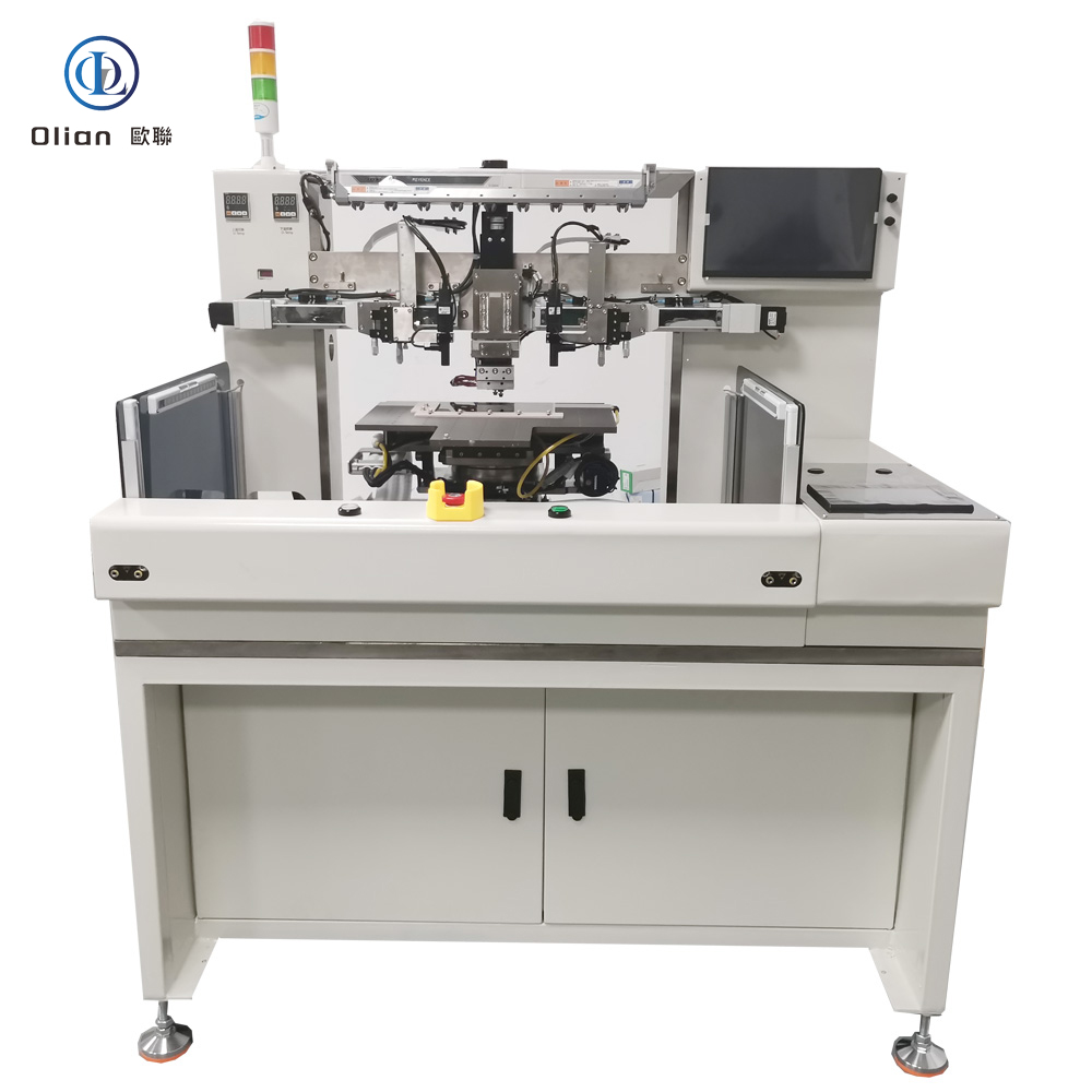
OL-CBQ17 – 17-Inch Semi-Automatic IC Removal Machine
Precision Thermal Decomposition System for Safe and Efficient COG/ IC Recovery
The OL-CBQ17 by Olian Automatic Equipment Co., Ltd. is a semi-automatic IC removal machine designed for the safe, controlled detachment of COG (Chip-on-Glass) integrated circuits from LCD panels up to 17 inches. It uses localized heating and vacuum-assisted lift-off to recover defective or obsolete ICs—minimizing damage to the underlying glass substrate and enabling cost-effective rework or recycling.
This system is ideal for display module repair centers, R&D labs, and pilot production lines where yield recovery and component reuse are priorities.
Controlled Thermal Removal Process
The operator places the LCD panel on the worktable and secures it using a Φ24 mm vacuum button. They then position the custom hot press head directly over the target IC. Using a live monitor feed (with optional magnification), they align the head precisely.
After confirming alignment, the operator presses both dual-hand start buttons—a key safety feature that prevents accidental activation. The press head then descends and heats the IC area to a preset temperature (up to 400°C). Once the ACF (Anisotropic Conductive Film) softens, a gentle upward vacuum pulse or mechanical lift detaches the chip cleanly.
The entire cycle takes less than 10 seconds per IC, ensuring high throughput without thermal stress on surrounding components.
Optical Alignment and Vision Support
The machine supports 1x or 2x optical magnification via interchangeable lenses:
1x lens: Field of view = 6.4 mm × 4.8 mm
2x lens: Field of view = 3.2 mm × 2.4 mm
This allows operators to clearly view fine-pitch alignment marks during setup—critical for narrow-gap COG ICs commonly used in modern displays.
ESD-Safe and Operator-Friendly Design
The OL-CBQ17 is built with full ESD protection:
All contact surfaces use anti-static materials
Panel surface static voltage remains < ±100 V during operation
Static dissipates from 1000 V to 100 V within 4 seconds
ESD wrist strap sockets are provided at all handling points
Machine grounding impedance is ≤ 5 Ω
These features protect sensitive display components from electrostatic discharge damage.
Safety and Control Features
The machine includes multiple safety layers:
EMO (Emergency Stop): Immediately cuts power to all motion units. Servo energy is disabled, allowing manual movement of axes if needed.
Machine Interlock: Triggers a buzzer alarm and on-screen warning if errors occur.
Hazard Labels: Clearly mark high-risk zones (e.g., hot surfaces, pinch points).
Three-Color Signal Tower: Shows real-time status—green (ready), yellow (running), red (fault).
Control is managed via a PLC system and a color touchscreen interface, enabling easy parameter setup and monitoring.
User Access Levels and Security
The system supports two user levels:
Operator Level: No password required. Can run cycles and switch product types.
Engineer Level: Password-protected (non-modifiable). Allows full parameter editing and calibration.
This ensures process consistency while preventing unauthorized changes.
Support, Training, and Warranty
Olian provides one Chinese-language operation manual. On-site training lasts one day and covers:
Machine installation and calibration
Operation, parameter setup, and alignment
Common fault diagnosis and resolution
Replacement of wear parts
Training duration can be adjusted by mutual agreement.
The machine carries a 12-month warranty under normal use. Consumable parts (e.g., heating elements, press heads) are excluded. Damage from misuse or force majeure is not covered. During the warranty period, if remote support fails, an engineer will arrive on-site within 72 hours. Lifetime technical support is available beyond the warranty term.
🔍 SEO Keywords
IC removal machine,17 inch IC removal machine, OL-CBQ17 Olian, semi-automatic COG IC removal machine, COF chip recovery equipment, LCD IC rework system, 400°C thermal decompression machine, ESD-safe IC detachment tool, dual-hand safety start IC remover, PLC-controlled COG rework machine, 2x magnification IC alignment system, China-made IC remover for export, vacuum-assisted IC lift-off machine, Olian OL-CBQ17 technical specs, reliable IC removal machine with 1-year warranty, Shenzhen COG rework equipment, anti-static IC disassembly work platform, touch panel IC recovery system, <10s tact time IC remover, engineer-level password protected bonder, industrial LCD repair machine with EMO stop.
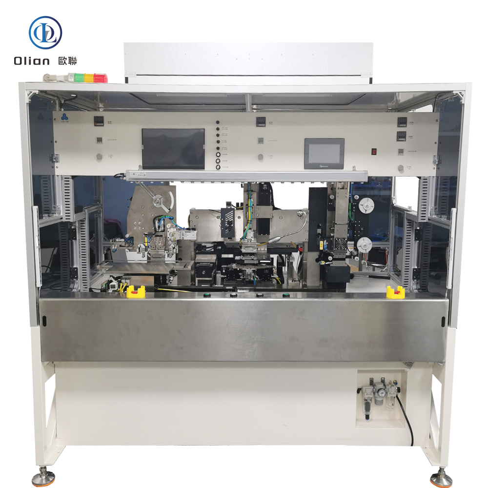
High-Speed Precision Bonder for Multi-Segment Flexible Circuit Assembly
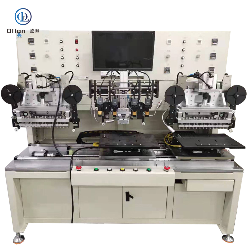
The OL-CRW017-4 by Olian Automatic Equipment Co., Ltd. is a high-performance automatic bonding machine engineered for precise thermal compression of COF (Chip-on-Film) to FPC (Flexible Printed Circuit) modules up to 17 inches. Featuring four high-resolution cameras and full A+P+M (Alignment + Pre-press + Main-press) functionality, it delivers consistent, high-yield bonding for demanding display and electronics manufacturing.
This system is ideal for mass production of driver boards, touch modules, and automotive displays where multi-point COF-to-FPC connections require micron-level accuracy and process repeatability.
Quad-Camera Vision System for Multi-Axis Alignment
Equipped with four independent cameras, the OL-CRW017-4 enables simultaneous alignment at multiple bonding zones. Each camera provides real-time video feed with adjustable magnification and coaxial LED lighting—ensuring clear visibility of alignment marks even on dark or reflective surfaces.
Operators perform initial rough placement manually. Fine alignment is then verified visually via monitors. Once alignment is confirmed as “OK,” the operator initiates the cycle using a dual-hand start mechanism—a critical safety feature that prevents accidental activation during setup.
Three-Stage Automated Bonding: A + P + M
The machine executes a complete three-stage bonding sequence:
Alignment (A): Visual verification of COF and FPC mark registration using quad-camera system.
Pre-press (P): Low-force temporary bonding stabilizes the flex circuit before final cure.
Main-press (M): Full heat and pressure activate the ACF (Anisotropic Conductive Film), forming reliable electrical and mechanical joints.
Temperature is adjustable from room temperature to 400°C, with press head surface uniformity held within ±5°C. Bonding time ranges from 0.1 to 99.9 seconds. Force output is precisely regulated to suit delicate flex materials—minimizing risk of damage.
Standard press heads are made of high-wear tungsten steel. Custom dimensions are available for specialized applications.
Semi-Automatic Workflow with Manual Loading
The OL-CRW017-4 uses a manual loading/unloading approach for maximum flexibility. Operators place the FPC on the worktable and secure it via vacuum. They then position the COF(s) and align them visually. After bonding, they remove the finished module and repeat.
All operations occur from a single front position—enhancing ergonomics and reducing cycle time. The platform includes dense vacuum channels to hold thin FPCs flat during bonding.
Control Interface and Safety Features
The machine includes essential manual controls:
Start/Stop buttons
Emergency Stop (EMO)
Main power switch
Illumination power switch
A three-color signal tower (red/yellow/green) provides instant status feedback: ready, running, or fault. These physical controls ensure reliability in industrial environments—even without complex software interfaces.
Support, Training, and Warranty
Olian provides one Chinese-language operation manual. On-site training lasts one day and covers:
Machine installation and calibration
Operation, parameter setup, and alignment
Common fault diagnosis and resolution
Replacement of wear parts
Training duration can be adjusted by mutual agreement.
The machine carries a 12-month warranty under normal operating conditions. Consumable parts and damage from misuse or force majeure are excluded. During the warranty period, if remote troubleshooting fails, an engineer will arrive on-site within 72 hours. Lifetime technical support is available beyond the warranty term.
🔍 SEO Keywords
COG bonding machine, COP Bonding machine, COF bonding Machine, COG bonder, ACF bonder, ACF bonding Machine, IC COF pre bonding and main bonding machine, 17 inch COF to FPC bonding machine, OL-CRW017-4 Olian, quad-camera FOG Bonding machine, automatic COF-FPC bonder with A+P+M, 400°C hot press bonding equipment, ±5°C uniformity COF hot press machine, four-camera alignment FPC bonder, high-precision COF to flexible PCB machine, Olian OL-CRW017-4 technical specs, semi-automatic COF bonding system for 17 inch panel, China-made COF-FPC bonding machine for export, dual-hand safety start FOG machine, reliable COF rework equipment , servo-controlled FPC bonding platform, industrial COF assembly machine with vacuum stage, Shenzhen Olian automatic bonder with EMO stop, COF to FPC bonder for automotive display, FPC driver board bonding equipment, multi-zone COF bonding machine with manual loading, touch module COF bonding system.
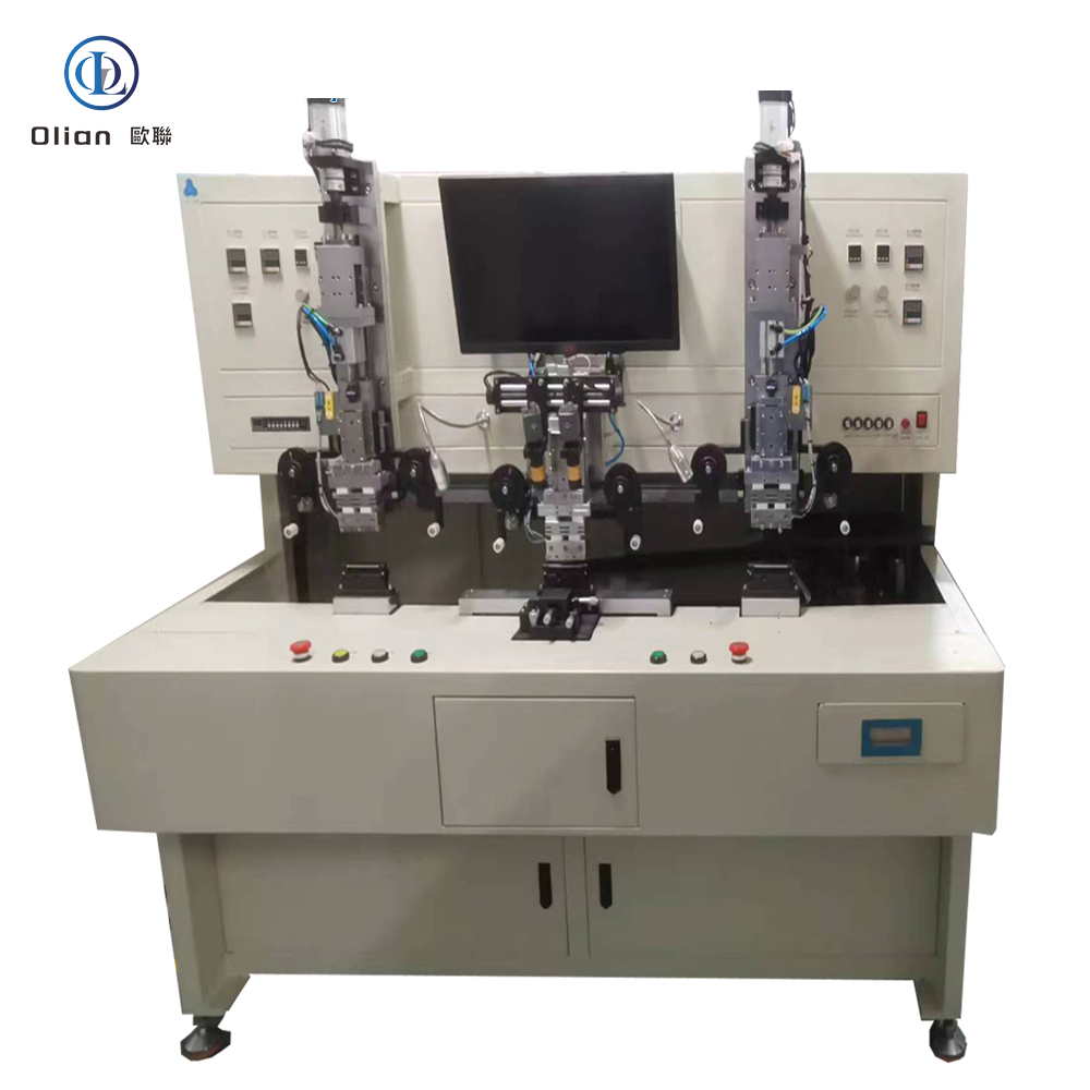
High-Precision Rework System for Defective COG and COF Bonds on Large LCD Panels
High-Precision Rework System for Defective COG and COF Bonds on Large LCD Panels
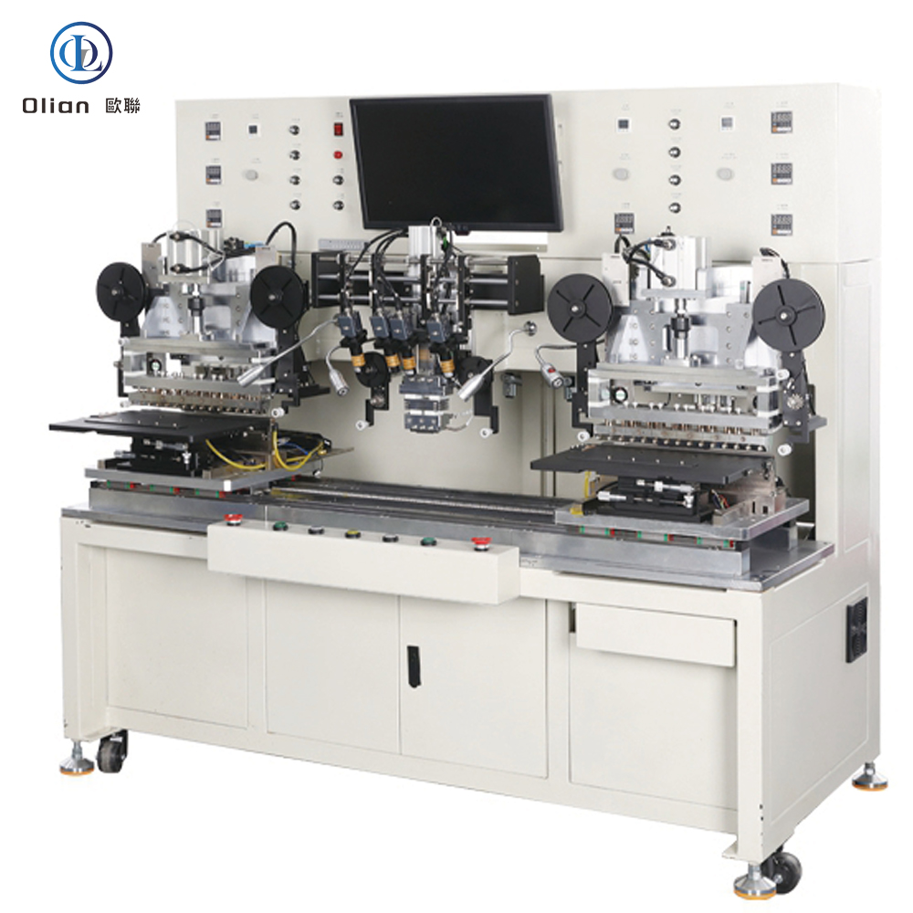
The OL-CRW017-2 by Olian Automatic Equipment Co., Ltd. is an advanced automatic repair machine designed for reworking defective COG (Chip-on-Glass) and COF (Chip-on-Film) bonds on display modules up to 17 inches. Equipped with two high-resolution cameras and supporting A+P+M (Alignment + Pre-press + Main-press) functionality, it enables precise, repeatable thermal re-bonding without damaging surrounding components.
This system is ideal for display module manufacturers, quality control centers, and repair lines where yield recovery and process consistency are critical. It handles both COG ICs and COF flex circuits—making it a versatile solution for modern LCD and touch panel production.
Dual-Camera Vision System for Accurate Alignment
The machine features two independent camera channels, each with adjustable magnification and coaxial LED lighting. Operators use live video feeds to align bonding marks before repair. The dual-view setup allows simultaneous inspection of chip and pad alignment from optimal angles—reducing parallax error and improving rework success rates.
All alignment is performed manually via intuitive controls. Once alignment is confirmed as “OK,” the operator initiates the cycle using a dual-hand start mechanism—a key safety feature that prevents accidental activation.
Three-Stage Repair Process: A + P + M
The OL-CRW017-2 executes a complete three-stage thermal rework sequence:
Alignment (A): Visual confirmation of mark-to-mark registration using dual cameras.
Pre-press (P): A low-force, low-temperature press temporarily fixes the chip or COF in place.
Main-press (M): Full heat and pressure are applied to reflow the ACF (Anisotropic Conductive Film) and form a reliable electrical bond.
Temperature is adjustable from room temperature to 400°C, with surface uniformity maintained within ±5°C across the press head. Bonding time ranges from 0.1 to 99.9 seconds. Force output is precisely controlled to match material sensitivity—preventing glass cracking or flex damage.
Standard press heads are made of wear-resistant tungsten steel. Custom sizes are available upon request.
Safety and Operational Reliability
The machine includes multiple safety layers:
EMO (Emergency Stop): Cuts power to all servos instantly. Motion units can then be moved manually.
Machine Interlock: Triggers audible alarm (buzzer) and on-screen warning if errors occur.
Hazard Labels: Clear stickers mark high-risk zones (e.g., hot surfaces, pinch points).
Three-Color Signal Tower: Shows real-time status—green (ready), yellow (running), red (fault).
These features ensure safe operation in busy production environments.
Mechanical and Environmental Requirements
The system supports panels up to 17 inches with standard thicknesses used in industrial and consumer displays. It requires a clean, static-controlled workspace with stable temperature and humidity. Compressed air must be clean, dry, and supplied at 0.4–0.7 MPa. Power input is single-phase AC 220V ±10%.
The machine frame is robust and finished in industrial-grade coating. All moving parts use precision linear guides and servo-driven actuators for smooth, repeatable motion.
Support, Training, and Warranty
Olian provides one Chinese-language operation manual. On-site training lasts one day and covers:
Machine installation and calibration
Operation, parameter setup, and alignment
Common fault diagnosis and resolution
Replacement of consumable and wear parts
Training duration can be adjusted by mutual agreement.
The machine comes with a 12-month warranty under normal use. Damage caused by misuse, improper environment, or force majeure is excluded. During the warranty period, if remote support fails, an engineer will arrive on-site within 72 hours. Lifetime technical support is available beyond the warranty term.
🔍 SEO Keywords
ACF attaching machine, COG COF pre bonding machine, COF COF COP main bonding machine, ACF COG COF COP all in one machine, 17 inch COG COF repair machine, OL-CRW017-2 Olian, automatic FOG rework machine with dual camera, A+P+M bonding rework system, COG COF bonding reparing machine, 400°C rework hot press machine, ±5°C uniformity repair bonder, dual-camera alignment FOG machine, LCD COF rework equipment, automatic COG re-bonding machine, Olian OL-CRW017-2 technical specs, EMO emergency stop COG repair system, three-color signal tower cOG repairing machine, China-made COG COF rework machine for export, servo-controlled cOG repair platform, reliable COG rework machine with 1-year warranty, industrial display rework station, manual alignment with dual-hand safety start, COG COF rework machine for 17 inch LCD panel, Shenzhen Olian automatic repair machine.
Integrated Thermal Compression Platform for Both FOG and FOB Processes with Sequential Rework Capability
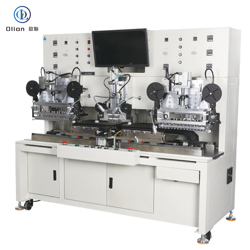
The OL-FF-173 by Olian Automatic Equipment Co., Ltd. is a versatile semi-automatic bonding machine designed for medium-sized display modules up to 17.3 inches. It uniquely supports both FOG (Film-on-Glass) and FOB (Film-on-Board) processes—including pre-bonding, main bonding, and rework functions—all within a single integrated platform. This makes it ideal for pilot lines, small-batch production, or repair stations handling mixed product types.
The system features a single-side, multi-segment architecture that can process up to 6 FPCs or 6 PCBs along one edge of a panel in sequence. Operators can configure the machine to run FOG only, FOB only, or FOG followed immediately by FOB—without changing hardware. If both are enabled, the machine automatically completes all FOG steps first, then proceeds to FOB bonding on the same unit.
Dual-Mode Workflow: FOG and FOB in One Cycle
For FOG mode, the operator places the LCD panel on the glass worktable and activates vacuum suction. They then position the FPC(s) on the FPC stage and perform rough alignment. Using a live monitor feed, they fine-tune alignment visually. After pressing both start buttons, the pre-press head descends to temporarily bond the first segment. The platform then shifts automatically to the next position. This repeats until all pre-press zones are complete. Finally, the platform moves to the main bonding station. The main press head applies full heat and pressure to cure all segments at once.
If FOB mode is also enabled, the machine returns to the FOG pre-press station—but now treats the bonded module as a “panel” for FOB processing. The operator places a PCB on the worktable, aligns it with the existing FPC leads, and initiates another bonding cycle. This seamless transition eliminates manual transfer between machines and reduces handling damage.
All loading, alignment, and unloading occur from the same front position, improving ergonomics and workflow consistency.
Precision Thermal and Mechanical Performance
Both pre-press and main-press heads operate within a temperature range of room temperature to 400°C, with surface uniformity held to ±5°C—ensuring reliable ACF curing. Bonding time is adjustable from 0.1 to 99.9 seconds.
Force output is independently controlled:
Pre-press: 25 N to 400 N
Main press (FOG): 35 N to 500 N
Standard press head dimensions are:
Pre-press: 55 mm × 1 mm
FOG main press: 55 mm × 1 mm
FOB main press: 55 mm × 2 mm
All heads are made of high-wear-resistant material and can be customized to match specific COF or PCB layouts.
Control, Safety, and Reliability
The machine uses physical controls including Φ24 mm start and vacuum buttons, plus a Φ22 mm emergency stop switch. A three-color signal lamp indicates operational status (ready, running, fault). While the document does not specify PLC or touchscreen use, the process is fully automated once started—minimizing operator error.
Safety is reinforced by the dual-hand start requirement, preventing accidental activation during alignment.
Support, Training, and Warranty
Olian includes one Chinese-language operation manual. On-site training lasts one day and covers installation, parameter setup, common troubleshooting, and replacement of wear parts. Duration can be adjusted by mutual agreement.
The machine carries a 12-month warranty under normal operating conditions. Consumable parts and damage from misuse or force majeure are excluded. During the warranty period, if remote support fails, an engineer will arrive on-site within 72 hours. Lifelong technical support is provided beyond the warranty term.
Ideal Applications
The OL-FF-173 excels in environments requiring flexibility and rework capability—such as:
Display module R&D labs
Small-volume OEM production
Repair centers handling defective FOG/FOB units
Manufacturers of industrial, medical, or automotive displays with mixed FPC/PCB interfaces
Its ability to perform FOG → FOB in one continuous flow significantly reduces cycle time and improves yield compared to using two separate machines.
🔍 SEO Keywords
FOG bonding machine, FOB bonding machine, FOG bonder, FOB bonder, 17.3 inch FOG FOB combo machine, OL-FF-173 Olian, single-side multi-zone FOG bonder, FOB rework bonding equipment, integrated FOG and FOB bonder, 400°C pre-main press bonder, ±5°C uniformity hot press head, sequential COF bonding machine, medium-size display thermal compression system, FOG to FOB inline bonding machine, semi-automatic FOG/FOB rework station, Olian OL-FF-173 technical specs, dual-process FOG FOB bonding machine with vacuum platform, China-made bonding machine for LCD repair, 6-segment FPC bonder, reliable FOG FOB bonder with 1-year warranty, touch panel and driver board bonding system, FOG FOB rework machine for 17.3 inch display, manual alignment bonding machine with dual-hand safety, export-ready FOG FOB bonding machine.
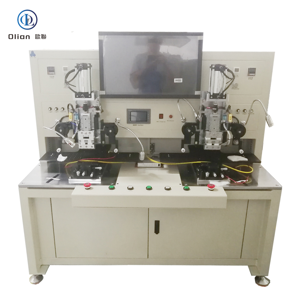
OL-F017 – 17-Inch Dual-Station FOG Bonding Machine
High-Precision Semi-Automatic COF Bonding System for Touch Displays
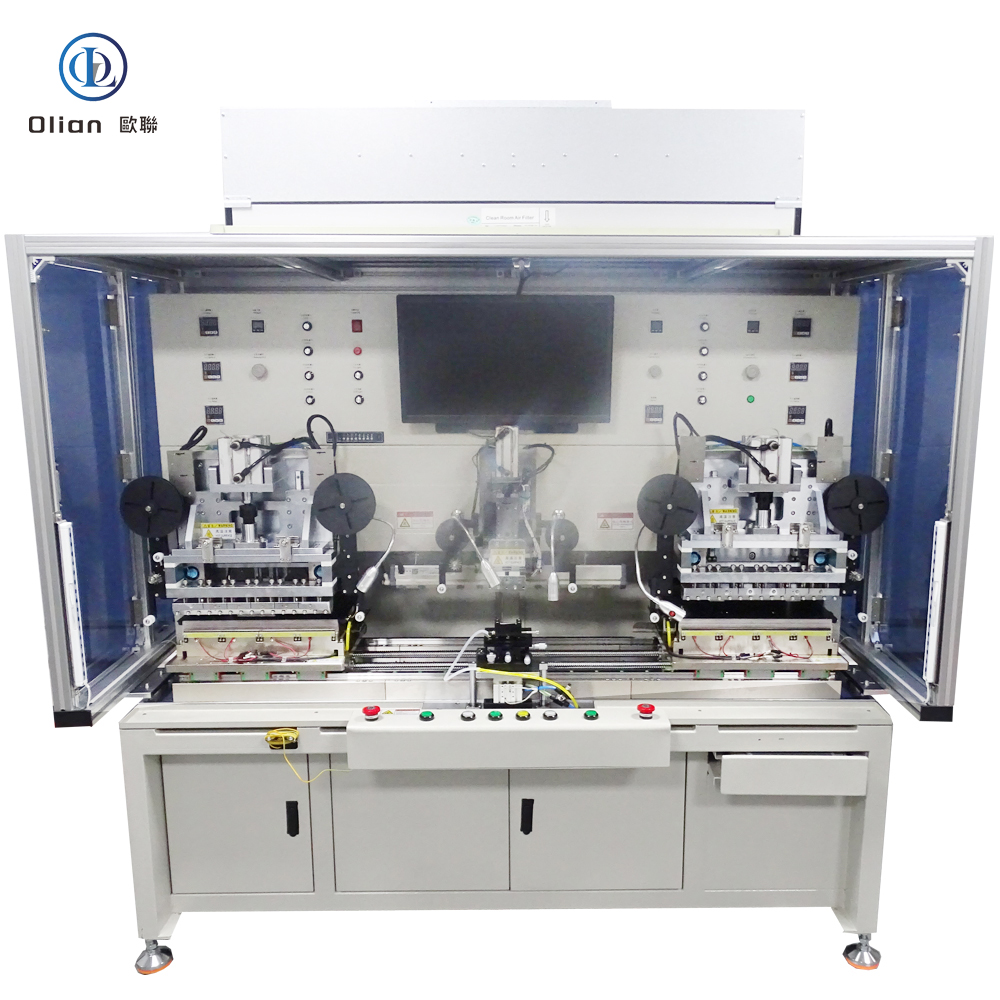
The OL-F017 by Olian Automatic Equipment Co., Ltd. is a high-performance semi-automatic FOG (Film-on-Glass) bonding machine designed specifically for large-format touch panels up to 17 inches. It features a dual-station platform with in-and-out linear motion and lower-side visual alignment, enabling efficient, precise bonding of COF (Chip-on-Film) circuits onto LCD glass edges. This model is optimized for touch panel (TP) manufacturers requiring custom alignment workflows and stable thermal compression.
Unlike top-view alignment systems, the OL-F017 uses a bottom-mounted camera and monitor setup. Operators view alignment marks from below through the transparent glass substrate. This “lower alignment” method reduces parallax error and improves accuracy—especially critical for narrow-pitch COFs used in modern touch displays.
Dual-Station Workflow for Maximum Efficiency
The machine operates with two independent workstations that move linearly between loading and bonding positions. While one station is under compression, the operator can load or unload the other—doubling throughput without extra labor. Both stations share the same bonding head but operate sequentially, ensuring consistent process control.
A single operator handles all steps from one position. They place the LCD panel on the glass platform and activate vacuum hold-down. Then they position the FPC on its dedicated stage. Using the live monitor feed, they manually adjust X/Y/θ alignment until the mark points match. Once confirmed as “OK,” they press both start buttons to begin the cycle.
The platform then moves automatically into the bonding zone. The heated press head descends, applies preset force and time, and completes the main bond. After bonding, the platform returns to the loading position. If enabled, the buffer tape advances once. The operator removes the finished panel and repeats the process.
Precision Bonding Performance
The OL-F017 supports panels from 5 inches (112 × 65 mm) to 17 inches (380 × 240 mm) with thicknesses from 0.2 mm to 2.2 mm. FPC dimensions range from 12 × 12 mm to 60 × 60 mm, with a minimum mark-to-mark distance of 11 mm. The COF-to-glass step height must be at least 0.4 mm to ensure proper contact.
Bonding parameters are fully adjustable:
Temperature: Room temperature to 400°C, with surface uniformity within ±5°C
Time: 0.1 to 99.0 seconds
Force: 25 N to 400 N
The standard FPC press head measures 60 mm × 1.0 mm but can be customized per customer requirements. Heating is fast and stable, using embedded cartridge heaters with real-time feedback.
Vision and Alignment System
The machine includes a 2x optical magnification lens with a 1.9 mm × 1.4 mm field of view. Lighting is provided by a coaxial LED source, eliminating shadows and enhancing mark contrast. The two camera lenses can be spaced from 11 mm to 90 mm apart, accommodating various COF layouts.
This lower-alignment design is ideal for transparent substrates like cover glass or OGS (One-Glass Solution) panels. It avoids interference from upper fixtures and provides a direct view of alignment targets.
Mechanical and Environmental Specifications
The LCD platform measures 550 mm (W) × 320 mm (D). The FPC stage is 120 mm × 60 mm. The entire machine weighs approximately 380 kg and stands 1550 mm tall, with a work height of 860 ± 30 mm. Its footprint is 1550 mm (W) × 960 mm (D).
The frame is finished in industrial beige, while functional parts are chrome-plated or anodized for durability. All surfaces are delivered clean and dust-free. Warning labels are affixed near hot or moving components for safety.
Operation requires a cleanroom environment with temperature between 22°C and 27°C and humidity from 40% to 70% RH. The machine must be used in a dust-controlled, static-safe area to protect sensitive display components.
Buffer Tape and Safety Features
An integrated buffer tape mechanism manages ACF carrier film. It accepts tape with an inner diameter ≥33 mm and outer diameter ≤80 mm. The feed pitch is adjustable from 1 to 20 mm. If the tape fails to advance during operation, the system triggers an audible and visual alarm—preventing missed bonds.
Control is managed via PLC logic, a color touchscreen interface, and physical manual buttons. Emergency stop and dual-hand start functions ensure operator safety. The system also includes status indicators and fault diagnostics.
Support, Training, and Warranty
Olian provides one Chinese-language operation manual. On-site training lasts one day and covers installation, parameter setup, troubleshooting, and replacement of wear parts. Training duration can be adjusted by mutual agreement.
The machine carries a 12-month warranty under normal use. Consumables and damage from misuse or force majeure are excluded. During the warranty period, if remote support fails, an engineer will arrive on-site within 72 hours. Lifelong technical support is available after warranty expiration.
🔍 SEO Keywords (Optimized for Global Search)
FOG bonder,FOG bonding machine,FOG binding machine,17 inch FOG bonding machine, OL-F017 Olian, dual-station FOG bonder, lower alignment COF bonder, touch panel FOG machine, semi-automatic Film-on-Glass equipment, 400°C FOG bonding equipment, ±5°C uniformity hot press, coaxial light vision FOG system, 2x magnification alignment camera, large LCD COF bonding machine, TP customized FOG bonder, in-out platform FOG machine, Olian OL-F017 technical specs, FOG machine for 17 inch touch display, manual alignment FOG bonding machine with PLC control, buffer tape alarm FOG system, China-made FOG bonder for export, dual-operator FOG machine with single loading position, reliable FOG bonding machine with 1-year warranty.
High-Efficiency Thermal Compression System for Multi-Segment COF-to-PCB Bonding
The OL-FOB156L by Olian Automatic Equipment Co., Ltd. is a semi-automatic FOB (Film-on-Board) bonding machine engineered for the precise thermal compression of multiple COF (Chip-on-Film) or FPC (Flexible Printed Circuit) leads onto a single edge of rigid PCBs used in display modules up to 15.6 inches. Designed with a long main press head, this system supports multi-segment sequential bonding, enabling high-reliability electrical connections across extended or densely populated PCB bonding zones—common in automotive displays, industrial control panels, and smart appliance interfaces.
Unlike single-point bonders, the OL-FOB156L allows operators to process up to 10 individual FPCs along one side of a PCB in a single workflow, significantly improving throughput while maintaining consistent bond quality.
FKey Features and Capabilities
The machine operates through a well-defined manual-assisted process..
The operator begins by placing the PCB onto the dedicated worktable and activating vacuum suction via a Φ24 mm button to ensure flatness and stability.
Next, the FPCs are positioned on their respective stage and roughly aligned with the PCB pads. Using a live monitor feed, the operator performs fine visual alignment before initiating the cycle with a dual-hand start mechanism—a critical safety feature that prevents accidental activation.
Once started, the machine automatically executes a pre-press step at the first bonding position using a compact 55 mm × 2 mm tungsten carbide press head.
After completion, the platform shifts horizontally to the next segment, repeating the pre-press until all designated positions are processed.
If the system is configured for automatic alignment (e.g., with optional vision), pre-press may be skipped, proceeding directly to main bonding.
Main bonding station
Following pre-press, the platform moves to the main bonding station,
where two long (200 mm × 2 mm standard) tungsten carbide press heads descend simultaneously.
These heads deliver a precisely controlled force ranging from 55 N to 1000 N,
with temperature maintained between room temperature and 400°C.
The surface temperature uniformity across the press head is guaranteed within ±8°C, ensuring consistent ACF (Anisotropic Conductive Film) curing. Bonding time is fully adjustable from 0.1 to 99.9 seconds.
Both pre-press and main press units utilize pneumatic cylinders with linear guides for smooth vertical.
motion and precision pressure regulators for repeatable force control.
The press heads are made of tungsten steel, offering exceptional wear resistance and surface flatness within ±5 microns. The main press heads also feature push-pull adjustment screws for fine-tuning parallelism relative to the PCB surface.
The PCB platform is constructed from hard anodized magnesium aluminum alloy, providing excellent rigidity and thermal stability. It incorporates a dense array of 1 mm vacuum holes and channels to secure panels firmly during bonding.
Platform flatness is maintained within ±0.008 mm per 100 mm, and it supports four-axis manual adjustment (X, Y, θ, and Z) via micrometer-style knobs with ±3 mm (X/Y/θ) and ±4 mm (Z) travel—enabling precise registration even with panel tolerances.
The machine is designed for single-operator use, with all loading, alignment. and unloading performed.
from the same front position, enhancing ergonomics and workflow efficiency.
Control and Safety
Operation is managed through physical controls: a Φ24 mm start button, a Φ24 mm vacuum switch.
and a Φ22 mm emergency stop.
A three-color signal lamp provides real-time status feedback (ready, running, fault). The system does not include a PLC or touchscreen, prioritizing simplicity and reliability in production environments.
Support and Warranty
Olian includes a Chinese-language operation manual and provides one-day on-site training covering.
installation, parameter setup, routine maintenance, and replacement of consumable parts.
The machine is covered by a 12-month warranty under normal operating conditions.
During the warranty period, if remote troubleshooting fails, Olian guarantees on-site technical support within 72 hours. Lifelong technical assistance is available beyond the warranty term.
Customization and Applications
While the standard main press head measures 200 mm × 2 mm, Olian offers customization to match specific PCB layouts. This model is particularly suited for applications requiring long-edge, multi-chip COF bonding, such as driver boards for large-format LCDs where multiple flex circuits must be reliably connected in sequence.
In summary, the OL-FOB156L delivers a robust, efficient, and operator-friendly solution for medium-to-high volume FOB production—combining precision mechanics, thermal stability, and flexible multi-zone capability in a single platform.
🔍 SEO Keywords for Global Visibility
FOB bonder,FOB bonding machine, FOB binding machine, FOB hot press machine, FOB machine, FOB equipment, FOB machinery,FOB fpc on pcb bonding machine, FOB bond, COF on PCB bonding machine, 15.6 inch FOB bonding machine, OL-FOB156L Olian, long press head COF to PCB bonder, multi-segment FOB bonder, semi-automatic Film-on-Board machine, COF bonding equipment for display modules.400°C FOB bonder, high-force FPC bonding machine 1000N.tungsten carbide press head FOB machine, multi-zone COF bonding system, automotive display FOB bonder.industrial HMI PCB bonding machine, manual FOB bonding machine with vacuum platform.Olian OL-FOB156L technical specifications, FOB machine for 15.6 inch LCD driver board, sequential COF bonding equipment.ACF thermal compression machine, FOB press head with dual-hand safety start, China-made FOB bonder for export, reliable FOB bonding machine with 1-year warranty.
OL-FOG156 Series – 15.6-Inch Single-Side Multi-Zone FOG Bonding Machines
OL-FOG156 Series – 15.6-Inch Single-Side Multi-Zone FOG Bonding Machines
Flexible Thermal Compression Systems for High-Density COF Bonding on LCD Panels
The OL-FOG156 Series by Olian Automatic Equipment Co., Ltd. comprises two variants of semi-automatic single-station FOG (Film-on-Glass) bonding machines, engineered for multi-segment thermal compression of COF (Chip-on-Film) circuits onto one edge of large-format rigid LCD panels up to 15.6 inches.
Both models support sequential pre-bonding and main bonding in a single workflow, with operator-assisted visual alignment via monitor. The key difference lies in the press head length, enabling optimization for either long continuous COF arrays (OL-FOG156L) or shorter, discrete COF segments (OL-FOG156S).
⚠️ Note: These machines assume that ACF has already been applied. They perform thermal compression only, not ACF lamination or automated vision alignment.
🔧 Shared Core Specifications (Both Models)
Feature
Specification
Panel Size
Max: 350 mm × 250 mm (~15.6″) Min: 150 mm × 80 mm (~7″) Thickness: 0.2–2.2 mm
Temperature Range
RT to 400°C (both pre-press & main press)
Press Head Uniformity
≤ ±8°C across surface
Bonding Time
0.1 – 99.9 seconds (programmable)
Pre-Press Force
25 – 400 N
Main Press Force
OL-FOG156L: 55 – 1000 N OL-FOG156S: 25 – 400 N
Max FPCs per Edge
≤10 pcs (OL-FOG156L) ≤ Number of main press heads (OL-FOG156S)
Manual buttons + indicator lights (no PLC/touchscreen)
Safety
Emergency stop, dual-hand start, three-color status lamp
🆚 Key Differences: Long vs. Short Press Head
Parameter
OL-FOG156L (Long Head)
OL-FOG156S (Short Head)
Pre-Press Head Length
55 mm × 1 mm (standard)
55 mm × 1 mm (standard)
Main Press Head Length
200 mm × 2 mm (standard)
220 mm × 1 mm (standard)
Typical Use Case
Bonding long, continuous COF ribbons (e.g., single wide driver IC or multi-chip array spanning >150 mm)
Bonding multiple short, discrete COFs (e.g., 2–10 separate flex circuits along one edge)
Force Capability
Higher main press force (up to 1000 N) for robust bonding of wide areas
Moderate force (up to 400 N), sufficient for standard COF segments
Customization
Both heads customizable per customer layout
💡 Design Insight: Despite the name “short,” the OL-FOG156S actually has a slightly longer nominal main head (220 mm vs. 200 mm), but it is thinner (1 mm vs. 2 mm) and optimized for modular, segmented pressure application—not continuous wide-area bonding.
🖥️ Process Workflow (Identical for Both Models)
Operator places LCD panel on vacuum worktable.
Presses vacuum button to secure panel flatness.
Places COF(s) on FPC stage and performs rough alignment.
Uses monitor display for fine visual alignment.
Presses dual start buttons → machine performs pre-press at first segment.
Platform automatically indexes to next position; repeat until all pre-press zones complete.
Machine moves to main press station; main head descends for final bonding.
After cycle completion, operator removes finished panel and repeats.
This semi-automated multi-zone approach ensures consistent bonding quality across complex edge layouts without full automation cost.
📏 Machine Physical Data (Estimated)
Dimensions: ~1420 mm (W) × 1210 mm (D) × 1912 mm (H)
You bond wide or long COF ribbons (e.g., single 180-mm driver)
You require higher main press force (up to 1000 N)
Choose OL-FOG156S if:
You bond multiple short COFs (e.g., 4–8 separate flexes)
Your process uses modular press heads matched to COF count
Main press force ≤ 400 N is sufficient
🔎 SEO Keywords
FOG BONDER,FOG bonding machine,15.6 inch multi-zone FOG bonder, OL-FOG156L vs OL-FOG156S, long press head COF bonder, short press head FOG bonding machine, single-side multi-segment COF bonding machine, Olian FOG156 series, 400°C FOG bonder for LCD, manual FOG machine with visual alignment, customizable press head FOG system.
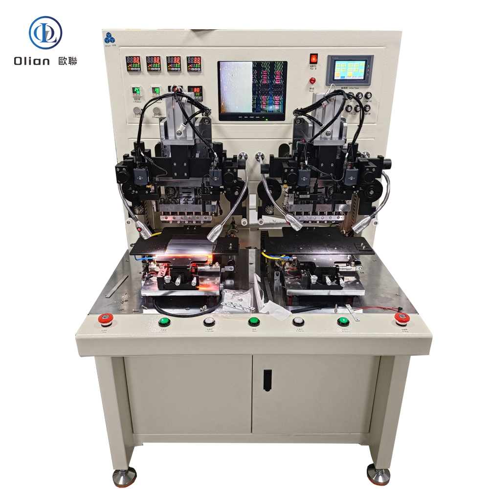
OL-TAB173 – 15.6-Inch Dual-Station Integrated FOG & FOB Bonding Machine,
OL-TAB173 – 15.6-Inch Dual-Station Integrated FOG & FOB Bonding Machine
All-in-One Thermal Compression System for COF (FOG) and COB (FOB) Bonding in a Single Platform
The OL-TAB173 by Olian Automatic Equipment Co., Ltd. is an innovative dual-station integrated bonding machine that combines FOG (Film-on-Glass) and FOB (Film-on-Board) processes in one compact system—left station for FOG, right station for FOB. Designed for panels up to 15.6 inches, it enables seamless production of display modules requiring both COF-to-LCD and COF-to-PCB connections, such as automotive displays, industrial HMIs, and smart appliances.
This integrated approach eliminates the need for separate machines, reduces footprint, minimizes handling, and ensures process consistency between FOG and FOB steps—critical for yield and reliability in high-end applications.
⚠️ Note: This machine assumes that ACF has already been applied to both the LCD panel and PCB. It performs final main bonding only, not ACF lamination or pre-alignment.
🔧 Key Technical Features
✅ Dual-Function Dual-Station Design
Left Station: Dedicated to FOG bonding – attaches COF flex to LCD glass edge
Right Station: Dedicated to FOB bonding – attaches the same (or another) COF tail to a rigid PCB (e.g., driver board)
Both stations operate independently, allowing parallel processing or sequential workflow
Ideal for end-to-end module assembly without intermediate transfer
✅ Bonding Performance
Panel/PCB Compatibility:
Max Size: 350 mm × 250 mm (~15.6″ diagonal)
Thickness: 0.2 – 2.2 mm (glass), 0.8 – 2.0 mm (PCB typical)
COF Specifications:
Width: 12 – 30 mm
Length: 12 – 60 mm
Thickness: 0.02 – 0.2 mm
Bonding Force: Servo-controlled, 20–120 N (repeatability ≤ ±3 N)
Temperature Range: Up to 400°C with uniform heating
Bonding Time: 0.1 – 99.9 seconds (programmable per station)
✅ Control & Operation
Control Unit:
PLC-based logic controller
Color touchscreen HMI (Chinese interface) for parameter setup and monitoring
Operating Modes:
Manual Mode: Full control over each station
Auto Mode: One-button cycle per station after loading
Physical Controls:
Start Button (Φ24 mm)
Vacuum Button (Φ24 mm)
Emergency Stop (Φ22 mm, red mushroom type)
💡 Note: Unlike some FOG-only models (e.g., OL-F0712), this unit does not include vision alignment—it is intended for pre-aligned COF from upstream processes.
📏 Machine Physical Data
Dimensions: Approx. 1420 mm (W) × 1210 mm (D) × 1912 mm (H)
Weight: ~780 kg
Work Height: Platform at 890 ± 30 mm from floor
Power Supply: AC 220V, 50/60 Hz, single-phase
Compressed Air: 0.4–0.7 MPa
Operating Environment:
Cleanroom recommended (ISO Class 8 or better)
Temperature: 22–27°C | Humidity: 40–70% RH
🛠️ Standard Components
Two independent vacuum platforms (left for glass, right for PCB)
Custom hot press heads for FOG and FOB (tooling per customer drawing)
Φ9.5 mm cartridge heaters
K-type thermocouples for temperature feedback
Φ24 mm start and vacuum buttons
Φ22 mm emergency stop switch
National-standard (GB) maintenance toolkit
🛡️ Quality Assurance & Support
Documentation: Includes 1 Chinese-language operation manual
Training: 1-day on-site session covering:
Dual-station workflow setup
Parameter tuning for FOG vs. FOB (different force/temp profiles)
Common fault diagnosis and wear-part replacement
Warranty: 12 months on mechanical and electrical systems under normal use
Exclusions: Consumables, damage from misuse, or force majeure
After-Sales Service:
Lifetime technical support
On-site engineer within 72 hours if remote troubleshooting fails during warranty
🔖 Model Summary
Model: OL-TAB173
Function: Integrated FOG + FOB main bonder in one machine
Layout: Left = FOG (LCD), Right = FOB (PCB)
Panel Size: Up to 15.6 inches
Core Advantage: Single-platform solution for complete COF interconnect chain
Target Applications:
Automotive display modules (LCD + driver board)
Industrial touch panels with integrated control boards
Smart home appliance displays
Medical monitor assemblies
🔎 SEO Keywords (for Global Visibility)
FOG Bonding machine, FOB bonding machine, FOG bonder, FOB bonder, COF bonder ,COF bonding machine,15.6 inch FOG-FOB integrated bonding machine, OL-TAB173 Olian, dual-station COF bonder for LCD and PCB, left FOG right FOB bonder, all-in-one Film-on-Glass and Film-on-Board machine, servo COF bonding system for automotive displays, OL-TAB173 technical datasheet, dual-function bonding equipment for display module assembly, FOG+FOB 2 in 1, high-repeatability COF bonding machine with PLC control. COF repairing machine for laptop, COF repairing machine for notebook,
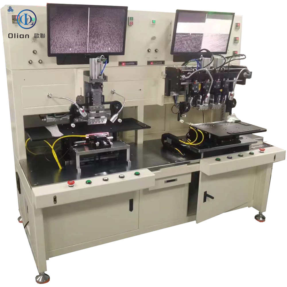
OL-F0712 – 15.6-Inch Dual-Station FOG Bonding Machine with Top & Bottom Vision Alignment
OL-F0712 – 15.6-Inch Dual-Station FOG Bonding Machine
Ultra-High-Precision Thermal Compression System for Front & Rear COF/FOG Bonding on LCD Panels
The OL-F0712 by Olian Automatic Equipment Co., Ltd. is a semi-automatic dual-station FOG (Film-on-Glass) bonding machine engineered for the final thermal compression of COF (Chip-on-Film) flex circuits onto both front and rear edges of large-format rigid LCD panels up to 15.6 inches. What sets it apart is its dual-camera vision system—featuring simultaneous top-view and bottom-view alignment—enabling unparalleled registration accuracy between COF terminals and ITO pads, even on multi-layer, opaque, or high-density interconnect (HDI) panels.
Combined with dual independent workstations, the OL-F0712 delivers both micron-level precision and continuous production throughput, making it ideal for demanding applications in automotive displays, medical imaging, avionics, and premium consumer electronics.
⚠️ Note: This machine assumes that ACF has already been applied to the panel. It performs final main bonding only, not ACF lamination or pre-bonding.
🔍 Key Technical Features
✅ Dual-Vision Alignment System (Top + Bottom)
Camera Configuration:
Top Camera: Views COF from above
Bottom Camera: Images panel pads through glass substrate
Lens Magnification: 2× optical zoom (per camera)
Field of View (FOV): 1.9 mm × 1.4 mm
Lighting: Coaxial LED illumination on both sides for glare-free, shadow-free imaging
Inter-Camera Distance: Adjustable from 12 mm to 90 mm to match various COF pitches
Alignment Method: Operator manually fine-tunes X/Y/θ alignment using live split-screen view until COF and pad patterns are perfectly overlaid
This stereo alignment capability eliminates parallax and layer-shift errors—critical for panels with black matrix, touch sensors, or embedded layers.
✅ Dual-Station Continuous Workflow
Two independent vacuum platforms enable parallel operation:
While Station 1 performs bonding, the operator loads/unloads Station 2
Reduces cycle time by up to 40% compared to single-station machines
Optimized for high-mix, medium-to-high volume production
✅ Bonding Performance
Panel Compatibility:
Max Size: 350 mm × 250 mm (~15.6″ diagonal)
Thickness: 0.2 – 2.2 mm
COF Specifications:
Width: 12 – 30 mm
Length: 12 – 60 mm
Thickness: 0.02 – 0.2 mm
Bonding Force: Servo-controlled, 20–120 N (repeatability ≤ ±3 N)
Temperature Range: Up to 400°C with surface uniformity ≤ ±2°C
Industrial HMIs with high-reliability requirements
High-end laptops and tablets with narrow bezels
🔎 SEO Keywords (for Global Visibility)
FOG bonding machine,FOB bonding machine, 15.6 inch dual-vision FOG bonding machine, OL-F0712 Olian, top and bottom alignment fog bonding machine, dual-camera FOG bonder for LCD, front and rear COF bonding equipment, 2x magnification stereo vision COF aligner, coaxial LED top-bottom FOG machine, high-precision Film-on-Glass system for automotive displays, OL-F0712 technical datasheet, dual-station COF bonding machine with buffer tape alarm.
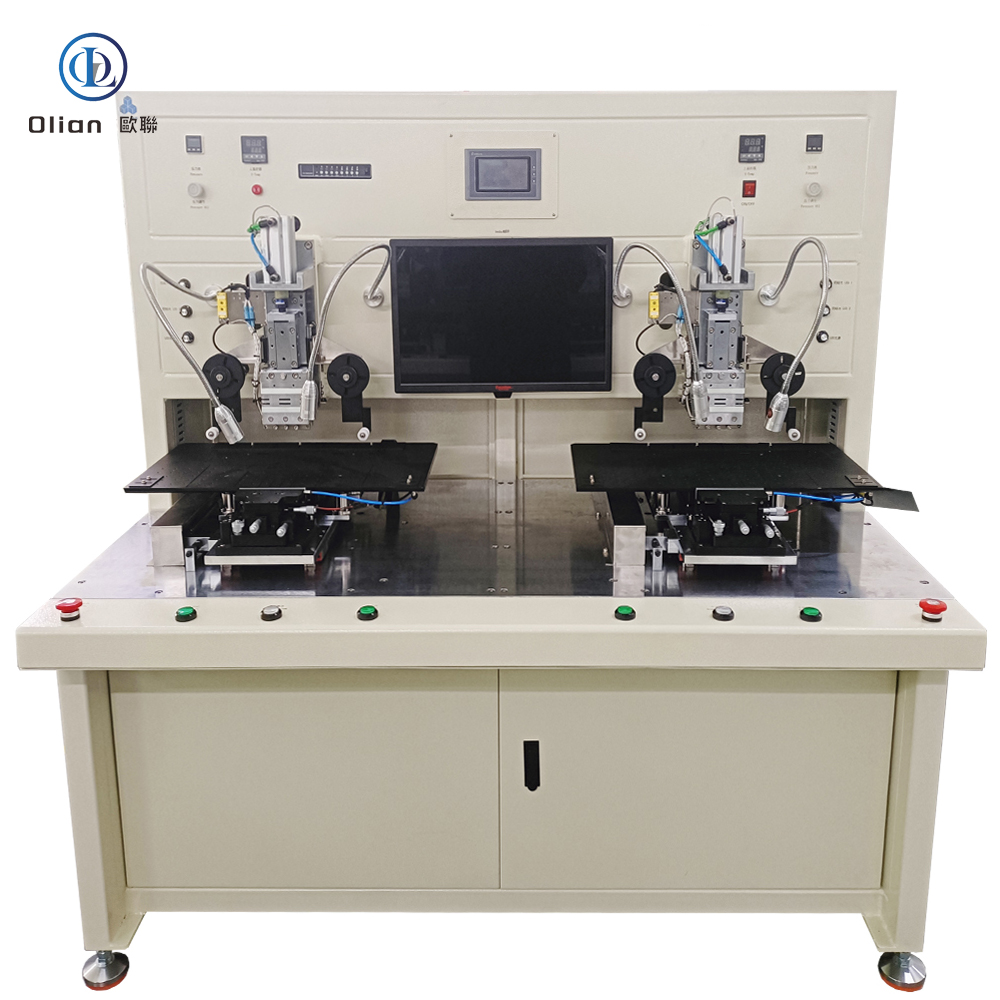
OL-FP156 – 15.6-Inch Dual-Station FOG Bonding Machine with Bottom Vision Alignment
OL-FP156 – 15.6-Inch Dual-Station FOG Bonding Machine
High-Precision Thermal Compression System for Front & Rear COF/FOG Bonding on LCD Panels
The OL-FP156 by Olian Automatic Equipment Co., Ltd. is a semi-automatic dual-station FOG (Film-on-Glass) bonding machine engineered for the final thermal compression of COF (Chip-on-Film) flex circuits onto both front and rear edges of large-format rigid LCD panels up to 15.6 inches. Featuring bottom-side vision alignment and dual independent workstations, this system delivers exceptional positional accuracy while enabling continuous production—ideal for high-mix, medium-volume manufacturing of automotive displays, industrial HMIs, and premium consumer electronics.
Unlike top-alignment systems, the bottom-view camera design ensures direct imaging of panel bonding pads through the glass substrate, eliminating parallax errors and enabling sub-micron-level registration between COF terminals and ITO traces—even on dark or reflective panels.
⚠️ Note: This machine assumes that ACF has already been applied to the panel. It performs final main bonding only, not ACF lamination or pre-bonding.
🔍 Key Technical Features
✅ Dual-Station Continuous Workflow
Two independent vacuum platforms allow simultaneous loading/unloading and bonding
While Station 1 bonds, the operator prepares Station 2—maximizing uptime and throughput
Ideal for lean production cells requiring minimal operator idle time
✅ Bottom Vision Alignment System
Camera Type: High-resolution industrial CMOS
Lens Magnification: 2× optical zoom
Field of View (FOV): 1.9 mm × 1.4 mm
Lighting: Coaxial LED illumination for glare-free imaging of reflective pads
Inter-Camera Distance: Adjustable from 12 mm to 90 mm to accommodate various COF pitches
Alignment Method: Manual fine-tuning via joystick or micrometer knobs under live camera view
✅ Bonding Performance
Panel Compatibility:
Max Size: 350 mm × 250 mm (~15.6″ diagonal)
Thickness: 0.2 – 2.2 mm
COF Dimensions:
Width: 12 – 30 mm
Length: 12 – 60 mm
Thickness: 0.02 – 0.2 mm
Bonding Force: Servo-controlled, 20–120 N (±3 N repeatability)
Temperature Range: Up to 400°C with ±2°C uniformity
Bonding Time: 0.1 – 99.9 seconds (programmable)
✅ Buffer Tape Handling (for COF Carrier)
Buffer Tape Inner Diameter: ≥33 mm
Outer Diameter: ≤80 mm
Feed Pitch: Adjustable from 1 mm to 20 mm
Safety Feature: Machine triggers alarm if tape fails to advance, preventing missed bonds
🖥️ Control & Operation
Control Unit:
PLC-based logic controller
Color touchscreen HMI (Chinese interface)
Manual control buttons for emergency override
Operating Modes:
Manual Mode: Full operator control over alignment and bonding
Auto Mode: One-button cycle after visual alignment confirmation
Ergonomics:
Work height: 890 ± 30 mm
Clean, uncluttered layout for easy access and maintenance
📏 Machine Physical Data
Dimensions: Approx. 1420 mm (W) × 1210 mm (D) × 1912 mm (H)
Weight: ~780 kg
Power Supply: AC 220V, 50/60 Hz, single-phase
Compressed Air: 0.4–0.7 MPa
Operating Environment:
Cleanroom required (ISO Class 8 or better)
Temperature: 22–27°C | Humidity: 40–70% RH
🛡️ Quality Assurance & Support
Documentation: Includes 1 Chinese-language operation manual
Target Applications: Automotive center displays, dual-driver industrial panels, medical monitors, gaming laptops
🔎 SEO Keywords (for Global Visibility)
FOG bonding machine, FOG bonder, FOG Binding machine, FOG equipment,15.6 inch dual-station FOG bonding machine, OL-FP156 Olian, bottom alignment COF bonding machine, front and rear FOG bonder for LCD, dual-platform Film-on-Glass machine with vision system, 2x magnification bottom camera COF aligner, coaxial LED FOG bonding equipment, high-precision COF main bonder for automotive displays, OL-FP156 technical specifications, servo FOG bonder with buffer tape alarm.