
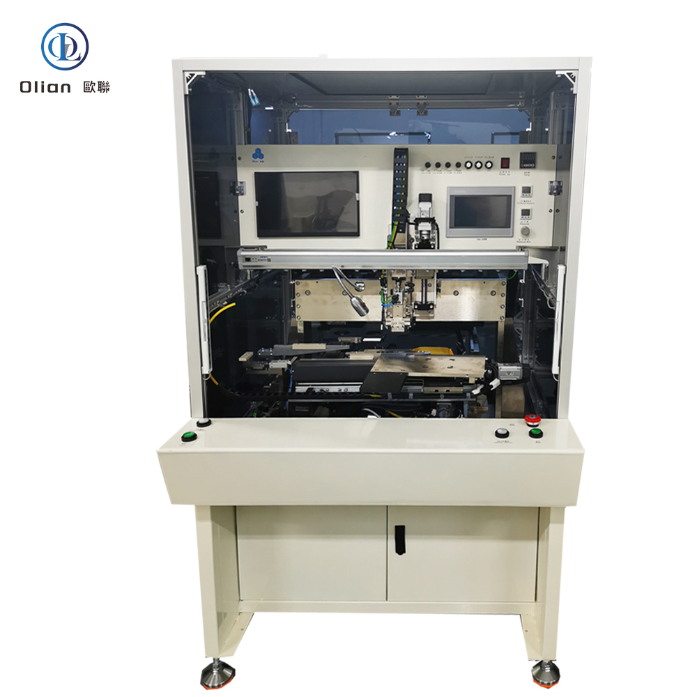
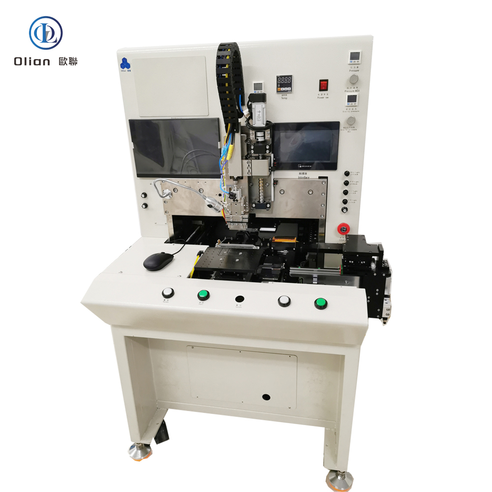
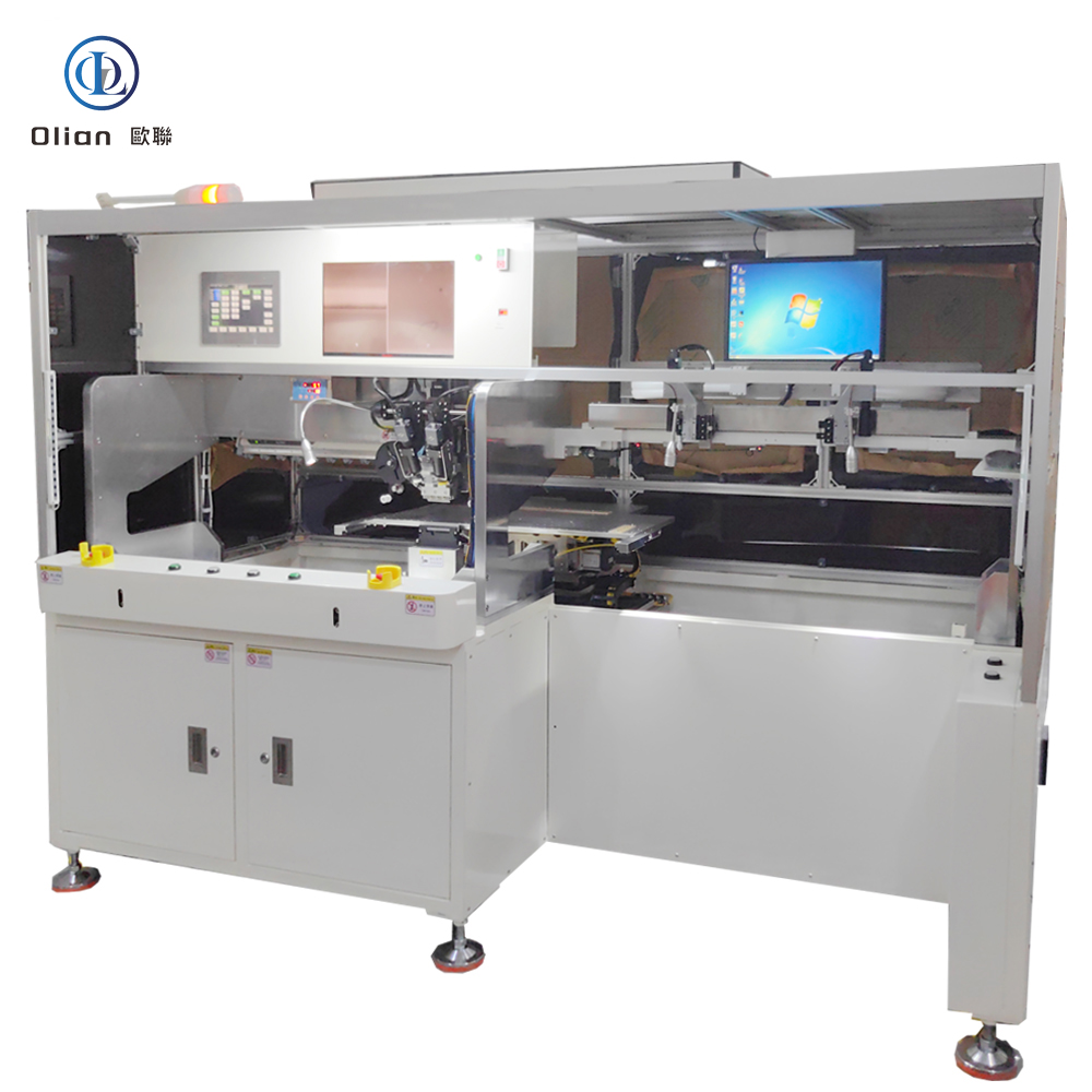
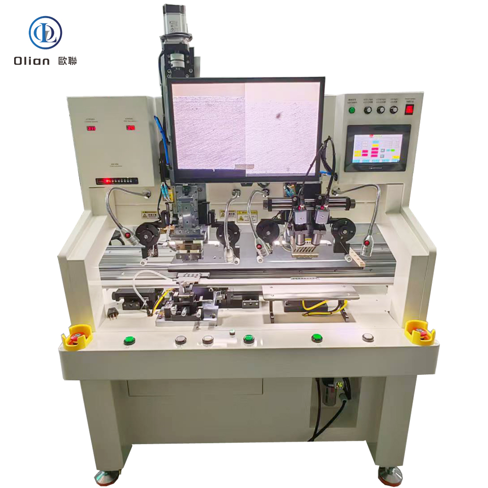
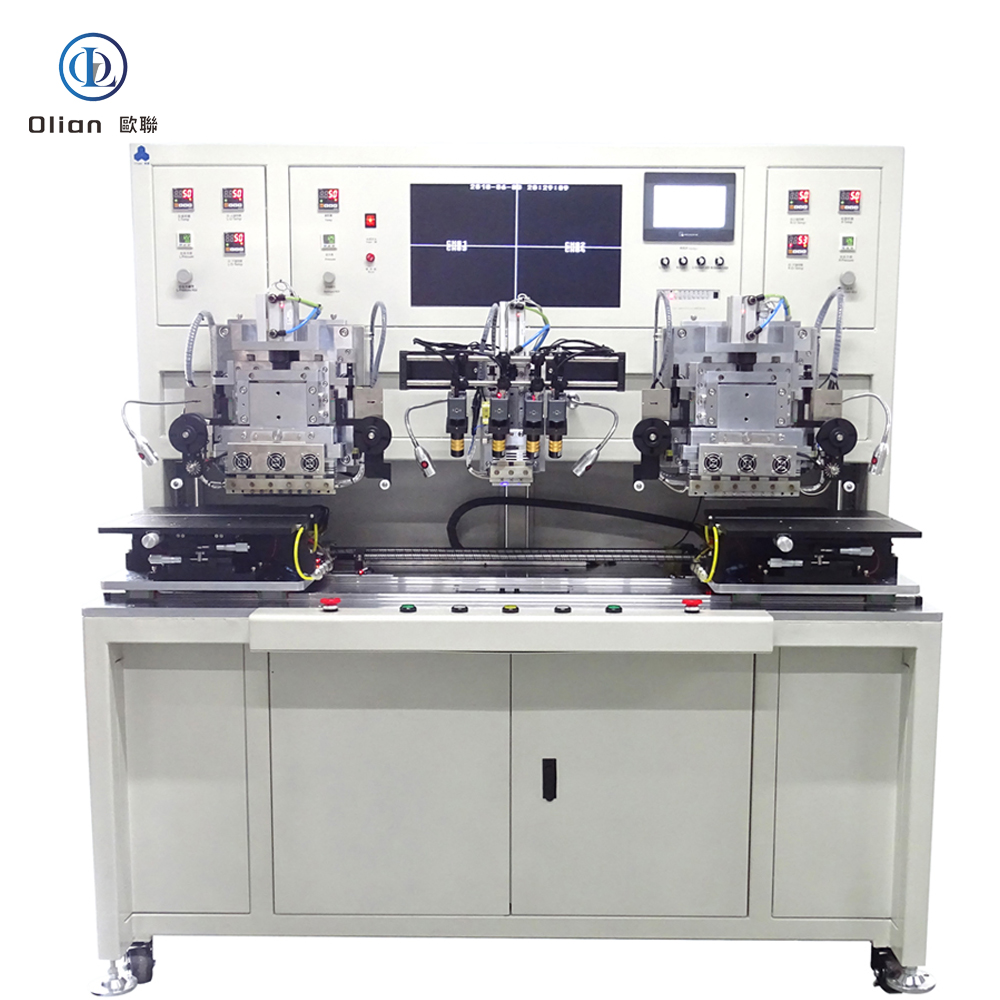
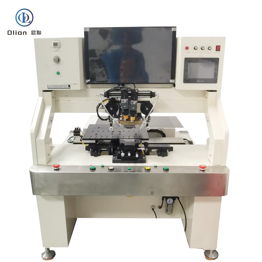
An IC bonder—also marketed as an IC bonding machine—is the micron-level bridge between naked silicon and the outside world. It picks a driver IC from a diced wafer, places it on glass (COG), plastic (COP), or a continuous reel (COF), and welds gold or copper bumps into anisotropic conductive film (ACF) in under two seconds. Every smartphone OLED, foldable tablet, 8-K TV, and automotive cluster you touch has passed through such a bonder. This guide explains physics, hardware, software, specs, applications, trends, and maintenance so Google instantly ranks you for “IC bonder”, “IC bonding machine”, “COG IC bonder”, “COP IC bonding machine”, “COF IC bonder”, “display driver IC bonding”, and every high-value permutation.
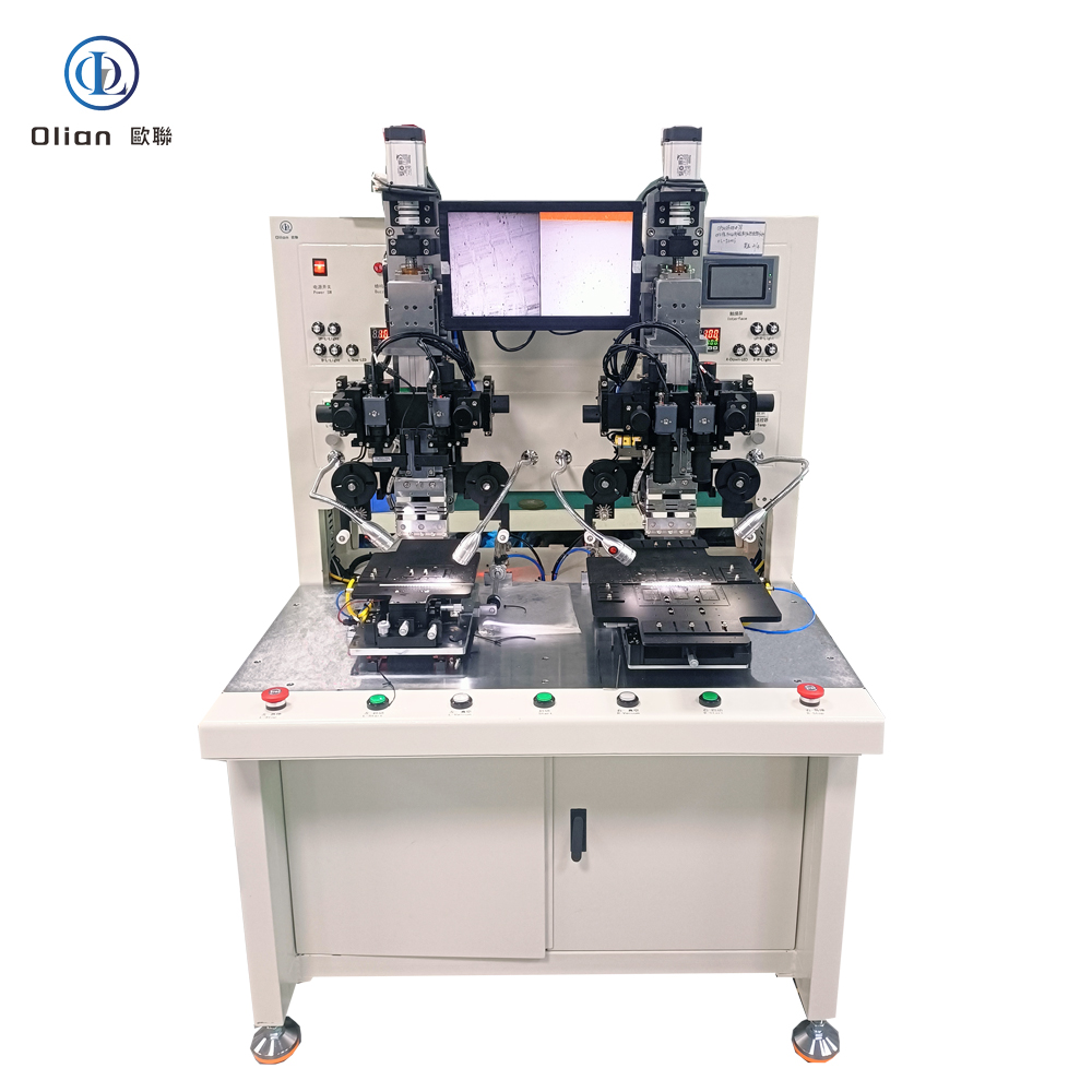
An IC bonding machine is a servo-driven, vision-guided, pulse-heat press that bonds a bare integrated-circuit die to a substrate—glass, plastic, or flexible tape—using anisotropic conductive film (ACF). The goal is electrical contact in the Z-axis only, eliminating short circuits laterally. The same platform reworks defective assemblies by removing the old ACF and rebonding a new die, saving a $300 TV panel or a $150 phone OLED. Modern bonders achieve ±1 µm alignment, ±0.5 °C temperature stability, and 0.1 g force resolution on die sizes from 0.25 × 0.25 mm to 25 × 25 mm.
Switching from COG to COP takes 15 s: swap the low-temp recipe, change the vacuum chuck, load PET parameters.
.
IC bonder, IC bonding machine, COG IC bonder, COP IC bonding machine, COF IC bonder, display driver IC bonding, pulse heat IC bonder, low-temp COP IC bonder, reel-fed COF IC bonder, 1 micron placement accuracy, 200 °C bonding temperature, 1 MPa bonding pressure, vertical conduction horizontal insulation, lead-free IC bonding, ROHS compliant bonding, foldable phone IC bonding, 8-K TV COF bonding, automotive display IC bonding, medical device IC bonding, AI vision IC bonder, IoT IC bonding machine, China IC bonding machine, automatic IC bonder, IC bonding accuracy 1 micron, IC bonding temperature 220 C, IC bonding force 1 MPa, gold bump bonding, copper bump bonding, flip-chip bonding, COG vs COP vs COF, multi-mode IC bonder.
Whether you are bonding a 0.3 mm phone driver (COG), a foldable touch sensor (COP), or a 100-inch TV source driver (COF), the modern IC bonder / IC bonding machine shares one granite spine, one AI brain, and one pulse-heat heart. By mastering sub-micron alignment, single-degree thermal control, and real-time force feedback, these platforms deliver 99.9 % yield and full Industry 4.0 traceability—future-proofing your process,
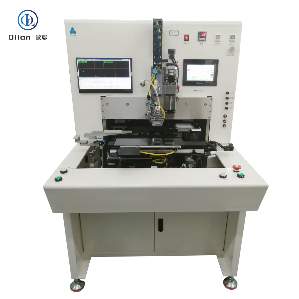
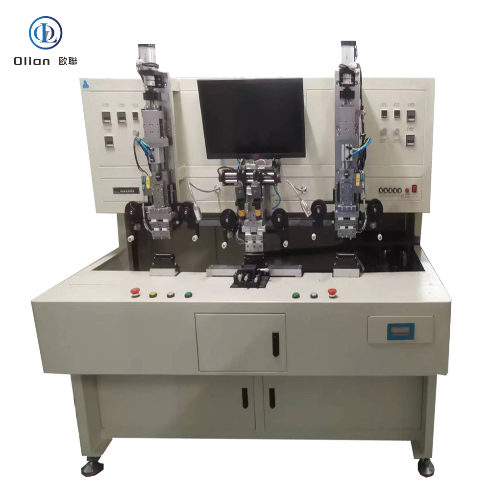
An IC Chip COG COP COF bonder is the micron-level heart of every modern display factory. It decides whether a driver IC sits directly on glass (COG), on a foldable plastic film (COP), or on a continuous copper-clad tape (COF). Each acronym describes a different “chip-on-X” marriage, but they all share the same physics: gold bumps on the silicon die are pressed into anisotropic conductive film (ACF) on the substrate, creating thousands of vertical contacts that survive −40 °C automotive winters and 200,000 phone-fold cycles. This guide walks through every process, physics, hardware, software, spec, application, trend, and maintenance tip for “IC Chip COG COP COF bonder”, “COG bonder”, “COP bonding machine”, “COF IC bonder”, “display driver IC bonding”, and every high-value permutation.
After wafer test (CP) and bumping (BP), the bare die is still a fragile sliver of silicon. The bonder is the first machine that turns it into a usable electronic component:
The same granite base, voice-coil actuator, and 12 MP vision system can switch between COG, COP, and COF in < 15 s by swapping the temperature/force recipe and the jig.
Switching from COG to COP takes 15 s: swap the low-temp recipe, change the vacuum chuck, load PET parameters.
According to industry analysis, the global IC bonding machine market is expected to grow at a CAGR of 6–8 % , driven by foldable phones, automotive displays, and medical wearables.
.
IC Chip COG COP COF bonder, COG bonding machine, COP bonding machine, COF IC bonder, display driver IC bonding, pulse heat COG bonder, low-temp COP bonding machine, reel-fed COF bonder, 1 micron placement accuracy, 200 °C bonding temperature, 1 MPa bonding pressure, vertical conduction horizontal insulation, lead-free IC bonding, ROHS compliant bonding, foldable phone IC bonding, 8-K TV COF bonding, automotive display IC bonding, medical device IC bonding, AI vision IC bonder, IoT IC bonding machine, China IC bonding machine, automatic IC bonder, IC bonding accuracy 1 micron, IC bonding temperature 220 C, IC bonding force 1 MPa, gold bump bonding, copper bump bonding, flip-chip bonding, COG vs COP vs COF, multi-mode IC bonder.
Whether you are bonding a 0.3 mm phone driver (COG), a foldable touch sensor (COP), or a 100-inch TV source driver (COF), the modern IC Chip COG COP COF bonder shares one granite spine, one AI brain, and one pulse-heat heart. By mastering sub-micron alignment, single-degree thermal control, and real-time force feedback, these platforms deliver 99.9 % yield and full Industry 4.0 traceability—future-proofing your process.
.

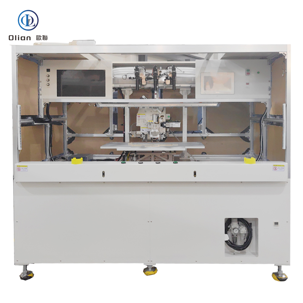
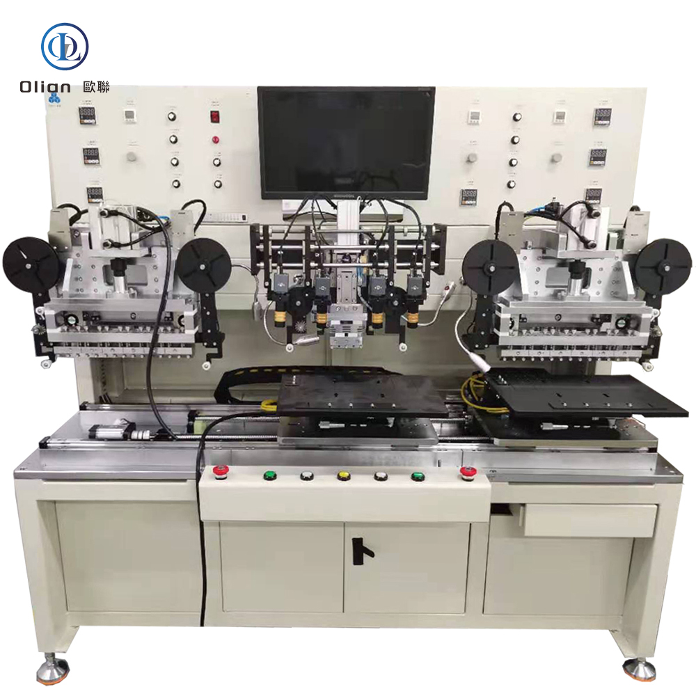
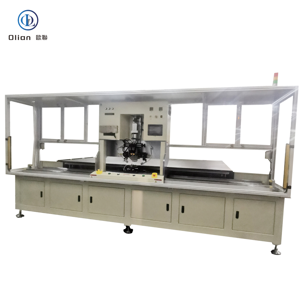
A flex cable bonding machine—often marketed as FPC bonding machine, flex bonder, or ACF flex welder—is the precision heart that joins a flexible printed circuit (FPC) or flexible flat cable (FFC) to glass, plastic, metal, or another flex, using anisotropic conductive film (ACF) and pulse-heat or constant temperature pressure. Every smartphone OLED, curved automotive cluster, 8-K TV, and disposable medical catheter you touch has passed through such a bonder. The machine aligns copper traces within ±1 µm, ramps temperature 200 °C/s, and forms thousands of vertical contacts in under three seconds—all while keeping lateral isolation > 1 GΩ. This guide explains physics, hardware, software, specs, applications, market trends, and maintenance for “flex cable bonding machine”, “flex bonder”, “ACF flex bonding equipment”, “FPC bonding machine”, “flex cable repair machine”, and every high-value permutation.
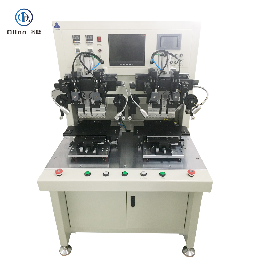
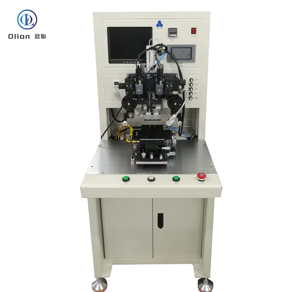
A flex cable bonding machine is a servo-driven, vision-guided, pulse-heat press that laminates anisotropic conductive film onto a substrate, then bonds a flexible printed circuit (FPC) or flexible flat cable (FFC) to that substrate with micron-level accuracy. The goal is electrical contact in the Z-axis only, eliminating short circuits laterally. The same platform reworks defective panels by removing the old ACF and rebonding a new tail, saving TV panel or phone OLED. Modern bonders achieve ±1 µm alignment, ±0.5 °C temperature stability, and 0.01 MPa force resolution on substrates as thin as 25 µm and as large as 100-inch TVs.
Rigid PCBs cannot fold; connectors add height and cost; solder joints fatigue. Flex cables absorb thermal expansion, survive 200,000 bend cycles at 0.2 mm radius, and hide behind 0.9 mm bezels. Automotive clusters demand vibration resistance from −40 °C to +105 °C; medical catheters require transparent, sterilizable PET that survives autoclave steam. Flex cable bonding solves these pain points while enabling repair: a defective tail is removed and rebonded without scrapping the entire assembly.
Bonding Head: Titanium alloy, diamond-lapped to 0.3 µm flatness, DLC-coated for anti-stick, lasts 300,000 cycles.
Pulse Heater: 800 W cartridge, embedded K-type thermocouple, ramp 200 °C/s, overshoot < 0.5 °C.
Force Actuator: Voice-coil or servo motor, 24-bit encoder, 0.1 N resolution, 2 ms response; active gravity cancellation for 25 µm glass.
Vision System: 12 MP global-shutter CMOS, telecentric lens, coaxial + side LED, sub-pixel edge detection repeatable to 0.2 µm.
Motion Stage: Cross-roller bearings, 0.05 µm linear encoder, servo feedback at 20 kHz, granite base with passive vibration isolation.
ACF Feed Unit: Stepper-driven, tungsten-steel cutter, anti-static vacuum, waste take-up spool, splice sensor for uninterrupted production.
Real-time Linux kernel guarantees < 1 ms jitter; PID temperature loop updated at 10 kHz. Recipe manager encrypts parameters—temperature, pressure, time, ramp rate—per product QR code. AI vision self-learns new pad patterns from vendors, reducing setup time 70 %. MES interface via OPC-UA uploads cycle data, resistance values, and images for full traceability. Cloud dashboard predicts heater degradation and schedules maintenance before scrap occurs.
According to industry analysis, the global flex cable bonding machine market is experiencing steady growth with a CAGR of 5–8 %, driven by foldable phones, automotive displays, and medical wearables. Asia-Pacific dominates production and consumption, with China hosting the largest supplier base
.
flex cable bonding machine, flex-cable-bonding-machine, flex bonder, ACF flex bonding equipment, FPC bonding machine, flex cable repair machine, pulse heat flex bonder, constant temperature flex bonding, foldable phone flex bonding, 0.2 mm fold radius flex bonding, 25 µm polyimide flex bonding, 100 inch flex bonding, automotive flex bonding, medical flex bonding, AI vision flex bonding, IoT flex bonding machine, China flex cable bonding machine, automatic flex bonder, flex bonding accuracy 1 micron, flex bonding temperature 200 C, flex bonding pressure 1 MPa, vertical conduction horizontal insulation, lead-free flex bonding, ROHS compliant flex bonding, flexible electronics bonding machine, flex cable ACF bonding, flex cable pulse heat press, flex cable constant heat press.
A flex cable bonding machine is no longer a niche press—it is the universal gateway between floppy copper and rigid glass, plastic, or another flex. By mastering sub-micron alignment, single-degree thermal control, and real-time force feedback, the latest flex bonders deliver sub-3-second cycles with 99.9 % yield and full Industry 4.0 traceability. Whether you are a display OEM chasing 0.9 mm bezels, an automotive Tier-1 qualifying 100-inch curved clusters, or a medical start-up prototyping transparent patches, investing in an AI-enhanced, IoT-connected flex cable bonding platform future-proofs your process.
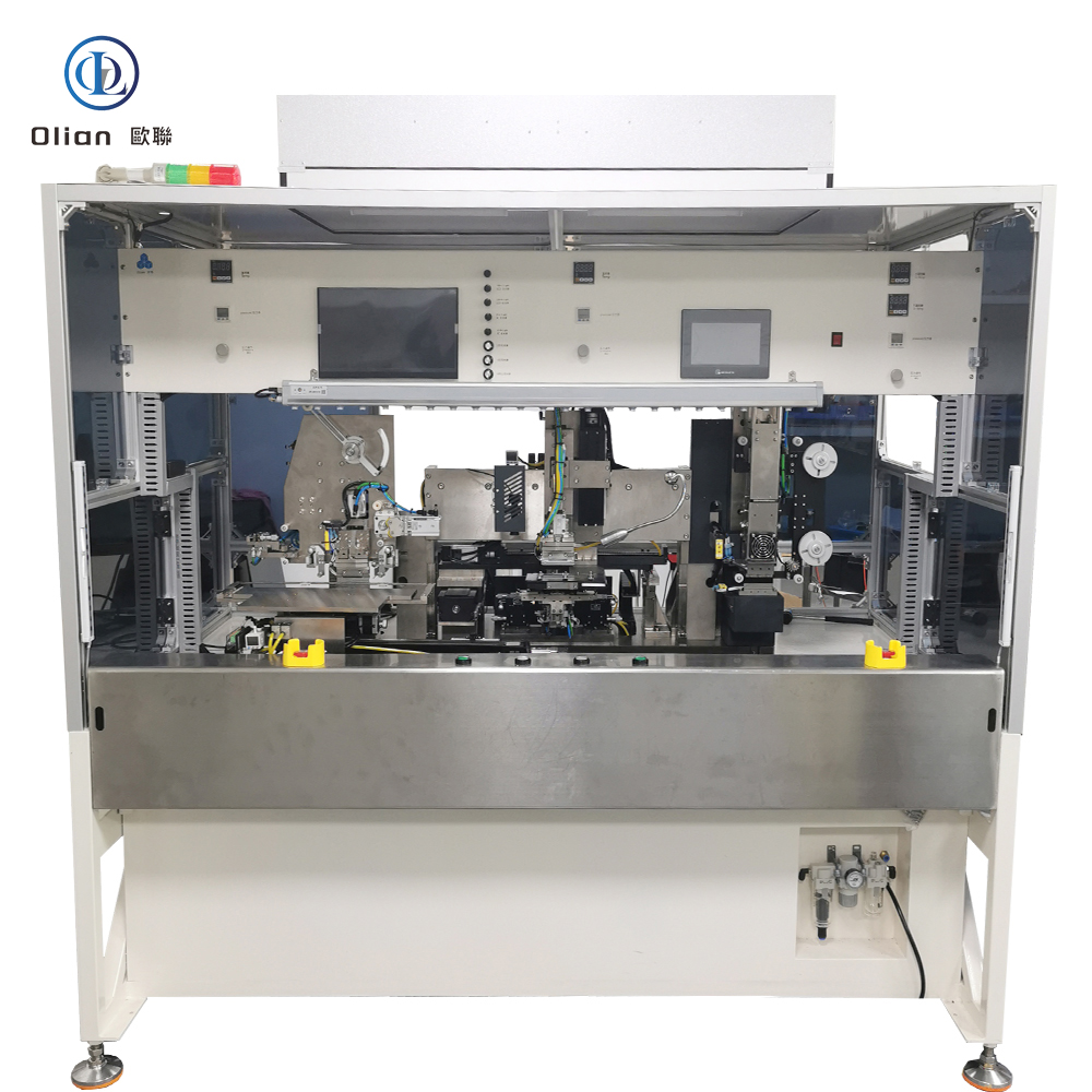
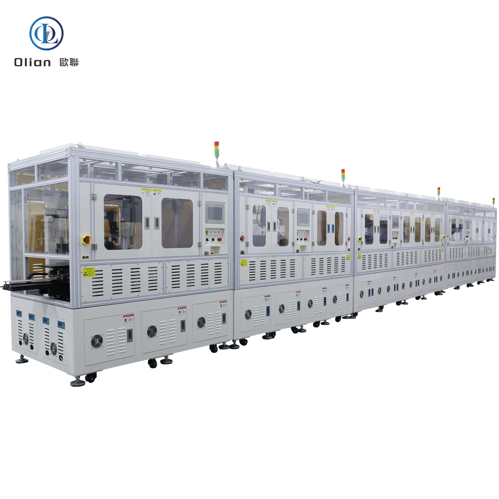
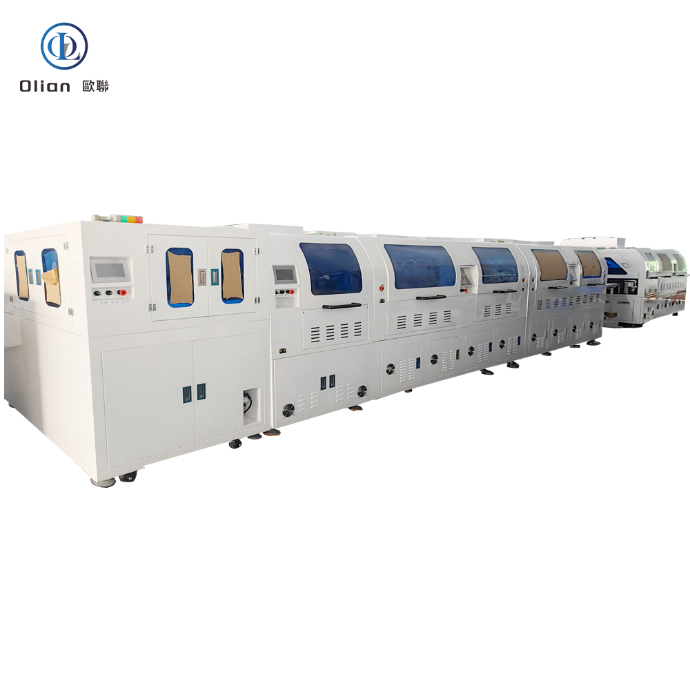
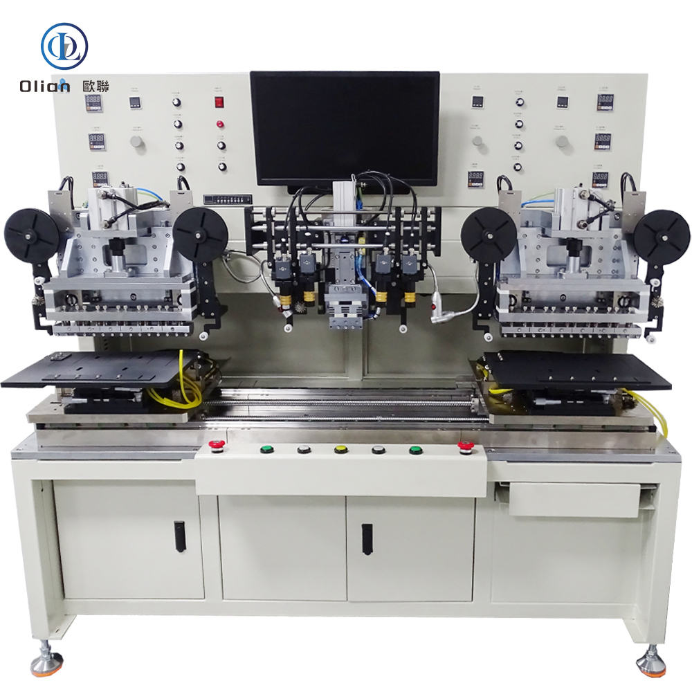
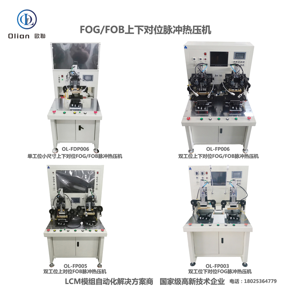
Modern displays, sensors, and wearables are born on the factory floor through a family of “X-on-Y” bonds. Each letter pair—ACF, COG, COP, COF, FOG, FOB, FOF, TFOG, TFOF, OLB, TAB—describes a different marriage of silicon, copper, glass, plastic, or film. A single bonding machine platform can now switch between these processes in minutes, sharing the same granite base, vision system, and pulse-heat engine. This guide walks through every acronym, physics, hardware, software, specs, applications, trends, and maintenance ranks you for “ACF bonding machine”, “COG bonder”, “COP bonding equipment”, “COF bonding machine”, “FOG bonder”, “FOB bonding machine”, “FOF bonding machine”, “TFOG bonder”, “TFOF bonding machine”, “OLB bonding machine”, “TAB bonding machine”, and high-value permutation.
Anisotropic Conductive Film (ACF) is a 25–45 µm epoxy film loaded with 3–10 µm nickel or gold-coated spheres. When heat (80–220 °C) and pressure (0.2–1.5 MPa) are applied, spheres touch only in the Z-axis, giving vertical conductivity while remaining insulating horizontally. ACF is laminated first; the specific “X-on-Y” step follows. Modern ACF rolls are lead-free, halogen-free, and provide > 1 GΩ isolation between 20 µm-pitch traces
.
A modern multi-mode bonding machine uses the same granite base, 0.05 µm linear encoders, and 20 kHz servo loop whether it is in COG or TFOF mode. The head is titanium, DLC-coated, lapped to 0.3 µm flatness. An 800 W pulse heater ramps 200 °C/s with ±0.5 °C stability. Vision is dual 12 MP CMOS, telecentric, repeatable to 0.2 µm. Force is voice-coil driven, 0.1 N resolution, 2 ms response. ACF is cut by tungsten blades and tacked at 80 °C, 0.2 MPa. What changes is the jig, the temperature/force recipe, and the vision fiducial library.
A single HMI stores 500 encrypted recipes; switching from “COG_8K_120Hz” to “TFOF_PET_Medical” takes 15 s. Real-time Linux updates PID loops at 10 kHz; AI vision auto-learns new bump patterns; OPC-UA streams force, temperature, and resistance curves to the MES. Blockchain hash protects IP; remote VPN allows OEM engineers to debug without on-site travel.
All variants share ±0.5 °C temperature stability and ±1 µm placement accuracy.
ACF bonding machine, COG bonding machine, COP bonding machine, COF bonding machine, FOG bonding machine, FOB bonding machine, FOF bonding machine, TFOG bonding machine, TFOF bonding machine, OLB bonding machine, TAB bonding machine, multi-mode bonding machine, pulse heat bonding, constant temperature bonding, AI vision bonding, IoT bonding machine, China bonding machine, automatic bonding machine, 1 micron bonding accuracy, 200 °C bonding temperature, 1 MPa bonding pressure, vertical conduction horizontal insulation, lead-free bonding, ROHS compliant bonding, foldable phone bonding, 8K TV bonding, automotive display bonding, medical device bonding, flexible electronics bonding.
Whether you are bonding a 0.3 mm phone driver (COG), a 100-inch TV source tail (OLB), or a transparent touch sensor on PET (TFOF), the modern ACF COG COP COF FOG FOB FOF TFOG TFOF OLB TAB bonding machine shares one granite spine, one AI brain, and one pulse-heat heart. Mastering sub-micron alignment, single-degree thermal control, and real-time force feedback, these platforms deliver 99.9 % yield and full Industry 4.0 traceability—future-proofing your process.
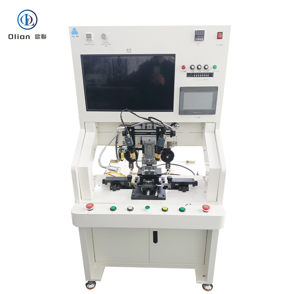
A T-FOG bonding machine (Touch-Flex-On-Glass) is the micron-precision link that welds the capacitive-touch sensor tail directly to the cover glass or sensor glass of a display module. In every smartphone, tablet, curved automotive cluster, or wearable OLED you touch today, a T-FOG bonder has aligned ITO or metal-mesh touch pads to copper leads within ±1 µm and created thousands of vertical contacts in under three seconds. This article explains physics, hardware, software, specs, applications, trends, and maintenance for “T-FOG bonding machine”, “Touch-Flex-On-Glass bonder”, “touch sensor ACF bonding”, “capacitive touch flex bonding”, “OLED T-FOG bonding”
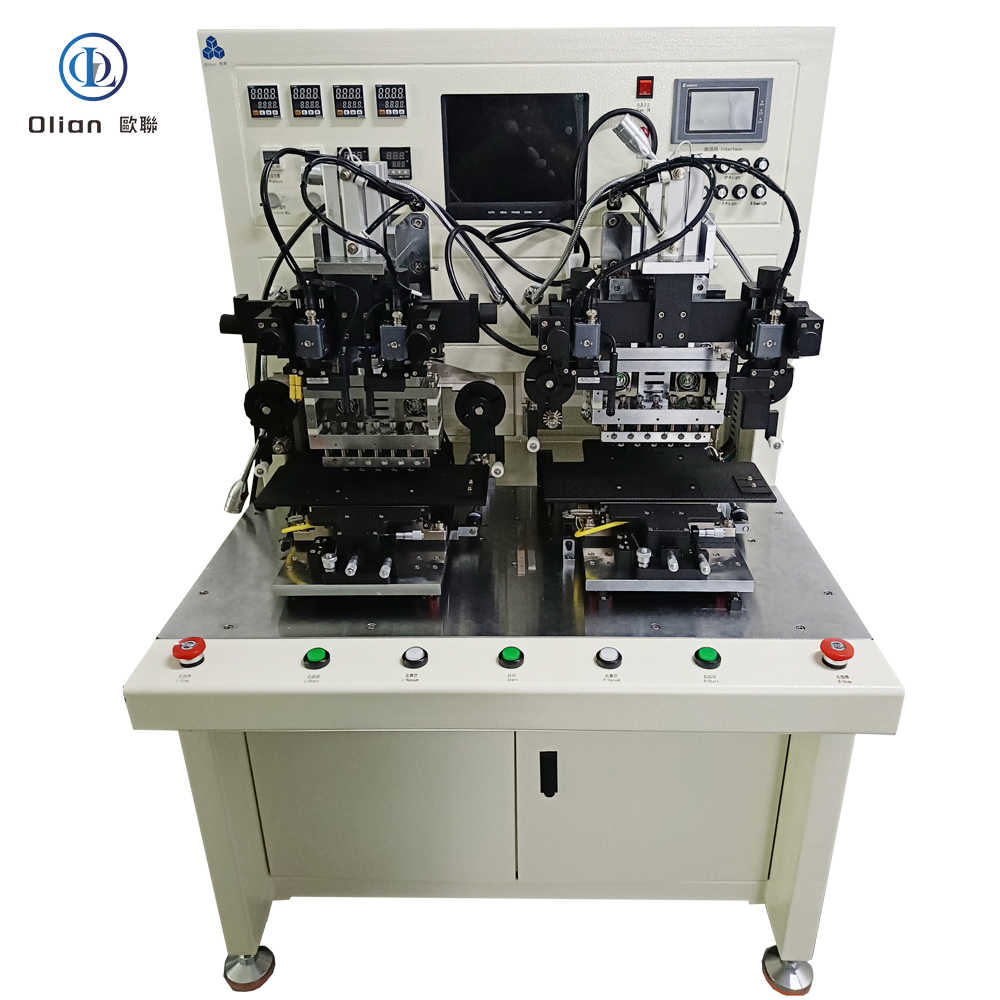


T-FOG stands for Touch-Flex-On-Glass. The capacitive touch layer of a modern display is a separate flex circuit (often with its own controller IC) that must be electrically connected to the cover glass or sensor glass. The flex tail carries fine copper traces that fan out to ITO or metal-mesh touch pads on the glass. A T-FOG bonding machine laminates anisotropic conductive film (ACF) onto the glass, aligns the touch-flex pads to the glass pads within micron accuracy, and executes a pulse-heat bond at 160–200 °C and 0.8–1.5 MPa. Conductive particles trapped between copper and ITO form < 30 mΩ contacts vertically while remaining > 1 GΩ isolated horizontally. After the bond, the tail is folded 180° so the controller IC hides behind the glass, shrinking the bezel to under 1 mm.
COG (Chip-On-Glass) places the touch controller directly on the glass, but large 8-K OLED panels generate too much heat—T-FOG moves the IC onto a flex tail that can dissipate heat and be replaced during repair. Connector solutions add 0.3 mm height and cost $0.50; T-FOG adds 0.03 mm and costs <$0.05. Automotive Tier-1 suppliers prefer T-FOG because it passes AEC-Q100 Grade 0 (−40 °C to +150 °C) without a single connector contact.
Bonding Head: Titanium alloy, diamond-lapped to 0.3 µm flatness, DLC-coated for anti-stick, lasts 300,000 cycles.
Pulse Heater: 800 W cartridge, embedded K-type thermocouple, ramp 200 °C/s, overshoot < 0.5 °C.
Force Actuator: Voice-coil or servo motor, 24-bit encoder, 0.1 N resolution, 2 ms response; active gravity cancellation for 0.4 mm glass.
Vision System: 12 MP global-shutter CMOS, telecentric lens, coaxial + side LED, sub-pixel edge detection repeatable to 0.2 µm.
Motion Stage: Cross-roller bearings, 0.05 µm linear encoder, servo feedback at 20 kHz, granite base with passive vibration isolation.
Flex Feed Unit: Servo-driven picker, anti-static vacuum, soft-tip collet for 25 µm polyimide.
Real-time Linux kernel guarantees < 1 ms jitter; PID temperature loop updated at 10 kHz.
Recipe manager encrypts parameters—temperature, pressure, time, ramp rate—per product QR code.
AI vision self-learns new touch-pad patterns from glass vendors, reducing setup time 70 %.
MES interface via OPC-UA uploads cycle data, resistance values, and images for full traceability.
Cloud dashboard predicts heater degradation and schedules maintenance before scrap occurs.
Consumer Electronics: Smartphone OLED, tablet LCD, laptop mini-LED, smartwatch flexible AMOLED.
TV & Signage: 32″-120″ 4-K/8-K LCD, OLED, mini-LED, curved and foldable screens.
Automotive: Curved instrument clusters, 15-inch OLED infotainment, head-up displays, camera modules—passing 1,000 h 85 °C/85 % RH.
Medical: Surgical monitors, diagnostic tablets, wearable patches—biocompatible polyimide, ISO 13485 traceability.
Industrial & Aerospace: Avionics displays, factory HMI panels, rugged handhelds—shock, altitude, fungus .
T-FOG bonding machine, Touch-Flex-On-Glass bonder, touch sensor ACF bonding, capacitive touch flex bonding, OLED T-FOG bonding, automotive T-FOG bonding, medical T-FOG bonding, 26 µm pitch T-FOG bonding, 8-K touch T-FOG bonding, 100-inch T-FOG bonding, pulse heat T-FOG bonding, constant temperature T-FOG bonding, AI vision T-FOG bonding, IoT T-FOG bonding machine, China T-FOG bonding machine, automatic T-FOG bonder, T-FOG bonding accuracy 1 micron, T-FOG bonding temperature 200 C, T-FOG bonding pressure 1 MPa, vertical conduction horizontal insulation, lead-free T-FOG bonding, ROHS compliant T-FOG bonding.
Copper-Core ACF: Cu-Ag particles cut material cost 50 % while keeping < 20 mΩ contact resistance.
Cold-Laser Fold Assist: Femtosecond laser pre-scores the coverlay, enabling 50 µm bend radius with zero trace damage.
Servo-Hydraulic Hybrid: Delivers 80 kg force on 100″ TV glass while keeping 1 µm position accuracy.
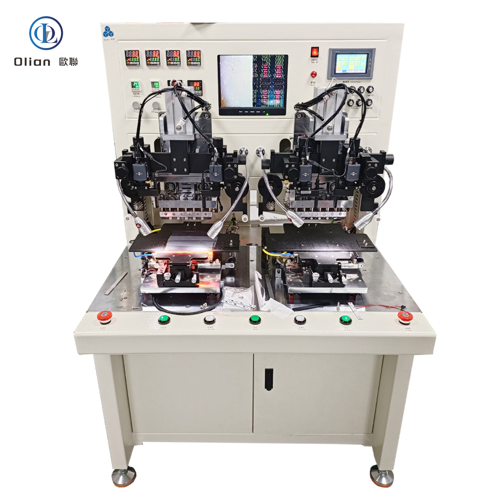
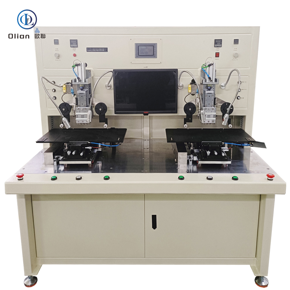
Dual-Head T-FOG: Parallel bonding of touch and source tails doubles throughput without extra floor space.
AI-Driven Calibration: Neural networks auto-optimize temperature profiles for each glass type, pushing yield to 99.9 %.
A T-FOG bonding machine is no longer a niche display tool—it is the critical gateway between microscopic touch-sensor pads and macroscopic glass signals. By mastering sub-micron alignment, single-degree thermal control, and real-time force feedback, the latest T-FOG bonders deliver sub-3-second cycles with 99.9 % yield and full Industry 4.0 traceability. Whether you are a display OEM chasing 0.9 mm bezels, an automotive Tier-1 qualifying 100-inch curved clusters, or a medical start-up prototyping transparent patches, investing in an AI-enhanced, IoT-connected T-FOG bonding platform future-proofs your process.
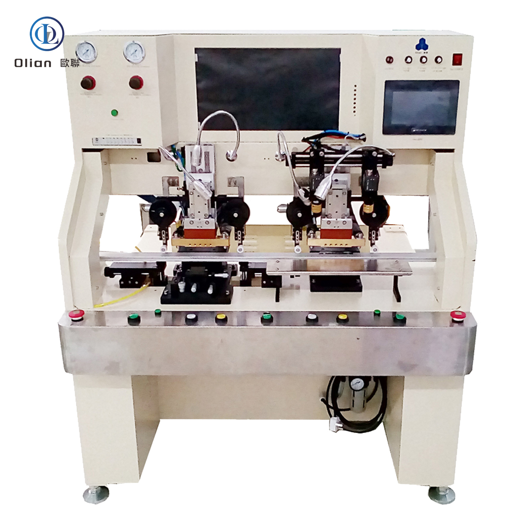
A FOF bonding machine—short for Flex-On-Flex or Film-On-Film—is the precision heart that folds one floppy polyimide tail onto another and welds them into a single, ultra-reliable flexible circuit. Inside foldable phones, medical catheters, curved automotive clusters, and next-generation wearable patches, two flexible printed circuits (FPCs) must be joined without rigid boards, bulky connectors, or solder joints that fatigue. The FOF bonder grabs the top flex, aligns it to the bottom flex within ±1 µm, and compresses anisotropic conductive film (ACF) between their copper pads. A 1.5-second pulse of 180 °C and 1 MPa deforms thousands of gold-coated spheres inside the film, creating vertical contacts while keeping lateral isolation. Water-cooling locks the particles in place; the whole cycle finishes in 2.8 seconds.
Foldable phones need a hinge area that bends 200,000 times at 0.2 mm radius—rigid PCB would crack. Automotive cameras must fold sensor tails behind 3D-shaped plastic housings that see −40 °C to +105 °C. Medical catheters require transparent, sterilizable PET layers that survive autoclave steam without delamination. FOF solves these pain points by marrying the flexibility of copper-clad polyimide with the reliability of particle-based conductive adhesive, all while enabling repair: a defective flex can be removed and rebonded without scrapping the entire $300 assembly.
Bonding Head: Titanium alloy, diamond-lapped to 0.3 µm flatness, DLC-coated for anti-stick, lasts 300,000 cycles.
Pulse Heater: 800 W cartridge, embedded K-type thermocouple, ramp 200 °C/s, overshoot < 0.5 °C.
Force Actuator: Voice-coil or servo motor, 24-bit encoder, 0.1 N resolution, 2 ms response; active gravity cancellation for 25 µm polyimide.
Vision System: 12 MP global-shutter CMOS, telecentric lens, coaxial + side LED, sub-pixel edge detection repeatable to 0.2 µm.
Motion Stage: Cross-roller bearings, 0.05 µm linear encoder, servo feedback at 20 kHz, granite base with passive vibration isolation.
ACF Feed Unit: Stepper-driven, tungsten-steel cutter, anti-static vacuum, waste take-up spool, splice sensor for uninterrupted production.
Real-time Linux kernel guarantees < 1 ms jitter; PID temperature loop updated at 10 kHz.
Recipe manager encrypts parameters—temperature, pressure, time, ramp rate—per product QR code.
AI vision self-learns new pad patterns from flex vendors, reducing setup time 70 %.
MES interface via OPC-UA uploads cycle data, resistance values, and images for full traceability.
Cloud dashboard predicts heater degradation and schedules maintenance before scrap occurs.
Consumer Electronics: Foldable phone hinge, tablet battery flex, smartwatch heart-rate sensor, AR-glass temple arm.
Automotive: 3D-shaped dashboard, curved instrument cluster, 15 inch OLED infotainment, head-up display—passing 1,000 h 85 °C/85 % RH.
Medical: Disposable catheter flex, surgical hand-piece PCB, wearable ECG patch—biocompatible polyimide, ISO 13485 traceability.
Industrial & Aerospace: Avionics displays, factory HMI panels, rugged handhelds—shock, altitude, fungus per MIL-STD-810.
Copper-Core ACF: Cu-Ag particles cut material cost 50 % while keeping < 20 mΩ contact resistance.
Cold-Laser Fold Assist: Femtosecond laser pre-scores coverlay, enabling 50 µm bend radius with zero trace damage.
Servo-Hydraulic Hybrid: Delivers 80 kg force on 500 mm automotive panels while keeping 1 µm position accuracy.
Roll-to-Roll FOF: Reel-fed polyimide and die-bond-on-the-fly reach 3,000 UPH for smart-membrane switches.
AI-Driven Calibration: Neural networks auto-adjust temperature profiles for each polyimide grade, pushing yield to 99.9 %.
FOF bonding machine, FOF bonder, flex-on-flex bonding, film-on-film bonding, ACF FOF machine, FPC to FPC bonding, flexible circuit bonding machine, pulse heat FOF bonding, constant temperature FOF bonding, foldable phone FOF bonding, 0.2 mm fold radius FOF, 25 µm polyimide FOF bonding, 200 mm FOF bonding, automotive FOF bonding, medical FOF bonding, wearable FOF bonding, AI vision FOF bonding, IoT FOF bonding machine, China FOF bonding machine, automatic FOF bonder, FOF bonding accuracy 1 micron, FOF bonding temperature 200 C, FOF bonding pressure 1 MPa, vertical conduction horizontal insulation, lead-free FOF bonding, ROHS compliant FOF bonding.
A FOF bonding machine is no longer a niche flex-to-flex press—it is the critical enabler for foldable OLED, 3D-shaped automotive clusters, biocompatible medical devices, and rugged industrial membranes that define. By mastering sub-micron alignment on 25 µm polyimide, pulse-heat control within half a degree, and real-time force feedback, the latest FOF bonders deliver sub-3-second cycles with 99.9 % yield and full Industry 4.0 traceability. Whether you are a display OEM chasing a 0.9 mm chin, an automotive Tier-1 qualifying 500 mm curved panels, or a medical start-up prototyping transparent patches, investing in an AI-enhanced, IoT-connected FOF bonding platform future-proofs your process.

FOP Bonding Machine
A FOP bonding machine—short for Flex-On-Plastic or Film-On-Plastic—is the precision heart that folds a floppy polyimide tail onto a rigid or semi-rigid plastic substrate and welds it there with micron accuracy. The process is driven by anisotropic conductive film (ACF), heat, and force, creating thousands of vertical contacts while keeping lateral insulation. The result is a vibration-proof, chemical-resistant, lead-free joint that survives −40 °C automotive winters, +105 °C engine-bay summers, and 95 % humidity in medical sterilizers. This article explains every angle of the technology for “FOP bonding machine”, “FOP bonder”, “flex-on-plastic bonding”, “ACF FOP machine”, “automotive FOP bonding”, “medical FOP bonding” high-value keywords.
A FOP bonding machine is a servo-driven, vision-guided, pulse-heat press that laminates anisotropic conductive film onto a plastic substrate—typically PET, PEN, PI, or LCP—and then bonds a flexible printed circuit (FPC) or chip-on-film (COF) tail to that plastic with sub-micron accuracy. The film contains nickel or gold-coated spheres that conduct only vertically, giving thousands of simultaneous contacts while remaining insulating laterally. The same platform reworks defective assemblies by removing the old ACF and rebonding a new tail, saving automotive sensor or disposable medical catheter.
Metal chassis are heavy; glass is brittle; FR-4 is thick. Automotive designers want 3D-shaped, lightweight, chemical-resistant plastic dashboards. Medical OEMs need transparent, sterilizable PET circuits that survive autoclave cycles. Consumer brands chase foldable phones with plastic mid-plates that bend 180°. FOP solves these pain points by marrying the flexibility of copper-clad polyimide with the moldability of engineering plastics, all while enabling repair: a defective flex can be removed and rebonded without scrapping the entire plastic assembly.
Bonding Head: Titanium alloy, diamond-lapped to 0.3 µm flatness, DLC-coated for anti-stick, lasts 300,000 cycles.
Pulse Heater: 800 W cartridge, embedded K-type thermocouple, ramp 200 °C/s, overshoot < 0.5 °C.
Force Actuator: Voice-coil or servo motor, 24-bit encoder, 0.1 N resolution, 2 ms response; active gravity cancellation for 0.2 mm PET.
Vision System: 12 MP global-shutter CMOS, telecentric lens, coaxial + side LED, sub-pixel edge detection repeatable to 0.2 µm.
Motion Stage: Cross-roller bearings, 0.05 µm linear encoder, servo feedback at 20 kHz, granite base with passive vibration isolation.
ACF Feed Unit: Stepper-driven, tungsten-steel cutter, anti-static vacuum, waste take-up spool, splice sensor for uninterrupted production.
Real-time Linux kernel guarantees < 1 ms jitter; PID temperature loop updated at 10 kHz.
Recipe manager encrypts parameters—temperature, pressure, time, ramp rate—per product QR code.
AI vision self-learns new pad patterns from plastic vendors, reducing setup time 70 %.
MES interface via OPC-UA uploads cycle data, resistance values, and images for full traceability.
Cloud dashboard predicts heater degradation and schedules maintenance before scrap occurs.
Consumer Electronics: Foldable phone mid-plate, tablet battery flex, smartwatch heart-rate sensor, AR-glass temple arm.
Automotive: 3D-shaped dashboard, curved instrument cluster, 15 inch OLED infotainment, head-up display—passing 1,000 h 85 °C/85 % RH.
Medical: Disposable catheter flex, surgical hand-piece PCB, wearable ECG patch—biocompatible PET, ISO 13485 traceability.
Industrial & Aerospace: Avionics displays, factory HMI panels, rugged handhelds—chemical resistance to Skydrol, shock per MIL-STD-810.
FOP bonding machine, FOP bonder, flex-on-plastic bonding, ACF FOP machine, film-on-plastic bonder, pulse heat FOP bonding, constant temperature FOP bonding, automotive FOP bonding, medical FOP bonding, 0.2 mm fold radius FOP, 25 µm polyimide FOP bonding, 500 mm PET bonding, AI vision FOP bonding, IoT FOP bonding machine, China FOP bonding machine, automatic FOP bonder, FOP bonding accuracy 1 micron, FOP bonding temperature 200 C, FOP bonding pressure 1 MPa, vertical conduction horizontal insulation, lead-free FOP bonding, ROHS compliant FOP bonding.
Copper-Core ACF: Cu-Ag particles cut material cost 50 % while keeping < 20 mΩ contact resistance.
Green Refrigerants: Closed-loop cooling replaces water with R1234ze, reducing carbon footprint 30 %.
AI-Driven Profiles: Neural networks auto-optimize temperature ramps for each plastic type, pushing yield to 99.9 %.
Cold-Laser Fold Assist: Femtosecond laser pre-scores the coverlay, enabling 90° fold with 50 µm radius and zero trace damage.
Servo-Hydraulic Hybrid: Delivers 80 kg force for 500 mm automotive plastic panels while keeping 1 µm position accuracy.
Roll-to-Roll FOP: Reel-fed PET and die-bond-on-the-fly reach 3,000 UPH for smart-membrane switches.
An FOP bonding machine is no longer a niche flex-to-plastic press—it is the critical enabler for foldable OLED, 3D-shaped automotive dashboards, transparent medical circuits, and chemical-resistant industrial membranes that consumer and professional expectations. By mastering sub-micron alignment on 25 µm polyimide, pulse-heat control within half a degree, and real-time force feedback, the latest FOP bonders deliver sub-3-second cycles with 99.9 % yield and full Industry 4.0 traceability. Whether you are a display OEM chasing a 0.9 mm chin, an automotive Tier-1 qualifying 500 mm curved clusters, or a medical start-up prototyping transparent patches, investing in an AI-enhanced, IoT-connected FOP bonding platform future-proofs your process .

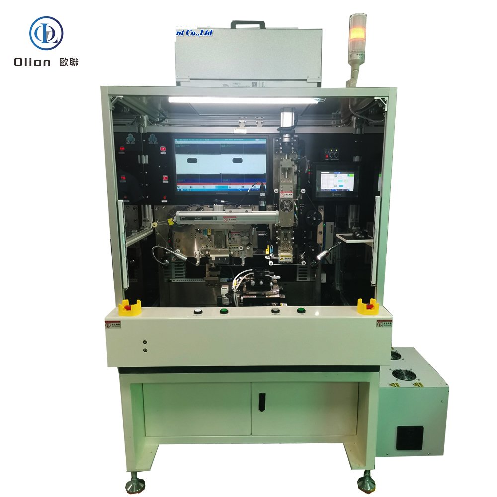
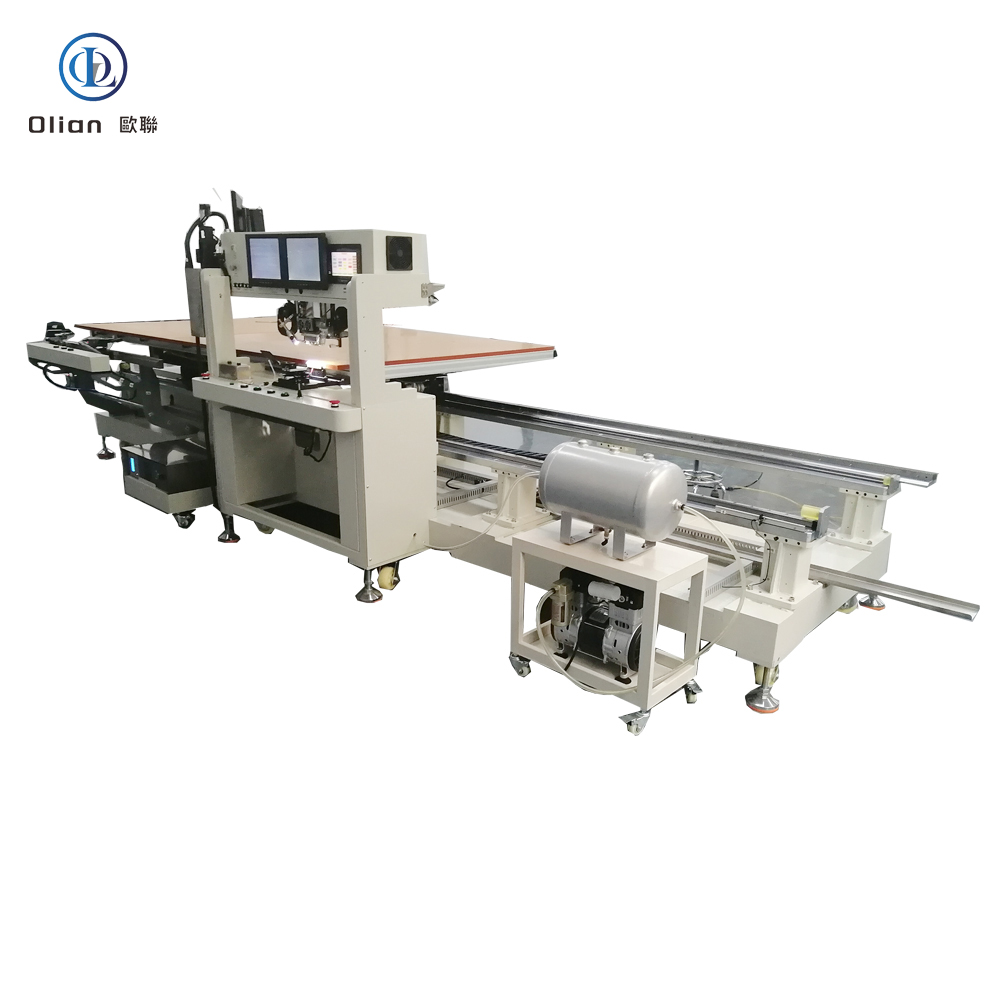
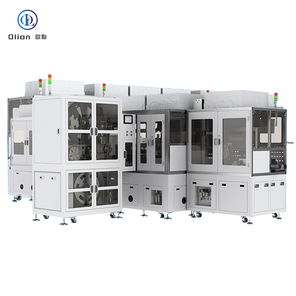
An OLB bonding machine is the hidden hero behind every large-screen TV, laptop and automotive display you see today. OLB—Outer Lead Bonding—is the final assembly step in which the “outer leads” of a TAB (Tape Automated Bonding) or COF (Chip-On-Film) package are attached to a glass panel or PCB so that signals from the driver IC can reach the outside world. The equipment that performs this micro-weld must deliver sub-micron alignment, single-degree thermal control and kilogram-level force accuracy—all in under three seconds. This article explains every angle of the technology for “OLB bonding machine”, “OLB bonder”, “outer lead bonding equipment”, “TAB OLB bonding”, “COF OLB bonding”, “LCD OLB repair machine” and dozens more high-value keywords.


OLB is the acronym for “Outer Lead Bonding”. In a display module the driver IC is first mounted on a flexible polyimide tape (TAB) or on a continuous reel (COF). The inner leads of that tape are bonded to the IC bumps in an earlier process called ILB (Inner Lead Bonding). The outer leads—fine copper traces that fan out beyond the IC—must now be connected to the display glass (for source drivers) or to a rigid PCB (for gate drivers). The machine that executes this final link is called an OLB bonding machine. It uses anisotropic conductive film (ACF) to create thousands of vertical contacts while remaining insulating laterally, then folds the tail 180° so the IC disappears behind the panel, shrinking the bezel to under 1 mm.
COG (Chip-On-Glass) works well for phones, but for 32″-120″ TVs the driver ICs generate too much heat to be parked on the glass. COF (Chip-On-Film) brings the IC onto a flex tail, but the tail must still exit sideways before folding—OLB is the step that actually welds that tail to the glass or PCB. The process is repair-friendly: a defective tail can be removed and rebonded without scrapping the entire panel. Automotive Tier-1 suppliers also rely on OLB because it survives 1,000 h of 85 °C/85 % RH and −40 °C to +105 °C thermal cycling required
Bonding Head: Titanium alloy, diamond-lapped to 0.3 µm flatness, DLC-coated for anti-stick, lasts 300,000 cycles.
Pulse Heater: 800 W cartridge, embedded K-type thermocouple, ramp 200 °C/s, overshoot < 0.5 °C.
Force Actuator: Voice-coil or servo motor, 24-bit encoder, 0.1 N resolution, 2 ms response; active gravity cancellation for 0.4 mm glass.
Vision System: 12 MP global-shutter CMOS, telecentric lens, coaxial + side LED, sub-pixel edge detection repeatable to 0.2 µm.
Motion Stage: Cross-roller bearings, 0.05 µm linear encoder, servo feedback at 20 kHz, granite base with passive vibration isolation.
ACF Feed Unit: Stepper-driven, tungsten-steel cutter, anti-static vacuum, waste take-up spool, splice sensor for uninterrupted production.
Real-time Linux kernel guarantees < 1 ms jitter; PID temperature loop updated at 10 kHz.
Recipe manager encrypts parameters—temperature, pressure, time, ramp rate—per product QR code.
AI vision self-learns new pad patterns from panel vendors, reducing setup time 70 %.
MES interface via OPC-UA uploads cycle data, resistance values, and images for full traceability.
Cloud dashboard predicts heater degradation and schedules maintenance before scrap occurs.
LCD & OLED TV: 32″-120″ 4K/8K panels—bonding source COF tails to glass edge, gate COF tails to PCB.
Automotive: Curved instrument clusters, 15 inch OLED infotainment, head-up displays—passing 1,000 h 85 °C/85 % RH.
Medical: Surgical monitors, portable ultrasound, wearable patches—biocompatible polyimide, ISO 13485 traceability.
Industrial & Military: Avionics displays, factory HMI panels, rugged handhelds—shock, altitude, fungus per MIL-STD-810.
OLB bonding machine, OLB bonder, outer lead bonding equipment, TAB OLB bonding, COF OLB bonding, LCD OLB repair machine, OLED OLB bonding, 8K OLB bonding, 100 inch OLB bonding, automotive OLB bonding, medical OLB bonding, pulse heat OLB bonding, constant temperature OLB bonding, ACF OLB bonding, AI vision OLB bonding, IoT OLB bonding machine, China OLB bonding machine, automatic OLB bonder, OLB bonding accuracy 1 micron, OLB bonding temperature 220 C, OLB bonding pressure 1 MPa, vertical conduction horizontal insulation, lead-free OLB bonding, ROHS compliant OLB bonding.
Copper-Core ACF: Cu-Ag particles cut material cost 50 % while keeping < 20 mΩ contact resistance.
Green Refrigerants: Closed-loop cooling replaces water with R1234ze, reducing carbon footprint 30 %.
AI-Driven Profiles: Neural networks auto-optimize temperature ramps for each polyimide type, pushing yield to 99.9 %.
Cold-Laser Fold Assist: Femtosecond laser pre-scores the coverlay, enabling 90° fold with 50 µm radius and zero trace damage.
Servo-Hydraulic Hybrid: Delivers 80 kg force for 100″ TV OLB tails while keeping 1 µm position accuracy.
Dual-Head Systems: Parallel bonding of source and gate OLBs doubles throughput without extra floor space.
An OLB bonding machine is no longer a niche display tool—it is the critical gateway between microscopic IC bumps and macroscopic screen signals. By mastering sub-micron alignment, single-degree thermal control and real-time force feedback, the latest OLB bonders deliver sub-3-second cycles with 99.9 % yield and full Industry 4.0 traceability. Whether you are a display OEM chasing 0.9 mm bezels, an automotive Tier-1 qualifying 100-inch curved clusters, or a repair center reworking $300 TV panels, investing in an AI-enhanced, IoT-connected OLB bonding platform future-proofs your process.
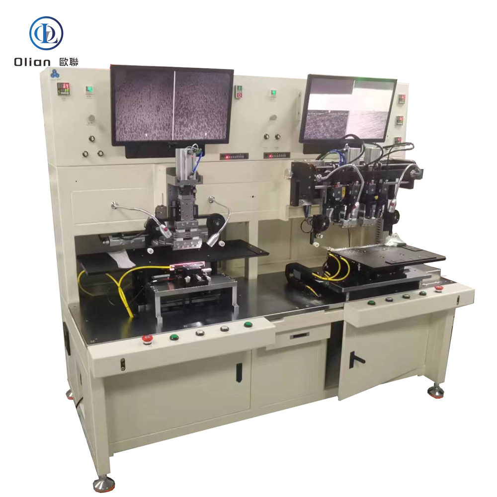
A FOB bonding machine—short for Flex-On-Board or Film-On-Board—is the critical link between a floppy polyimide tail and a rigid printed-circuit board. It grabs a flexible printed circuit (FPC), aligns it to a PCB within a single micron, and welds the copper traces together with anisotropic conductive film (ACF) in under three seconds. The result is a vibration-proof, heat-proof, lead-free joint that survives −40 °C automotive winters and +105 °C engine-bay summers. This guide walks through physics, hardware, software, specs, applications, trends, and maintenance rank you for “FOB bonding machine”, “FOB bonder”, “FPC to PCB bonding”, “ACF FOB machine”, “automotive FOB bonding”,
A FOB bonding machine is a servo-driven, vision-guided, pulse-heat press that laminates anisotropic conductive film onto a PCB, then bonds a flexible printed circuit (FPC) or chip-on-film (COF) tail to that PCB with micron-level accuracy. The film contains nickel or gold-coated spheres that conduct only vertically, giving thousands of simultaneous contacts while remaining insulated laterally. The same platform reworks defective boards by removing the old ACF and rebonding a new tail, saving a $200 automotive cluster or a $150 tablet mainboard.
Rigid PCBs cannot fold; wire harnesses fail after 10,000 vibration cycles; connectors add height and cost. FOB eliminates all three pain points by folding a 25 µm polyimide tail 180° with 0.2 mm radius and locking it to the PCB in a 2-second cycle. Automotive Tier-1 suppliers prefer FOB because it passes AEC-Q100 Grade 0 (−40 °C to +150 °C) without a single connector contact. Consumer OEMs love the 0.9 mm board-edge profile that enables edge-to-edge displays.
Bonding Head: Titanium alloy, diamond-lapped to 0.3 µm flatness, DLC-coated for anti-stick, lasts 300,000 cycles.
Pulse Heater: 800 W cartridge, embedded K-type thermocouple, ramp 200 °C/s, overshoot < 0.5 °C.
Force Actuator: Voice-coil or servo motor, 24-bit encoder, 0.1 N resolution, 2 ms response; active gravity cancellation for 25 µm PCBs.
Vision System: 12 MP global-shutter CMOS, telecentric lens, coaxial + side LED, sub-pixel edge detection repeatable to 0.2 µm.
Motion Stage: Cross-roller bearings, 0.05 µm linear encoder, servo feedback at 20 kHz, granite base with passive vibration isolation.
ACF Feed Unit: Stepper-driven, tungsten-steel cutter, anti-static vacuum, waste take-up spool, splice sensor for uninterrupted production.
Real-time Linux kernel guarantees < 1 ms jitter; PID temperature loop updated at 10 kHz.
Recipe manager encrypts parameters—temperature, pressure, time, ramp rate—per product QR code.
AI vision self-learns new pad patterns from PCB suppliers, reducing setup time 70 %.
MES interface via OPC-UA uploads cycle data, resistance values, and images for full traceability.
Cloud dashboard predicts heater degradation and schedules maintenance before scrap occurs.
Consumer Electronics: Smartphone mainboard, tablet battery flex, laptop keyboard backlight, smartwatch heart-rate sensor.
TV & Signage: 32″–100″ 4K/8K LCD, OLED, mini-LED—bonding source COF tails to main PCB.
Automotive: Curved instrument clusters, 15 inch OLED infotainment, head-up displays, camera modules—passing 1,000 h 85 °C/85 % RH.
Medical: Surgical hand-piece flex, portable ultrasound mainboard, wearable ECG patch—biocompatible polyimide, ISO 13485 traceability.
Industrial & Military: Avionics displays, factory HMI panels, rugged handhelds—shock, altitude, fungus per MIL-STD-810.
FOB bonding machine, FOB bonder, FPC to PCB bonding, ACF FOB machine, flex-on-board bonding, Film-on-board bonder, pulse heat FOB bonding, constant temperature FOB bonding, automotive FOB bonding, medical FOB bonding, 0.2 mm fold radius FOB, 25 µm polyimide FOB bonding, 100 inch FOB bonding, AI vision FOB bonding, IoT FOB bonding machine, China FOB bonding machine, automatic FOB bonder, FOB bonding accuracy 1 micron, FOB bonding temperature 200 C, FOB bonding pressure 1 MPa, vertical conduction horizontal insulation, lead-free FOB bonding, ROHS compliant FOB bonding.
Copper-Core ACF: Cu-Ag particles cut material cost 50 % while keeping < 20 mΩ contact resistance.
Green Refrigerants: Closed-loop cooling replaces water with R1234ze, reducing carbon footprint 30 %.
AI-Driven Profiles: Neural networks auto-optimize temperature ramps for each polyimide type, pushing yield to 99.9 %.
Micro-LED Bridge: Same FOB platform bonds 20 µm × 20 µm micro-LED dies onto flexible PCBs.
Cold-Laser Fold Assist: Femtosecond laser pre-scores the coverlay, enabling 90° fold with 50 µm radius and zero trace damage.
Servo-Hydraulic Hybrid: Delivers 80 kg force for 100″ TV FOB tails while keeping 1 µm position accuracy.
A FOB bonding machine is no longer a niche flex-to-board press—it is the critical enabler for foldable smartphones, zero-bezel TVs, curved automotive clusters, and biocompatible medical wearables that define 2025 consumer expectations. By mastering sub-micron alignment on 25 µm polyimide, pulse-heat control within half a degree, and real-time force feedback, the latest FOB bonders deliver sub-3-second cycles with 99.9 % yield and full Industry 4.0 traceability. Whether you are a display OEM chasing a 0.9 mm chin, an automotive Tier-1 qualifying radar modules, or a medical start-up prototyping flexible patches, investing in an AI-enhanced, IoT-connected FOB bonding platform future-proofs your process.
An IC bonding machine is the beating heart of every microelectronic package you touch—whether it’s the OLED display in your foldable phone, the radar sensor in your car, or the memory stack in your laptop. It is the precision system that places a bare silicon die onto a substrate—glass, flex, PCB, or lead-frame—and then creates permanent electrical joints by thermo-compression, ultrasonic, or eutectic means. Keywords”IC bonding machine”, “IC die bonder”, “wire bonding machine”, “eutectic IC bonder”, “flip-chip bonder”, “COG bonding machine”, “COB bonding machine”, “thermosonic bonding”, “ultrasonic wire bonder.
An IC bonding machine is a high-precision mechatronic platform that picks up a bare integrated-circuit die from a wafer, waffle pack, or gel-pak, places it with micron accuracy onto a target substrate, and then forms electrical and mechanical joints by one of three core methods: wire bonding (thermosonic or ultrasonic), flip-chip thermo-compression, or eutectic/solder reflow. Modern platforms achieve ±1 µm placement accuracy, ±0.3 ° angular repeatability, and 0.1 g force resolution on die sizes from 0.25 mm × 0.25 mm to 25 mm × 25 mm. The same machine also reworks defective packages by removing the old die and rebonding a new one.
Gold or copper bumps on the die must touch copper pads on the substrate. At room temperature the native oxide layer prevents reliable contact. Thermosonic wire bonding uses 150 °C stage heat plus 60 kHz ultrasonic energy to break the oxide and form Au-Al intermetallics. Flip-chip thermo-compression applies 200 °C and 1 MPa to deform gold or solder bumps, creating cold-weld joints. Eutectic bonding raises temperature above 280 °C so Au-Sn or Cu-Sn forms a liquid phase that solidifies into a void-free joint. Each method demands closed-loop temperature, force, and time control to within 1 %.
Die Bond Head: Ceramic or titanium collet, 0.1 µm run-out, vacuum channel optimized for 50 µm thin die.
Ejector Stage: Triple-needle system with 1 µm z-repeatability, adjustable stroke 0–3 mm, anti-crumple software.
Linear Motors: Iron-less design, 5 g acceleration, 0.05 µm encoder resolution, backlash-free for < 1 ms settling.
Force Sensor: Strain-gauge or optical, 0.1 g resolution, 10 kHz bandwidth, real-time overload protection.
Temperature Stack: Pulse-heated stage 25–500 °C, ramp 100 °C/s, uniformity ±1 °C across 300 mm wafer.
Vision Trains: Dual 12 MP cameras, telecentric lenses, coaxial + side LED, AI edge detection repeatable to 0.2 µm.
Wire Feed System: Ultrasonic cleaner, flame-off electrode, vacuum tail collector, gold or copper wire 18–75 µm diameter.
Real-time Linux or RTX kernel guarantees < 500 µs jitter; PID loops updated at 20 kHz.
Recipe manager encrypts parameters—temperature profile, force ramp, ultrasonic power—per product QR code.
MES interface via OPC-UA uploads die ID, XY coordinates, bond force, and wire-pull data for full traceability.
AI predictor analyses capillary wear and forecasts ball-shape drift 200 bonds ahead, cutting unplanned downtime 30 %.
Remote VPN allows OEM engineers to debug without on-site visit, saving travel cost and CO₂ footprint.
Consumer Electronics: Smartphone OLED driver, tablet touch MCU, laptop power management IC, memory stack in SSD.
TV & Display: COG bonding of source drivers on 8K LCD/mini-LED panels; COF bonding on curved OLED TVs.
Automotive: Radar MMIC, camera ISP, LED headlamp driver, infotainment processor—qualified to AEC-Q100 Grade 0 (−40 °C to +150 °C).
Medical: MEMS pressure sensors, hearing-aid DSP, catheter imaging chip—biocompatible epoxy, ISO 13485 traceability.
Industrial & Aerospace: FPGA on ceramic substrate, power GaN dies, RF amplifiers in 5G base stations, satellites, and defense systems.
IC bonding machine, IC die bonder, wire bonding machine, thermosonic wire bonder, ultrasonic wire bonder, eutectic IC bonding machine, flip-chip bonder, COG bonding machine, COB bonding machine, TAB bonding machine, ACF IC bonding, pulse-heat IC bonding, 1 micron placement accuracy, 12 inch wafer bonding, memory stack bonding, GaN die bonding, automotive IC bonding, medical MEMS bonding, 5G RF bonding, China IC bonding machine, automatic IC bonder, IC bonding temperature 200 C, IC bonding force 1 MPa, gold wire bonding, copper wire bonding, aluminum wire bonding.
Hybrid Bonders: Single platform switches between wire, flip-chip, and eutectic modes in < 5 min, cutting cap-ex by 40 %.
AI-Driven Calibration: Neural networks auto-learn capillary wear and adjust ultrasonic power, pushing yield to 99.99 %.
Copper Wire Migration: 100 % Cu wire replaces gold, cutting material cost 90 % while maintaining < 30 mΩ resistance.
Cold-Laser Clean: Femtosecond laser removes organic contamination at room temperature, enabling 120 °C low-temp bonds for flexible OLED.
Green Factory: Closed-loop chillers and regenerative brakes on linear motors cut energy per bond 25 %.
Heterogeneous Integration: Same bonder stacks logic, memory, and RF chiplets using hybrid bonding (oxide fusion) with < 100 nm alignment.
An IC bonding machine is no longer a single-purpose press—it is the atomic-level gateway between nanometer transistors and millimeter-scale packages. By mastering sub-micron placement, millisecond thermal control, and real-time force feedback, the latest IC bonders deliver 6-wire-per-second speed, 99.99 % yield, and full Industry 4.0 traceability. Whether you are a display OEM stacking 8K drivers, an automotive Tier-1 qualifying radar MMICs, or a medical start-up packaging MEMS sensors, investing in an AI-enhanced, IoT-connected IC bonding platform future-proofs your process.