TFT displays manufacturing glass cutting laminating bonding dispensing assembling testing packing processes detailed introduction to each process and equipment situation:
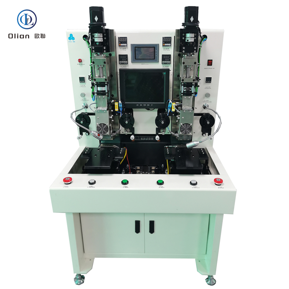
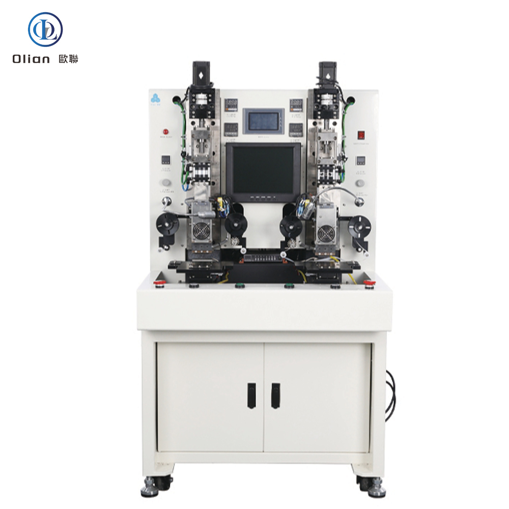
Anisotropic Conductive Film ApplicationsMobile Phones Tablets and Industrial Control Products Whole Line Solution for TFT DisplaysACF Bonding Parts and AccessoriesMid Size 7-17 Inch Vehicle Display and Notebook Whole Line SolutionFOG FOP FOF FOB T-FOG FPC Flex Cable Bonding MachineCOF COP COG IC PRE BONDERIC MIAN BONDERFOG FOP FOF FOB T-FOG FPC Flex Cable Bonding Machinepolarizer laminating machineFOG FOP FOF FOB T-FOG FPC Flex Cable Bonding Machine7-12INCH long head FOG FOB bonding machine
1. Cutting Process
Process Introduction: In this stage, large – sized TFT – LCD glass substrates or polarizing plates are cut into smaller pieces according to the required dimensions of the display module.
High – precision cutting is crucial to ensure the edges of the cut pieces are smooth and free of cracks or defects, which affects the quality and yield of subsequent processes.
Equipment – Cutting Machine: Equipped with high – precision cutting blades or laser cutting heads, the cutting machine can accurately cut glass substrates and polarizing plates. Its positioning system ensures precise alignment of the cutting lines with the preset dimensions. Some advanced cutting machines also feature automatic feeding and discharging functions to improve production efficiency.
2. SB AOI (Automated Optical Inspection) Process
Process Introduction: This process uses automated optical inspection equipment to detect defects on the surface of the TFT – LCD panel after cutting, such as scratches, particles, and polarity direction.
It helps to identify and eliminate defective products early in the production line, reducing production costs and improving overall product quality.
Equipment – AOI Machine: The AOI machine is equipped with high – resolution cameras and advanced image processing software. It can quickly capture images of the panel surface and compare them with the standard template to identify defects.
Its inspection speed can be adjusted according to the size and resolution of the panel, and it has a high detection accuracy rate.
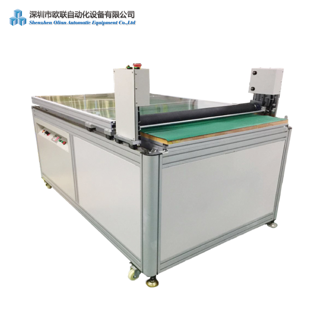
3. POL Attach Process
Process Introduction: Polarizing plates are thin layers that allow light to pass through either horizontally or vertically. In this process, the polarizing plate is bonded to the surface of the TFT – LCD panel. The bonding must be accurate and free of bubbles or wrinkles to ensure the display effect of the LCD screen.
Equipment – POL Attaching Machine: The POL attaching machine has a high – precision alignment system to precisely position the polarizing plate on the panel. Its pressing mechanism ensures uniform pressure during bonding, and the heating system helps the adhesive cure, enhancing the bonding strength between the polarizing plate and the panel.
4. Autoclave Process
Process Introduction: The autoclave process is used to further strengthen the bonding between the polarizing plate and the panel. By applying high – temperature and high – pressure conditions, the air bubbles and impurities within the bonding layer are eliminated, improving the bonding quality and reliability of the polarizing plate.
Equipment – Autoclave Machine: The autoclave machine is a sealed pressure vessel that can precisely control temperature and pressure parameters. It evenly heats and pressurizes the panels placed inside, ensuring uniform treatment of each panel. Its control system can set different temperature and pressure curves according to the characteristics of the panels and polarizing plates.
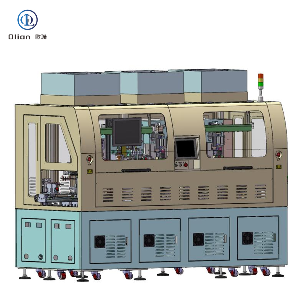
5. Bonding Process (LD/EC+COG+FOG+Bonding AOI+Glue dispenser+ULD)
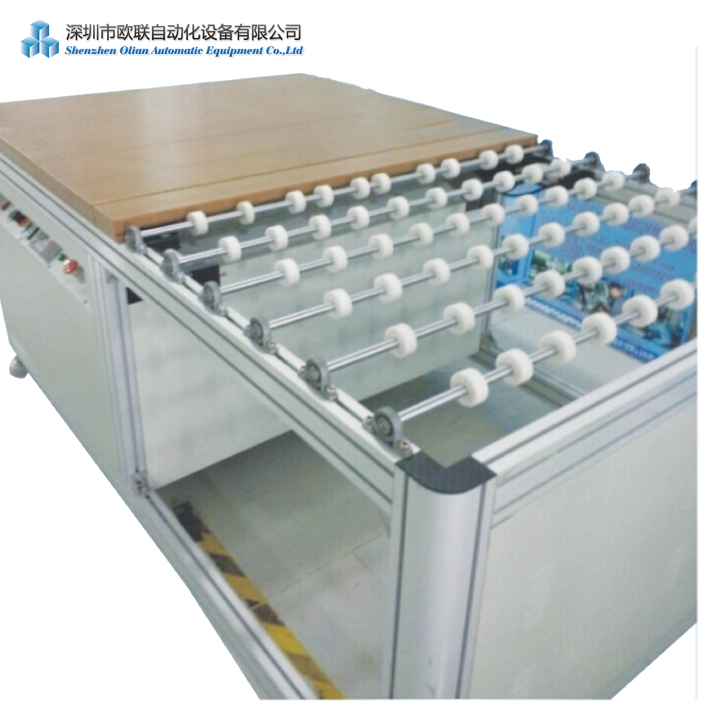
LD (Glass Loading) Process:
Glass loading is the process of placing the cut glass substrates into designated fixtures or carriers to prepare them for subsequent processes such as electronic cleaning and bonding. It ensures the glass substrates are properly positioned and secured for further processing.
Equipment – Glass Loading Machine:
The glass loading machine is designed to handle glass substrates with care. It has a precise positioning system to place the glass substrates into the fixtures accurately. The machine may also feature automated arms or conveyors to transport the glass substrates efficiently while minimizing manual handling and potential damage.
EC (Electronic Cleaning) Process:
Electronic cleaning is used to remove contaminants such as dust, organic residues, and ions from the surface of the glass substrates or polarizing plates. This helps improve the bonding quality and reliability in subsequent processes, preventing issues like poor adhesion or electrical shorts.
Equipment – Electronic Cleaning Machine:
The electronic cleaning machine typically uses a combination of ultrasonic waves, deionized water, and chemical cleaning agents to thoroughly clean the glass substrates or polarizing plates. It has a closed cleaning chamber to prevent re – contamination and a drying system to quickly dry the cleaned substrates after cleaning.
COG (Chip – on – Glass) Process:
The driver IC is directly bonded to the glass substrate of the TFT – LCD panel. This process is characterized by high precision and small bonding area, offering advantages such as fast production speed and good electrical performance.
Equipment – COG Bonding Machine: The COG bonding machine uses a high – precision alignment system to accurately position the driver IC relative to the glass substrate. Its heating and pressing mechanism ensures a stable connection between the driver IC and the glass substrate. The machine also has a vision system for precise alignment and a temperature – and – pressure control system to ensure bonding quality.
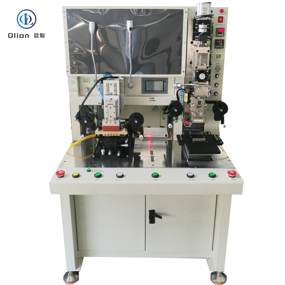
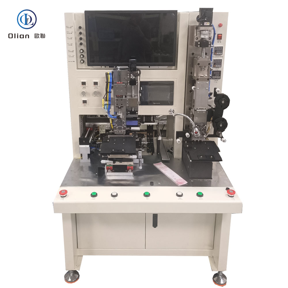
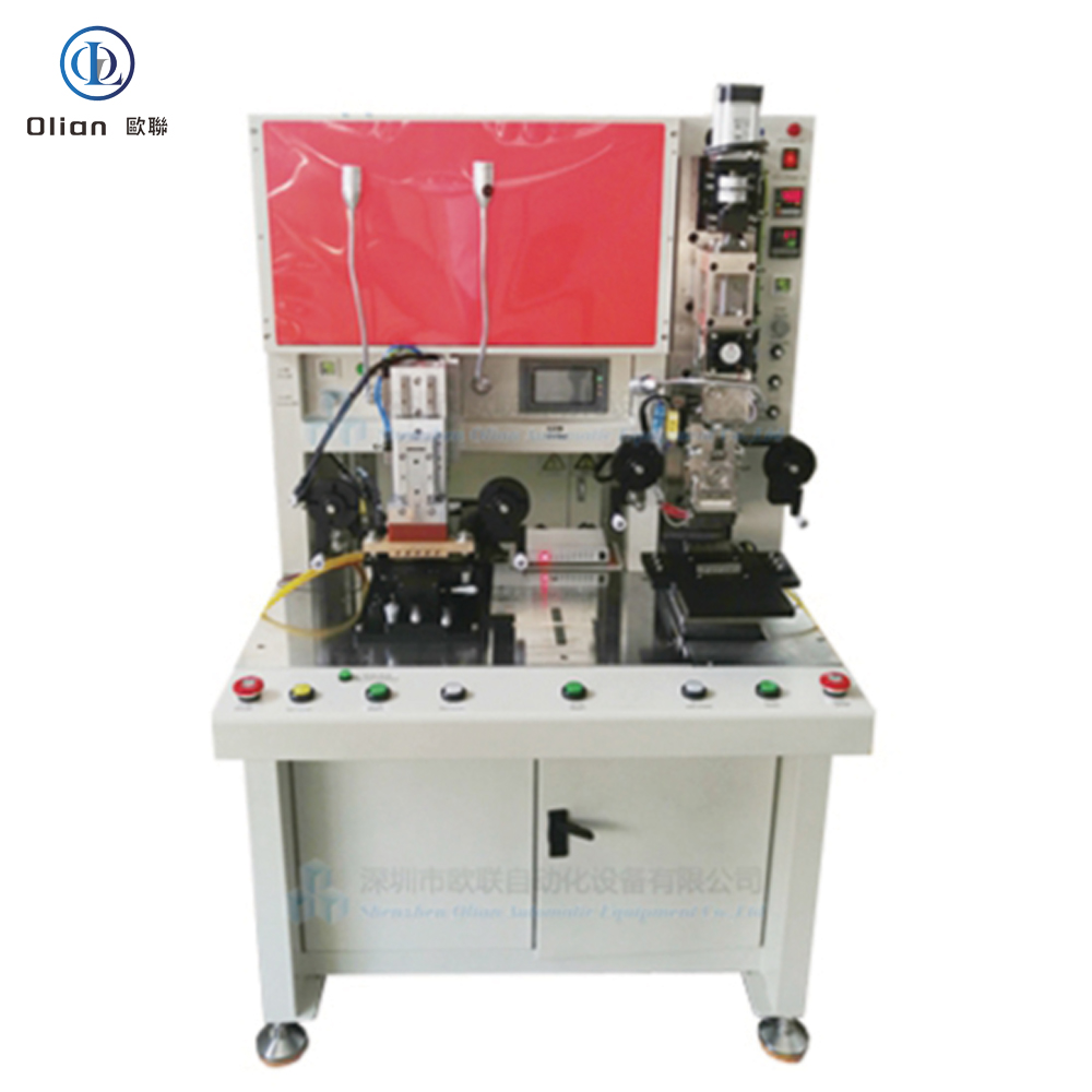
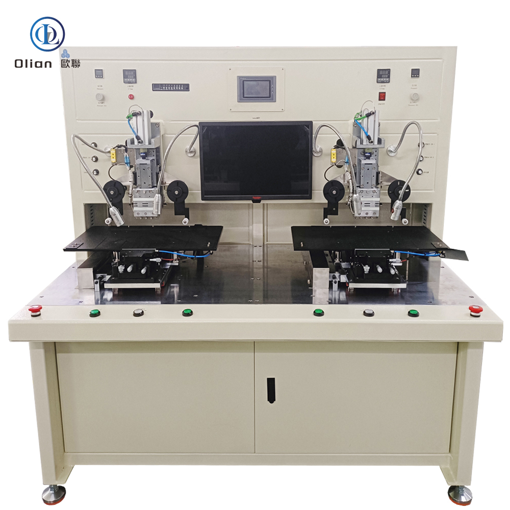
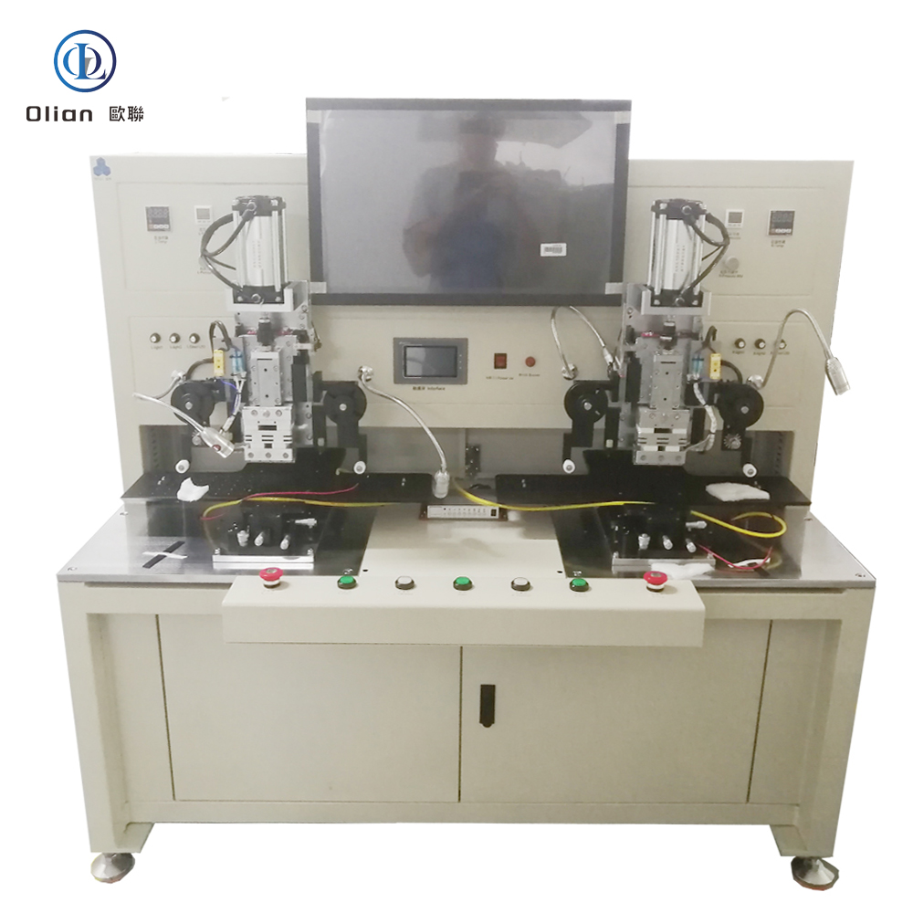
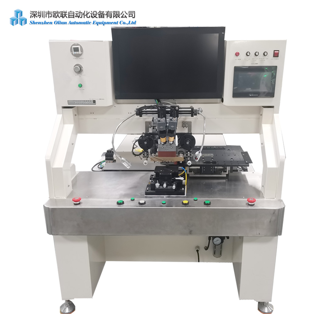
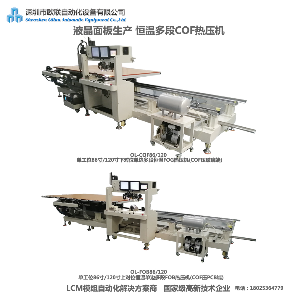
FOG (Film – on – Glass) Process:
The driver IC is first bonded to a flexible film and then connected to the TFT – LCD panel. It offers better flexibility and reliability, suitable for lightweight and thin display devices.
Equipment – FOG Bonding Machine: The FOG bonding machine is designed to handle flexible films and perform high – precision bonding. It has a complex structure and advanced to technology ensure reliable connections between the driver IC and the panel. Its alignment system accurately positions the flexible film and driver IC on the panel.
Bonding AOI Process:
After the bonding process, automated optical inspection is used to detect defects in the bonding quality, such as misalignment, missing bonds, and insufficient bonding. This helps to promptly identify and correct bonding issues, improving production yield.
Equipment – Bonding AOI Machine: The bonding AOI machine uses high – resolution cameras and advanced image processing software to capture images of the bonding area and compare them with the standard template. It can accurately detect various bonding defects and has a fast inspection speed, capable of meeting the high – speed production requirements of the production line.
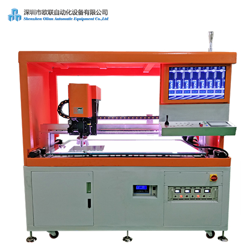
Glue Dispensing Process:
Adhesive is applied to the bonding area to enhance bonding the strength and reliability between the driver IC and the panel. The glue dispenser must ensure precise glue – dispensing quantity and uniform glue – dispensing.
Equipment – Glue Dispensing Machine: The glue dispensing machine has a high – precision dispensing system that can accurately control the glue – dispensing quantity and pattern. Its dispensing nozzle can move precisely to dispense adhesive on the designated bonding area. The machine can also adjust the glue – dispensing parameters according to different adhesives and bonding requirements.
ULD (Under – Layer Dispensing) Process:
This process applies an under – layer adhesive to the bonding area to further enhance the bonding strength and reliability. It also helps to prevent moisture and impurities from invading the bonding area, improving the product’s stability and reliability.
Equipment – ULD Machine: The ULD machine is similar to the glue dispensing machine in structure but specializes in applying under – layer adhesives. It can accurately dispense under – layer adhesives on the bonding area and has a heating and curing system to rapidly cure the adhesive, improving production efficiency.
6. PWB (Printed Wiring Board) Process
Process Introduction: In this process, the printed wiring board is assembled and connected to the TFT – LCD panel. The PWB serves as the carrier of the electrical circuit, connecting various components of the display module and enabling signal transmission and power supply.
Equipment – PWB Assembly Machine: The PWB assembly machine includes functions such as component placement and soldering. It uses high – precision placement heads to accurately position components on the PWB and employs automated soldering equipment to ensure reliable soldering connections. The machine also has an inspection system to detect defects in the PWB assembly.
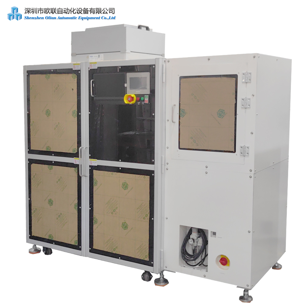
7. Oven Process
Process Introduction: The oven process is used to cure adhesives or other materials used in the bonding and assembly processes. By heating, the adhesives can fully cure, enhancing bonding strength and reliability. It also helps to remove residual solvents and impurities, improving product quality.
Equipment – Oven: The oven has a temperature control system that can precisely regulate the temperature and heating time according to different process requirements. It provides a uniform heating environment to ensure uniform curing of the adhesives on each panel. The oven also has a ventilation system to timely exhaust volatile substances during the heating process.
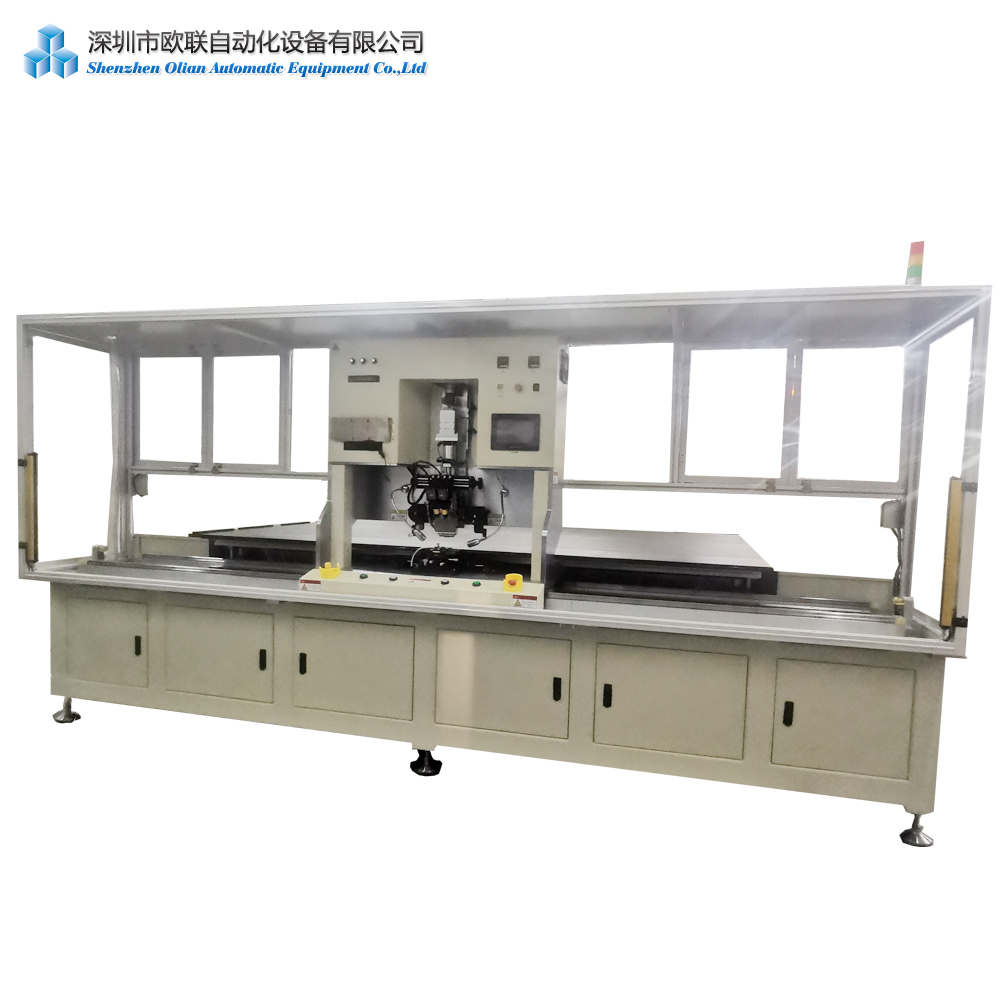
8. Optical Bonding Process
Process Introduction: Optical bonding is the process of filling the gap between the TFT – LCD panel and the cover glass with an optical adhesive. This eliminates air gaps between the two, reducing light reflection and refraction, improving display clarity and brightness, and enhancing the product’s resistance to external impacts and vibrations.
Equipment – Optical Bonding Machine: The optical bonding machine has a high – precision dispensing system to accurately dispense optical adhesive between the panel and the cover glass. Its pressing mechanism ensures uniform pressure during bonding, and the machine is equipped with a degassing system to remove bubbles within the adhesive. Some optical bonding machines also have a UV curing system to rapidly cure the adhesive using ultraviolet light.
9. Auto Clave Process
Process Introduction: Similar to the autoclave process in the POL attach stage, this process further strengthens the bonding between the optical adhesive and the panel and cover glass through high – temperature and high – pressure conditions. It eliminates bubbles and impurities within the bonding layer, improving the bonding quality and reliability.
Equipment – Autoclave Machine: The autoclave machine used in this stage is similar to that in the POL attach stage but may have different parameter settings. It can precisely control the temperature and pressure to meet the requirements of the optical bonding process. Its control system can set different temperature and pressure curves according to the characteristics of the optical adhesive and the panels.
10. Backlight Assembly Process
Process Introduction: The backlight assembly process involves assembling the backlight module, including components such as the light guide plate, reflective film, diffusion film, and prism film. The backlight module provides uniform backlight for the TFT – LCD panel, ensuring accurate display of images. The assembly of the backlight module must be precise to ensure uniform light distribution and high brightness.
Equipment – Backlight Assembly Machine: The backlight assembly machine has functions such as automatic placement and lamination. It accurately positions the components of the backlight module and uses lamination technology to bond them together. The machine can adjust the placement parameters according to the size and thickness of the backlight module components to ensure assembly quality.
11. FI AOI (Final Inspection AOI) Process
Process Introduction: As the final stage of the production line, FI AOI conducts a comprehensive optical inspection of the assembled TFT – LCD display module. It detects defects such as display abnormalities, brightness unevenness, and pixel defects to ensure the product meets quality standards before delivery.
Equipment – FI AOI Machine: The FI AOI machine is equipped with high – resolution cameras and advanced image processing software. It can capture images of the display module from multiple angles and comprehensively evaluate the display quality. Its inspection accuracy is high, capable of detecting even minor defects. The machine also has a data analysis system to statistically analyze the defect data of the product, providing a basis for quality improvement.
12. Aging Process
Process Introduction: The aging process subjects the TFT – LCD display module to prolonged operation under specific conditions (e.g., temperature, humidity, and voltage) to simulate long – term usage scenarios. This helps identify potential reliability issues, such as pixel aging and circuit instability, ensuring the product’s reliability and stability during actual use.
Equipment – Aging Chamber: The aging chamber provides a stable and controllable environment, capable of regulating temperature and humidity and offering adjustable voltage and current. It can simultaneously age multiple display modules and has a monitoring system to real – time track the operating status of the modules during aging. Once abnormalities are detected, the system automatically alerts and takes protective measures.
13. Vacuum Packing Process
Process Introduction: Vacuum packing is used to remove air from the packaging bag of the TFT – LCD display module, reducing the volume of the product and preventing oxidation and moisture damage during transportation and storage. It also offers certain protection against external impacts.
Equipment – Vacuum Packing Machine: The vacuum packing machine has a vacuum chamber and a sealing system. It creates a vacuum environment within the chamber to extract air from the packaging bag and then seals the bag to ensure airtightness. The machine can adjust the vacuum degree and sealing parameters according to the size and material of the packaging bag to guarantee vacuum packing quality.
14. Carton Packaging Process
Process Introduction: In this final stage, the vacuum – packed TFT – LCD display module is placed into a carton along with necessary accessories and documentation. The carton packaging provides further protection for the product during transportation and storage, preventing damage from external impacts and facilitating storage and transportation.
Equipment – Carton Packaging Machine: The carton packaging machine has functions such as automatic carton forming, loading, and sealing. It can automatically form cartons according to the size of the product, load the product and accessories into the carton, and seal it. The machine can also print relevant information on the carton, such as product specifications and barcodes.
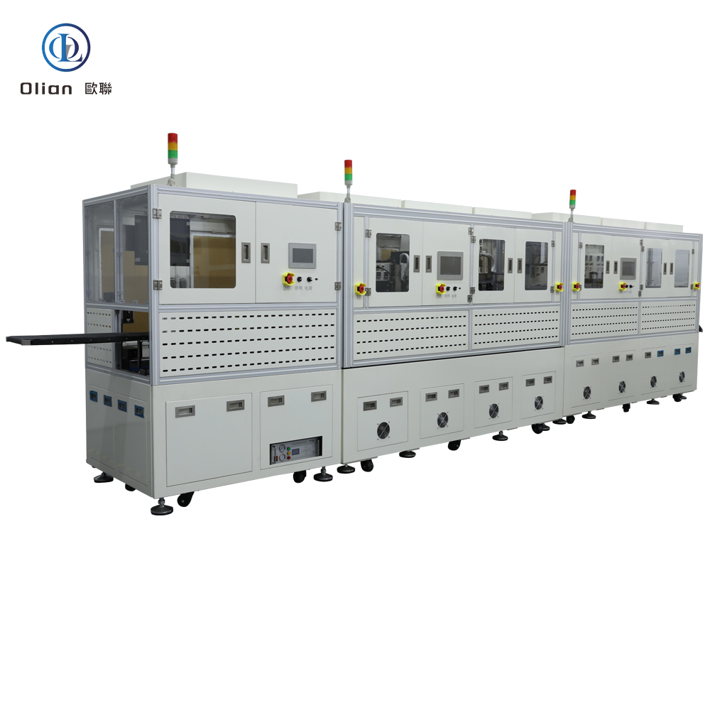
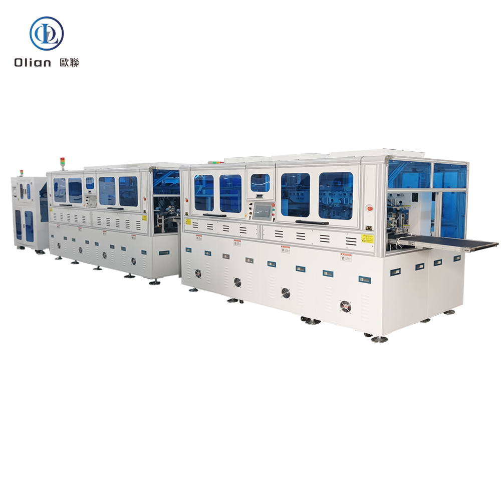
Display Screen Production lines,In the dynamic world of electronics manufacturing, Shenzhen Olian offers a comprehensive range of solutions designed to meet the high-precision requirements of modern display and electronic component production. From flexible screen glue field production to intelligent locomotive and notebook product lines, our solutions are tailored to enhance efficiency, reliability, and quality.
ACF Bonding Parts and AccessoriesMobile Phones Tablets and Industrial Control Products Whole Line Solution for TFT DisplaysSmart Wear LCD OLED Bonding Production Whole Line SolutionCOF COP COG IC PRE BONDERIC MIAN BONDERFOG FOP FOF FOB T-FOG FPC Flex Cable Bonding Machine
High-Level Flexible Screen Glue Field Production Solutions
Our high-level flexible screen glue field production solutions are designed for the precise application of adhesives in the production of flexible OLED displays. These solutions support a combination of COG/FOG, COF/FOF, and COP/FOP processes, ensuring high-quality connections and efficient production
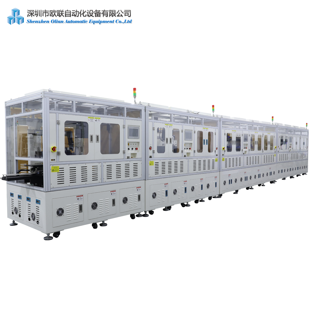
Intelligent Locomotive and Notebook Product Line Solutions
For the manufacturing of intelligent locomotive and notebook products, Shenzhen Olian provides advanced production line solutions. These solutions are designed to handle the specific requirements of these products, ensuring high precision and reliability in every step of the manufacturing process
Display Product Line Solutions
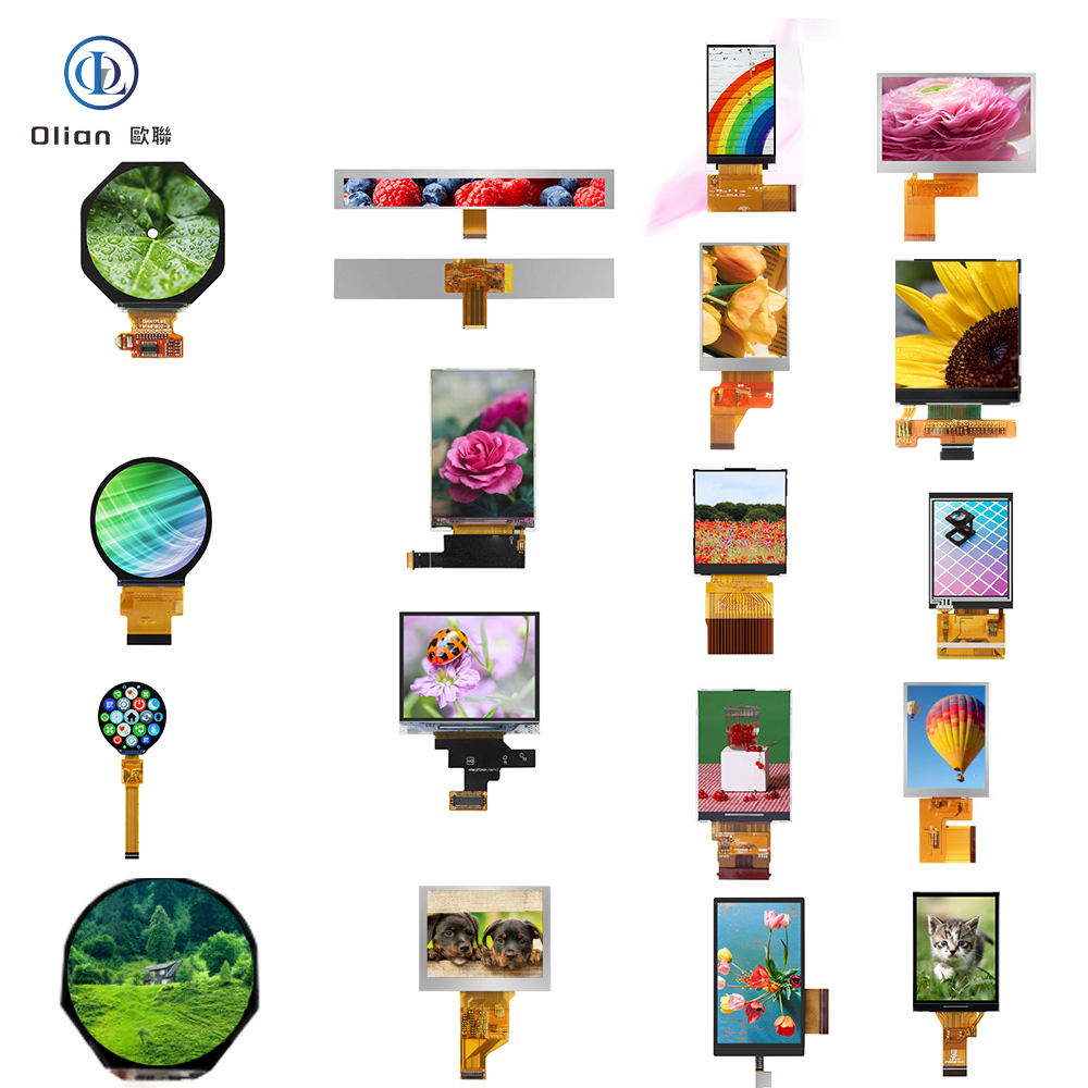
Our display product line solutions cover a wide range of processes, including bonding, laminating, and dispensing. These solutions are suitable for various display technologies such as LCD, OLED, Mini LED, and Micro LED. They are designed to ensure high-quality connections and efficient production, making them ideal for manufacturers of smartphone screens, wearable devices, large TV panels, and advanced OLED displays
Commercial Display Screen Flexible Bonding Production Line Solutions
For commercial display screens, Shenzhen Olian offers flexible bonding production line solutions. These solutions are designed to handle the specific requirements of large-format displays, ensuring high precision and reliability. They are suitable for a variety of applications, including advertising displays, public information displays, and industrial control systems
Electronic Paper Line Solutions
Our electronic paper line solutions include laminating, bonding, and dispensing field line solutions. These solutions are designed to meet the high-precision requirements of E-paper displays, ensuring high-quality connections and efficient production. They are suitable for a variety of applications, including e-readers, smart labels, and public information displays
Backlight Leading, Laminated Film, Shading, and Wrapping Line Equipment Solutions
Shenzhen Olian provides comprehensive solutions for backlight leading, laminated film, shading, and wrapping line equipment. These solutions are designed to ensure high precision and reliability in the production of displays, making them ideal for manufacturers of smartphone screens, large TV panels, and other advanced displays
Fingerprint Module Under the Screen Bond Spot Glue and AOI Intelligent Detection Field Solutions
Our fingerprint module under the screen bond spot glue and AOI intelligent detection field solutions are designed to ensure high precision and reliability in the production of fingerprint modules. These solutions support high-precision bonding and intelligent detection, making them ideal for manufacturers of smartphone screens and other advanced displays
Automatic OCA and OCR Fit Field Production Solutions
For the production of optical clear adhesive (OCA) and optical clear resin (OCR) fits, Shenzhen Olian offers automatic production solutions. These solutions are designed to ensure high precision and reliability, making them ideal for manufacturers of smartphone screens, wearable devices, and other advanced displays
FPC Covering Film, EMI Automatic Laminating, and FPC Exposure Special Equipment Field Solutions
Our FPC covering film, EMI automatic laminating, and FPC exposure special equipment field solutions are designed to meet the high-precision requirements of flexible printed circuit (FPC) production. These solutions ensure high-quality connections and efficient production, making them ideal for manufacturers of smartphone screens, wearable devices, and other advanced displays
3C Product Inspection and Packaging Production Line Solutions
Finally, Shenzhen Olian provides comprehensive solutions for 3C product inspection and packaging production lines. These solutions are designed to ensure high precision and reliability in the inspection and packaging of 3C products, making them ideal for manufacturers of smartphones, tablets, and other electronic devices
Why Choose Shenzhen Olian Display Screen Production lines,?
By choosing Shenzhen Olian, you benefit from:
Advanced Technology: State-of-the-art solutions designed for precision and reliability.
Comprehensive Support: A wide range of processes and technologies to meet diverse manufacturing requirements.
Proven Track Record: Long-term partnerships with leading companies in the industry, ensuring high-quality and reliable solutions.
Customization: Tailored solutions to fit specific manufacturing processes and requirements, providing a customized and efficient production line.
In conclusion, Shenzhen Olian’s Display Screen Production lines, comprehensive solutions for high-level flexible screen glue field production and beyond offer a reliable and efficient approach to modern display and electronic component manufacturing. Whether you are producing smartphone screens, wearable devices, large TV panels, or advanced OLED displays, Shenzhen Olian’s solutions can help you achieve high-quality, efficient, and reliable production processes.
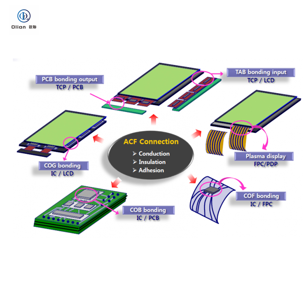
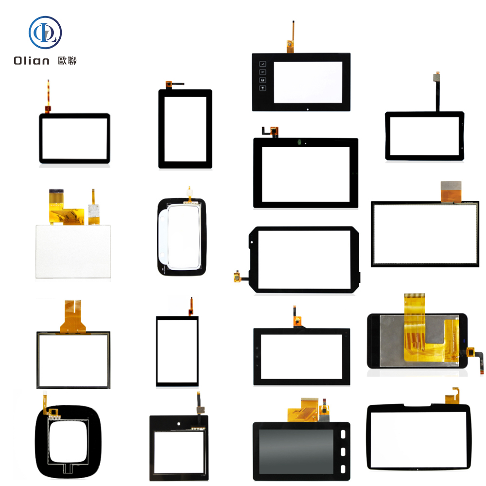
Anisotropic Conductive Films (ACF) have a wide range of applications in modern electronics, including the following key areas:
1. Electronics Packaging
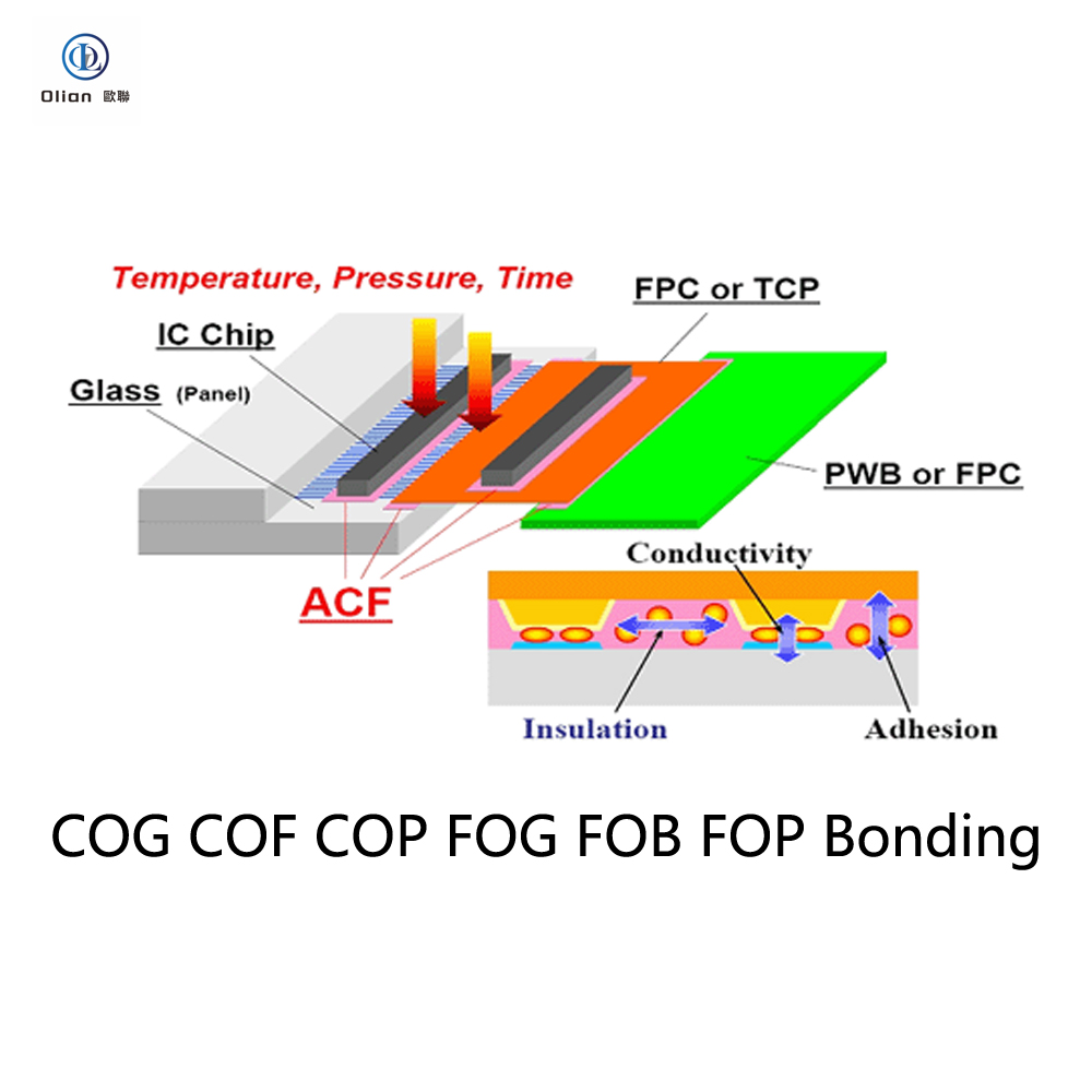
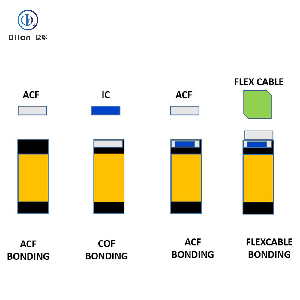
Chip-on-Glass (COG): ACF is used to bond driver ICs directly onto the glass substrate of liquid crystal displays (LCDs), enabling high-resolution and high-quality images.
Chip-on-Flex (COF): ACF facilitates the connection between chips and flexible circuits, allowing for compact and flexible designs in devices such as mobile phones and tablets.
Flip-Chip Bonding: ACF provides reliable electrical connections in flip-chip packaging, where the chip is mounted directly onto the substrate with the active side facing down.
2. Display Technology
LCDs and OLEDs: ACF is essential for bonding driver ICs to the display panels in both LCDs and organic light-emitting diode (OLED) displays, ensuring stable electrical connections and high image quality.
Micro LED Displays: ACF is used to bond micro LED chips to the display substrate, enabling high-brightness and high-efficiency displays.
3. Optoelectronic Devices
Light-Emitting Diodes (LEDs): ACF is used to bond LED chips to the substrate, providing efficient electrical connections and improving the overall performance of the LEDs.
Photovoltaic Cells: ACF can be used to bond photovoltaic cells to the substrate, enhancing the electrical conductivity and reliability of the solar panels.
4. Flexible Electronics and Wearable Devices
Flexible Printed Circuits (FPCs): ACF is used to bond FPCs to various substrates, such as glass or other flexible materials, enabling the development of flexible and foldable electronic devices.
Wearable Devices: ACF is used in wearable devices such as smartwatches, fitness trackers, and smart clothing, providing reliable and flexible connections .
5. Internet of Things (IoT) and Smart Devices
Sensors: ACF is used to bond sensors to glass or ceramic substrates, enabling high-precision and high-reliability sensor connections.
Smart Cards and RFID: ACF is used in smart cards and RFID tags.
providing secure and reliable electrical connections for data storage and transmission.
6. Automotive and Industrial Electronics
Automotive Electronics: ACF is used in automotive applications such as dashboard displays,
infotainment systems, and sensor connections, providing reliable and durable connections under harsh environmental conditions.
Industrial Equipment: ACF is used in industrial equipment for connections between electronic components and substrates,
ensuring high reliability and performance in demanding industrial environments.
7. Medical and Healthcare Devices
Medical Equipment: ACF is used in medical devices such as electrosurgical knives,
endoscopic imagers, and medical packaging, providing reliable and safe electrical connections.
Wearable Medical Devices: ACF is used in wearable medical devices such as health monitoring devices and wearable sensors, enabling comfortable and reliable connections.
These applications demonstrate the versatility and importance of ACF in modern electronics, enabling the development of compact,
high-performance, and reliable electronic devices across various industries.
In the rapidly evolving world of electronics and display manufacturing, precision bonding technologies play a crucial role in creating high-quality, reliable, and innovative products. Whether you are producing smartphone screens, wearable devices, large TV panels, or advanced OLED displays, our company offers a comprehensive range of bonding machines and solutions to meet your specific needs. Below is an introduction to our product offerings, covering various bonding technologies and applications.
Chip on Glass (COG) Bonding Machines
COG (Chip on Glass) technology is a widely used method for mounting LCD driver chips directly onto the glass substrate of a display panel
. This technique is known for its simplicity, cost-effectiveness, and reliability. Our COG bonding machines are designed to provide high precision and efficiency, making them ideal for applications such as smartphone screens, LCD panels, and other display devices
. We offer both pre-bonding and main-bonding machines, ensuring accurate alignment and strong connections.
Chip on Film (COF) Bonding Machines
COF (Chip on Film) technology represents a significant advancement in display manufacturing. It involves mounting integrated circuits (ICs) onto flexible printed circuits (FPCs), which can then be bent and folded to fit compact spaces
. Our COF bonding machines support high-speed production and offer precise temperature and pressure control, ensuring reliable connections for applications such as flexible screens, smartwatches, and other wearable devices
. We provide both COF pre-bonding and main-bonding machines, tailored to meet the demands of modern display manufacturing
.
Chip on Plastic (COP) Bonding Machines
COP (Chip on Plastic) technology is another innovative approach, where ICs are mounted directly onto plastic substrates. This method is particularly useful for creating lightweight and flexible displays
. Our COP bonding machines are designed to handle the unique challenges of plastic substrates, offering high precision and reliability. These machines are ideal for applications such as flexible OLED displays and wearable devices
.
FPC on Glass (FOG) Bonding Machines
FOG (FPC on Glass) bonding involves attaching flexible printed circuits to glass substrates. This technique is commonly used in applications requiring flexibility and compact design, such as touch screens and wearable devices
. Our FOG bonding machines feature advanced alignment systems and precise temperature control, ensuring high-quality connections. We offer both hot press and automated bonding solutions for FOG applications
.
FPC on PCB (FOB) Bonding Machines
FOB (FPC on PCB) bonding machines are designed for attaching flexible printed circuits to printed circuit boards. These machines are essential for creating compact and reliable electronic assemblies, commonly used in smartphones, tablets, and other consumer electronics
. Our FOB bonding machines provide high precision and flexibility, supporting both manual and automated production processes
.
FPC on FPC (FOF) Bonding Machines
FOF (FPC on FPC) bonding involves connecting flexible printed circuits to each other. This technique is ideal for applications requiring extreme flexibility and compactness, such as wearable devices and flexible displays
. Our FOF bonding machines offer high precision and reliability, ensuring strong and durable connections.
Anisotropic Conductive Film (ACF) Bonding Machines
ACF (Anisotropic Conductive Film) bonding is a versatile technique used in various bonding processes, including COG, COF, and FOG
. Our ACF bonding machines are designed to provide precise temperature, pressure, and alignment control, ensuring reliable and high-quality connections. We offer a range of ACF bonding solutions, including pre-bonding and main-bonding machines
.
Tape Automated Bonding (TAB) Machines
TAB (Tape Automated Bonding) is a technique used for bonding integrated circuits to substrates using tape carriers. Our TAB bonding machines are designed for high-speed production and offer precise alignment and bonding capabilities
. These machines are ideal for applications requiring high-density interconnections and compact designs
.
Flexible Printed Circuit (FPC) Bonding Machines
FPC (Flexible Printed Circuit) bonding machines are essential for creating flexible and lightweight electronic assemblies. Our FPC bonding machines offer high precision and reliability, supporting various bonding processes and applications
. These machines are ideal for applications such as wearable devices, flexible displays, and other consumer electronics
.
Additional Bonding Solutions
In addition to the above technologies, we also offer specialized bonding machines for various applications, including:
Touch Panel FPC Bonding Machines: For bonding flexible circuits to touch panels.
Zebra Paper Bonding Machines: For bonding components to Zebra paper.
Pulse Hot Press Machines: For applications requiring rapid heating and cooling.
OLED Bonding Machines: For bonding OLED displays.
Camera FPC Bonding Machines: For bonding flexible circuits to camera modules.
Why Choose Our Bonding Machines?
Our bonding machines are designed with the latest innovations in mind, ensuring high precision, reliability, and efficiency. Key features of our machines include:
High Precision: Equipped with advanced vision systems and precise temperature control.
Versatility: Support a wide range of bonding processes and applications.
Automation: Available in both semi-automatic and fully automatic configurations.
Customization: Tailored solutions to fit your specific manufacturing processes and requirements.
Conclusion
Whether you are producing smartphone screens, wearable devices, large TV panels, or advanced OLED displays, our comprehensive range of bonding machines is designed to meet your specific needs. With advanced features such as high precision, versatility, and automation, our machines are ideal for ensuring high-quality connections and efficient production processes. Contact us today to find the perfect bonding machine for your application.
Advanced Bonding Machines for Display and Electronics Manufacturing
In the dynamic world of electronics and display manufacturing, precision and reliability are paramount. Whether you are producing smartphone screens, wearable devices, large TV panels, or advanced OLED displays, the right bonding machine is essential for ensuring high-quality connections and efficient production processes. Our company offers a wide range of state-of-the-art bonding machines designed to meet the diverse needs of modern manufacturing. Below is an overview of our product offerings, tailored to help you find the perfect solution for your specific requirements.
Bonding Machines for Mobile and Wearable Devices
Mobile Phone Bonding Machines
Our mobile phone bonding machines are designed to handle the precise assembly requirements of smartphones. These machines support various bonding processes, including COG (Chip on Glass), COF (Chip on Film), and FPC (Flexible Printed Circuit) bonding. They are equipped with high-definition microscopes, digital pressure gauges, and vacuum generators to ensure accurate alignment and reliable bonding
Smart Watch LCD Bonding Machines
For the growing wearable technology market, our smart watch LCD bonding machines offer high precision and flexibility. These machines are ideal for bonding small LCD panels and flexible circuits, ensuring that your wearable devices are both durable and reliable
Wearable Equipment Bonding Machines
Our wearable equipment bonding machines are versatile and can handle a variety of components used in smartwatches, fitness trackers, and other wearable devices. These machines support multiple bonding processes, including COG, COF, and FOG (Film on Glass) bonding
Bonding Machines for Display Panels
TV Panel Bonding Machines
Our TV panel bonding machines are designed for large-scale production of LCD and LED TV panels. These machines support high-speed bonding processes and are equipped with advanced features such as pulse heating and constant temperature control to ensure consistent bonding quality
LCM and LCD Module Bonding Machines
For the production of Liquid Crystal Modules (LCMs) and LCD modules, our bonding machines offer high precision and reliability. These machines support various bonding processes, including COG, FOG, and OLB (Outer Lead Bonding), and are suitable for both small and large-scale production
Flat Panel Display Bonding Machines
Our flat panel display bonding machines are designed to handle a wide range of display sizes and types, from small wearable devices to large TV panels. These machines are equipped with advanced vision systems and precise temperature control to ensure high-quality bonding
Specialized Bonding Machines
COG, COP, and COF Bonding Machines
Our COG (Chip on Glass), COP (Chip on Plastic), and COF (Chip on Film) bonding machines are designed for high-precision bonding of integrated circuits (ICs) and flexible printed circuits (FPCs) to various substrates. These machines offer both semi-automatic and fully automatic configurations, making them suitable for a wide range of production volumes
FOG, FOB, and FOF Bonding Machines
Our FOG (Film on Glass), FOB (Film on Board), and FOF (Film on Film) bonding machines are designed for bonding flexible circuits to various substrates. These machines support both pulse heating and constant temperature bonding processes, ensuring reliable connections in your display assemblies
TAB, OLB, and IC Bonding Machines
Our TAB (Tape Automated Bonding), OLB (Outer Lead Bonding), and IC bonding machines are versatile tools for bonding integrated circuits and other components. These machines offer high precision and reliability, making them ideal for a wide range of electronic manufacturing applications
FPC, Glass, and Touch Panel Bonding Machines
Our FPC (Flexible Printed Circuit), glass, and touch panel bonding machines are designed to handle the specific requirements of flexible circuits and touch-sensitive displays. These machines support various bonding processes, including COG, FOG, and COF bonding, and are equipped with advanced features such as high-definition microscopes and precise temperature control
OLED, Mini LED, and Micro LED Bonding Machines
For advanced display technologies such as OLED, Mini LED, and Micro LED, our bonding machines offer high precision and reliability. These machines are designed to handle the specific requirements of these advanced displays, ensuring high-quality connections and efficient production
Zebra Paper and Flex Cable Bonding Machines
Our Zebra paper and flex cable bonding machines are designed for bonding components to Zebra paper and flexible cables. These machines offer high precision and reliability, making them ideal for applications where flexibility and compactness are crucial
Why Choose Our Bonding Machines?
Our bonding machines are designed with the latest innovations in mind, ensuring high precision, reliability, and efficiency. Key features of our machines include:
High Precision: Equipped with advanced vision systems and precise temperature control, our machines ensure reliable connections.
Versatility: Our machines support a wide range of bonding processes and can handle various substrates and components.
Automation: Available in both semi-automatic and fully automatic configurations, our machines can meet the needs of small-scale production and large-scale manufacturing.
Customization: We offer tailored solutions to fit your specific manufacturing processes and requirements.
Conclusion
Whether you are producing smartphone screens, wearable devices, large TV panels, or advanced OLED displays, our comprehensive range of bonding machines is designed to meet your specific needs. With advanced features such as high precision, versatility, and automation, our machines are ideal for ensuring high-quality connections and efficient production processes. Contact us today to find the perfect bonding machine for your application.
In the modern electronics manufacturing landscape, Anisotropic Conductive Film (ACF) bonding machines have become indispensable tools for creating reliable and high-quality connections between various components. Whether you are involved in the production of LCD panels, flexible circuits, or advanced display technologies, the right ACF bonding machine can significantly enhance your manufacturing efficiency and product quality. This article provides an in-depth introduction to the different types of ACF bonding machines and their applications, helping you find the perfect solution for your needs.
ACF Bonding Parts and AccessoriesSmart Wear LCD OLED Bonding Production Whole Line SolutionFOG FOP FOF FOB T-FOG FPC Flex Cable Bonding MachineFOG FOP FOF FOB T-FOG FPC Flex Cable Bonding MachineFOG FOP FOF FOB T-FOG FPC Flex Cable Bonding MachineFPC PRE BONDING MAIN BONDERIC MIAN BONDERCOF PRE BONDER MAIN BONDERCOF COP COG IC PRE BONDERCOF COP COG IC BONDERFOG FOP FOF FOB T-FOG FPC Flex Cable Bonding MachineFOG FOP FOF FOB T-FOG FPC Flex Cable Bonding Machine7-17INCH FOG FOB PRE AND MAIN BONDING MACHINE
Introduction to ACF Bonding Machines
ACF bonding machines are specialized devices designed to bond two substrates using Anisotropic Conductive Film (ACF). These machines apply heat, pressure, and precise alignment to ensure a strong and reliable electrical and mechanical connection between components such as LCD panels, PCBs, FPCs, and IC chips
. ACF bonding is widely used in applications like COG (Chip on Glass), COF (Chip on Film), FOG (Film on Glass), FOB (Film on Board), and more
.
Types of ACF Bonding Machines
1. ACF Pre-Bonding Machines
ACF pre-bonding machines are used for the initial alignment and attachment of ACF tape to the substrates. These machines often feature semi-automatic operation, allowing operators to place the components manually while the machine handles precise alignment and pre-bonding
. Pre-bonding ensures that the components are accurately positioned before the final bonding process.
2. ACF Main-Bonding Machines
Main-bonding machines are responsible for the final bonding process, where the components are pressed together under precise temperature and pressure conditions. These machines are available in both constant heat and pulse heat systems, offering flexibility based on the specific requirements of the bonding process
. Main-bonding machines can be fully automated, providing high throughput and consistent bonding quality.
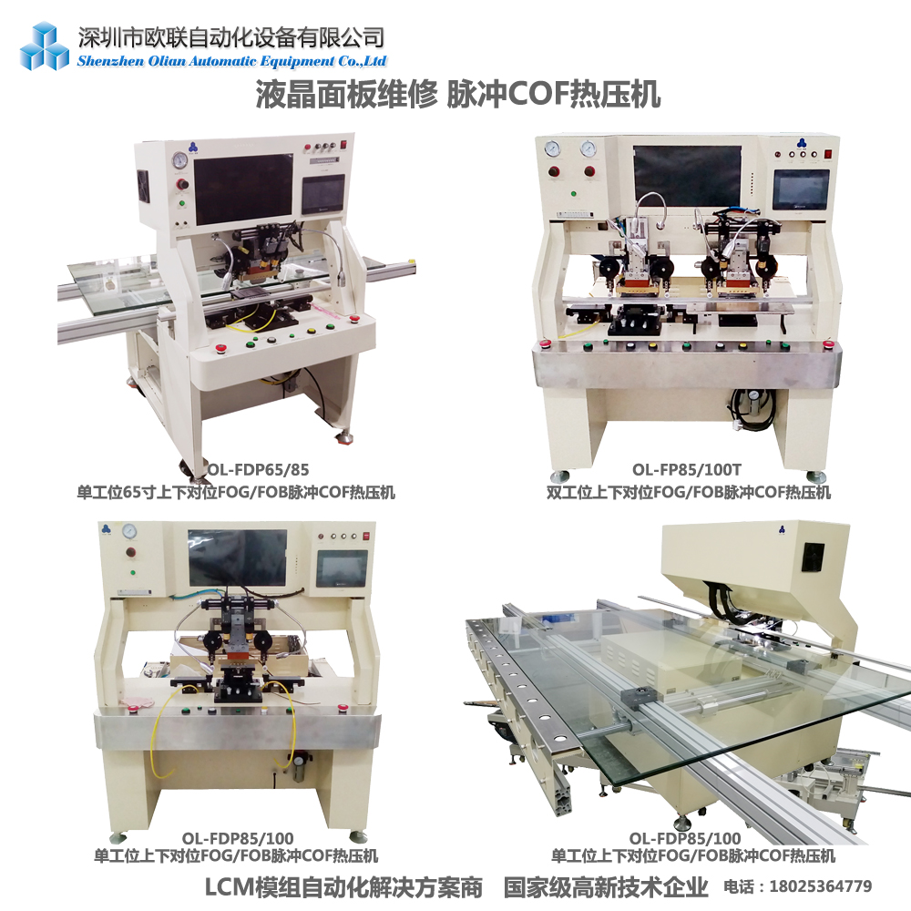
3. ACF Heat Press Machines
ACF heat press machines, also known as hot press machines, are versatile tools used for bonding components using ACF. These machines can operate in both constant temperature and pulse heating modes, making them suitable for a wide range of applications
. They are equipped with features like multi-stage temperature control, real-time temperature curve display, and CCD vision systems for precise alignment
.
4. Pulse Heating Bonding Machines
Pulse heating bonding machines use a transformer to generate low voltage and high current, which quickly heats the bonding area. This method allows for rapid heating and cooling, ensuring precise temperature control and efficient bonding
. Pulse heating machines are ideal for applications where quick and precise bonding is required, such as in COF and FOG bonding processes
.
5. Constant Temperature Bonding Machines
Constant temperature bonding machines maintain a steady temperature throughout the bonding process. These machines are widely used in LCD panel assembly and other applications where consistent temperature control is crucial
. They offer features like digital pressure gauges, vacuum generators, and high-definition microscopes for precise bonding
.
Applications of ACF Bonding Machines
ACF bonding machines are used in various industries, including:
LCD and LED Panel Manufacturing: For bonding ICs, FPCs, and other components to glass substrates.
Flexible Circuit Assembly: For creating connections between flexible printed circuits and other components.
Touch Screen Production: For bonding touch sensors to display panels.
Mobile Phone and Tablet Manufacturing: For assembling components in mobile devices.
Why Choose Our ACF Bonding Machines?
Our company offers a comprehensive range of ACF bonding machines designed to meet the diverse needs of the electronics manufacturing industry. Our machines are known for their:
High Precision: Equipped with advanced vision systems and precise temperature control.
Versatility: Available in both semi-automatic and fully automatic configurations.
Reliability: Built with high-quality components and rigorous testing.
Customization: Tailored solutions to fit specific manufacturing processes.
Conclusion
ACF bonding machines are essential tools in modern electronics manufacturing, providing reliable and high-quality connections between various components. Whether you need a pre-bonding machine for initial alignment or a main-bonding machine for the final assembly, our company offers a wide range of solutions to meet your needs. With advanced features like pulse heating, constant temperature control, and precise alignment, our ACF bonding machines are designed to enhance your manufacturing efficiency and product quality. Contact us today to find the perfect ACF bonding machine for your application.
In the rapidly evolving world of display technology, bonding machines play a crucial role in the assembly and manufacturing of various electronic components and displays. Our company is proud to offer a wide range of advanced bonding solutions tailored to meet the diverse needs of the industry. Whether you are looking to bond integrated circuits, flexible printed circuits, or other components, we have the right machine for you.
Mid Size 7-17 Inch Vehicle Display and Notebook Whole Line SolutionACF Bonding Parts and AccessoriesMobile Phones Tablets and Industrial Control Products Whole Line Solution for TFT DisplaysFOG FOP FOF FOB T-FOG FPC Flex Cable Bonding MachineFOG FOP FOF FOB T-FOG FPC Flex Cable Bonding MachineFOG FOP FOF FOB T-FOG FPC Flex Cable Bonding MachineIC MIAN BONDERCOF COP COG IC PRE BONDERCOF IC BONDER7-17 Inch Semi Automatic Bonding Machines Production Line SolutionFOG FOP FOF FOB T-FOG FPC Flex Cable Bonding MachineFOG FOP FOF FOB T-FOG FPC Flex Cable Bonding Machine
ACF Bonder (Anisotropic Conductive Film Bonder)
ACF bonders are essential for bonding two substrates, such as LCDs, PCBs, and FPCs, using Anisotropic Conductive Film (ACF). These machines are available in both constant heat and pulse heat systems, with vision alignment capabilities for precise bonding
. They are widely used in applications like COB (Chip on Board), COF (Chip on Film), COG (Chip on Glass), COP (Chip on Panel), FOB (Film on Board), and FOG (Film on Glass).
COG Bonder (Chip on Glass Bonder)
COG bonders are specifically designed for attaching integrated circuits (ICs) directly onto glass substrates. These machines ensure high precision and reliability, making them ideal for the production of LCD panels used in consumer electronics, automotive displays, and industrial applications
. Our COG bonders come in both pre-bonding and main-bonding configurations, with options for manual or automated loading.
COP Bonder (Chip on Panel Bonder)
Similar to COG bonders, COP bonders are used for bonding ICs directly onto display panels. They are particularly useful for flexible AMOLED production, offering advanced functions to ensure high bonding quality and productivity
.
COF Bonder (Chip on Film Bonder)
COF bonders are designed for bonding ICs onto flexible films. These machines are versatile and can be used for various applications, including COF on glass, COF on board, and COF on film bonding
. They are available in both manual and automatic configurations, with options for single or dual heads.
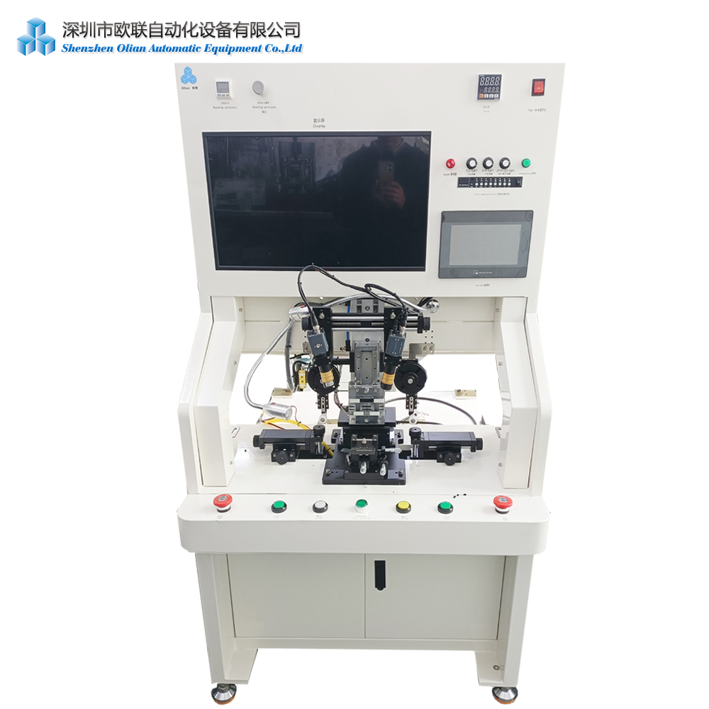
FOG Bonder (Film on Glass Bonder)
FOG bonders are used for bonding flexible printed circuits (FPCs) onto glass substrates. These machines come in both pulse heat and constant heat versions, with top-bottom alignment systems for precise bonding
. They are suitable for a wide range of applications, including LCD and OLED panel manufacturing.
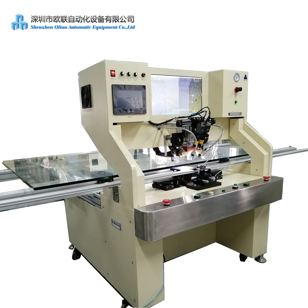
FOB Bonder (Film on Board Bonder)
FOB bonders are designed for bonding FPCs onto PCBs. They offer similar features to FOG bonders, including precise alignment and reliable bonding capabilities
. These machines are essential for applications where flexibility and compactness are required.
FOF Bonder (Film on Film Bonder)
FOF bonders are used for bonding FPCs onto other FPCs. These machines are particularly useful in applications where space is limited and flexibility is crucial
. They offer high precision and reliability, ensuring a strong and stable connection between the components.
TAB Bonder (Tape Automated Bonding Machine)
TAB bonders are used for bonding integrated circuits onto substrates using tape automated bonding techniques. These machines are known for their high precision and reliability, making them ideal for a wide range of electronic manufacturing applications
.
OLB Bonder (Outer Lead Bonding Machine)
OLB bonders are used for bonding the outer leads of integrated circuits onto substrates. These machines are essential for ensuring a reliable connection between the IC and the display panel
. They offer high precision and reliability, making them a crucial part of the display manufacturing process.
IC Bonder (Integrated Circuit Bonder)
IC bonders are versatile machines used for bonding integrated circuits onto various substrates. They are available in both manual and automated configurations, with options for single or dual heads
. These machines are essential for a wide range of electronic manufacturing applications.
FPC Bonder (Flexible Printed Circuit Bonder)
FPC bonders are designed for bonding flexible printed circuits onto various substrates. These machines offer high precision and reliability, making them ideal for applications where flexibility and compactness are required
. They are available in both manual and automated configurations, with options for single or dual heads.
Glass Bonder
Glass bonders are used for bonding components directly onto glass substrates. These machines are essential for the production of LCD and OLED panels, offering high precision and reliability
. They are available in both manual and automated configurations, with options for single or dual heads.
LCD Panel Bonder
LCD panel bonders are specifically designed for the assembly of LCD panels. These machines offer high precision and reliability, ensuring a strong and stable connection between the components
. They are available in both manual and automated configurations, with options for single or dual heads.
LED Panel Bonder
LED panel bonders are used for bonding components onto LED panels. These machines offer high precision and reliability, making them ideal for applications where brightness and efficiency are crucial
. They are available in both manual and automated configurations, with options for single or dual heads.
Mini LED Bonder
Mini LED bonders are designed for the assembly of Mini LED panels. These machines offer high precision and reliability, ensuring a strong and stable connection between the components
. They are available in both manual and automated configurations, with options for single or dual heads.
Micro LED Bonder
Micro LED bonders are used for the assembly of Micro LED panels. These machines offer extremely high precision and reliability, making them ideal for applications where brightness, efficiency, and resolution are crucial
. They are available in both manual and automated configurations, with options for single or dual heads.
Zebra Paper Bonder
Zebra paper bonders are used for bonding components onto Zebra paper. These machines offer high precision and reliability, making them ideal for applications where flexibility and compactness are required
. They are available in both manual and automated configurations, with options for single or dual heads.
Touch Panel FPC Bonder
Touch panel FPC bonders are specifically designed for bonding flexible printed circuits onto touch panels. These machines offer high precision and reliability, ensuring a strong and stable connection between the components
. They are available in both manual and automated configurations, with options for single or dual heads.
Conclusion
Our company offers a comprehensive range of bonding machines designed to meet the diverse needs of the display manufacturing industry. From ACF bonders to Micro LED bonders, we have the right machine for every application. Our machines are known for their high precision, reliability, and versatility, making them ideal for a wide range of electronic manufacturing applications. We are committed to providing our customers with the best possible solutions and support to ensure their success in the competitive world of display technology.
In the modern electronics repair industry, having the right tools and machines is crucial for efficiently repairing and refurbishing LCD and LED screens, especially for TVs and other large displays. Our company offers a wide range of advanced repair machines and bonding equipment designed to meet the diverse needs of professionals in this field. Whether you are repairing LCD TVs, smartphones, or other display devices, our products are designed to provide high precision, reliability, and efficiency.
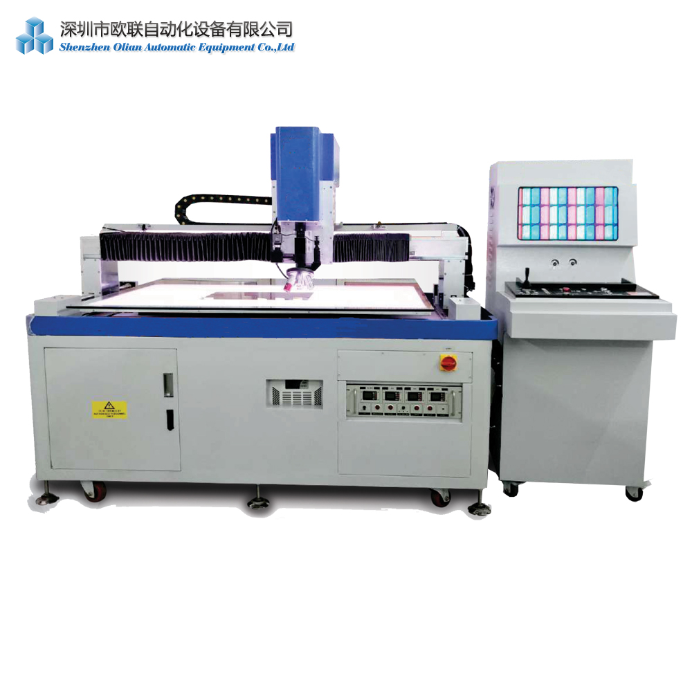
LCD Screen Laser Repair Machines
Our LCD screen laser repair machines are designed to efficiently repair a variety of defects in LCD panels, including vertical lines, horizontal lines, black screens, and more. These machines use high-frequency pulse laser beams to cut and trim micron-sized semiconductor circuit components, especially passivation layers (silicon oxide/nitride) and metal interconnects
They are suitable for repairing LCD screens in TVs, PCs, touch teaching machines, splicing screens, notebooks, digital devices, and car displays
Key Features:
High-Precision Laser Technology: Capable of repairing defects at the micron level.
Multi-Wavelength Options: Available in 1064nm and 532nm wavelengths for different repair needs.
Digital Spot System: Allows for precise control over repair processes.
Wide Application Range: Suitable for screens up to 85 inches.
COF Bonding Machines
Our COF (Chip-On-Film) bonding machines are essential for repairing and assembling LCD and LED panels. These machines are used to bond integrated circuits (ICs) to flexible film substrates, enabling compact designs and high-resolution displays
They are widely used in the repair and manufacturing of TVs, laptops, mobile phones, and tablets
Thermocompression Bonding: Uses heat and pressure to create reliable electrical connections.
Quality Inspection: In-line inspection systems verify bond quality.
Versatility: Suitable for various display sizes and types.
FOB and FOG Bonding Machines
Our FOB (FPC on Board) and FOG (FPC on Glass) bonding machines are designed for bonding flexible printed circuits (FPCs) to PCBs and glass substrates. These machines offer high precision and reliability, making them ideal for applications requiring flexible and compact designs
Key Features:
Pulse Heating Technology: Ensures precise temperature control.
High-Speed Automation: Increases production efficiency.
Versatile Compatibility: Supports various display sizes and types.
Hot Bar Pressing Machines
Our hot bar pressing machines are designed for soldering FPCs, PCBs, LED displays, and other electronic components. These machines use pulse heating technology to achieve accurate temperature control, making them suitable for temperature-critical applications
Key Features:
Multi-Zone Temperature Control: Ensures precise heating and cooling.
High-Precision Indenter: Made from high-quality materials for durability.
User-Friendly Interface: Equipped with a touch screen for easy operation.
LCD Panel Rework and Repair Equipment
Our LCD panel rework and repair equipment includes a variety of machines designed to refurbish and repair LCD panels. These machines are capable of repairing a wide range of defects, including vertical and horizontal lines, black screens, and more
Key Features:
HD Screen Display: Provides clear and detailed images for precise repair.
One-Touch Start: Simplifies the repair process with automated functions.
Upgraded Components: Includes high-precision regulators and camera brackets for accurate alignment.
Additional Tools and Equipment
COF Cutting Equipment: Designed for precise cutting of COF components.
Panel Repairing Machines: Suitable for repairing various display panels, including those in TVs and other devices.
ACF Attaching Machines: Used for attaching Anisotropic Conductive Film (ACF) to various substrates.
Why Choose Our Products?
Our products are designed with the latest innovations in mind, ensuring high precision, reliability, and efficiency. Key reasons to choose our products include:
High Precision: Equipped with advanced vision systems and precise temperature control.
Versatility: Suitable for a wide range of bonding processes and applications.
Automation: Available in both semi-automatic and fully automatic configurations.
Customization: Tailored solutions to fit your specific manufacturing processes and requirements.
Conclusion
Whether you are repairing LCD TVs, smartphones, or other display devices, our comprehensive range of repair machines and bonding equipment is designed to meet your specific needs. With advanced features such as high precision, versatility, and automation, our machines are ideal for ensuring high-quality repairs and efficient production processes. Contact us today to find the perfect solution for your application.
In the electronics manufacturing industry, particularly in the ACF (Anisotropic Conductive Film) bonding process, a variety of testing machines and equipment are essential to ensure the quality and reliability of the final products. These machines play a crucial role in the production line, from initial material inspection to final product testing. Here is a comprehensive overview of the testing instruments and equipment used in ACF bonding processes:
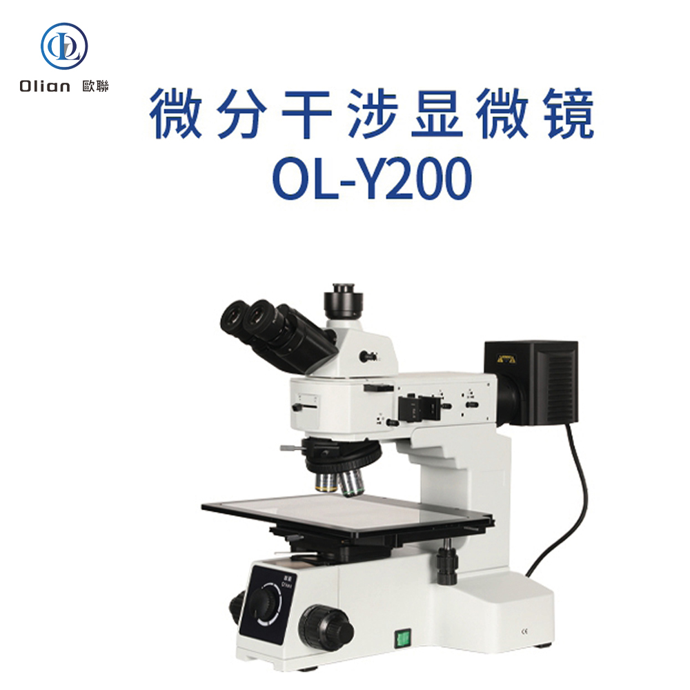
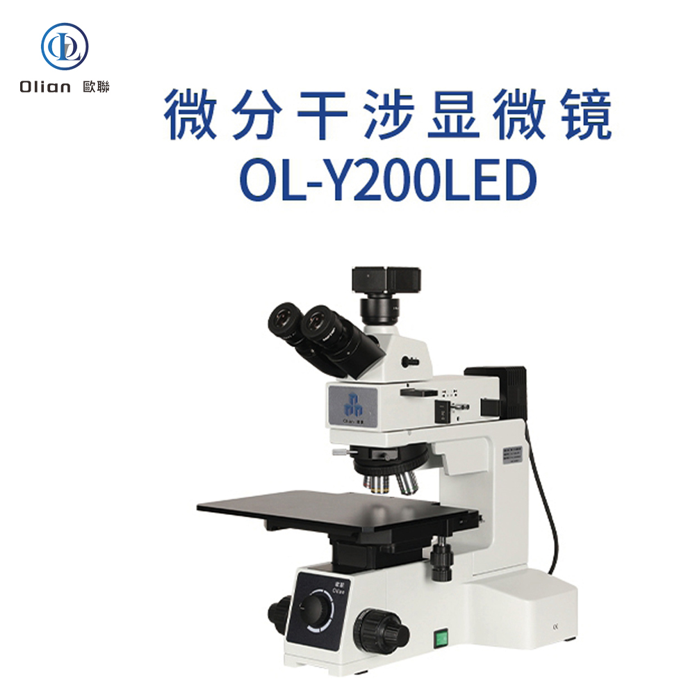
Interferometer Microscope: Interferometer microscopes are used to analyze the surface topography of materials with high precision. They are essential for inspecting the quality of ACF and the bonding surfaces of components. By using optical interference, these microscopes can detect minute surface irregularities that might affect the bonding process.
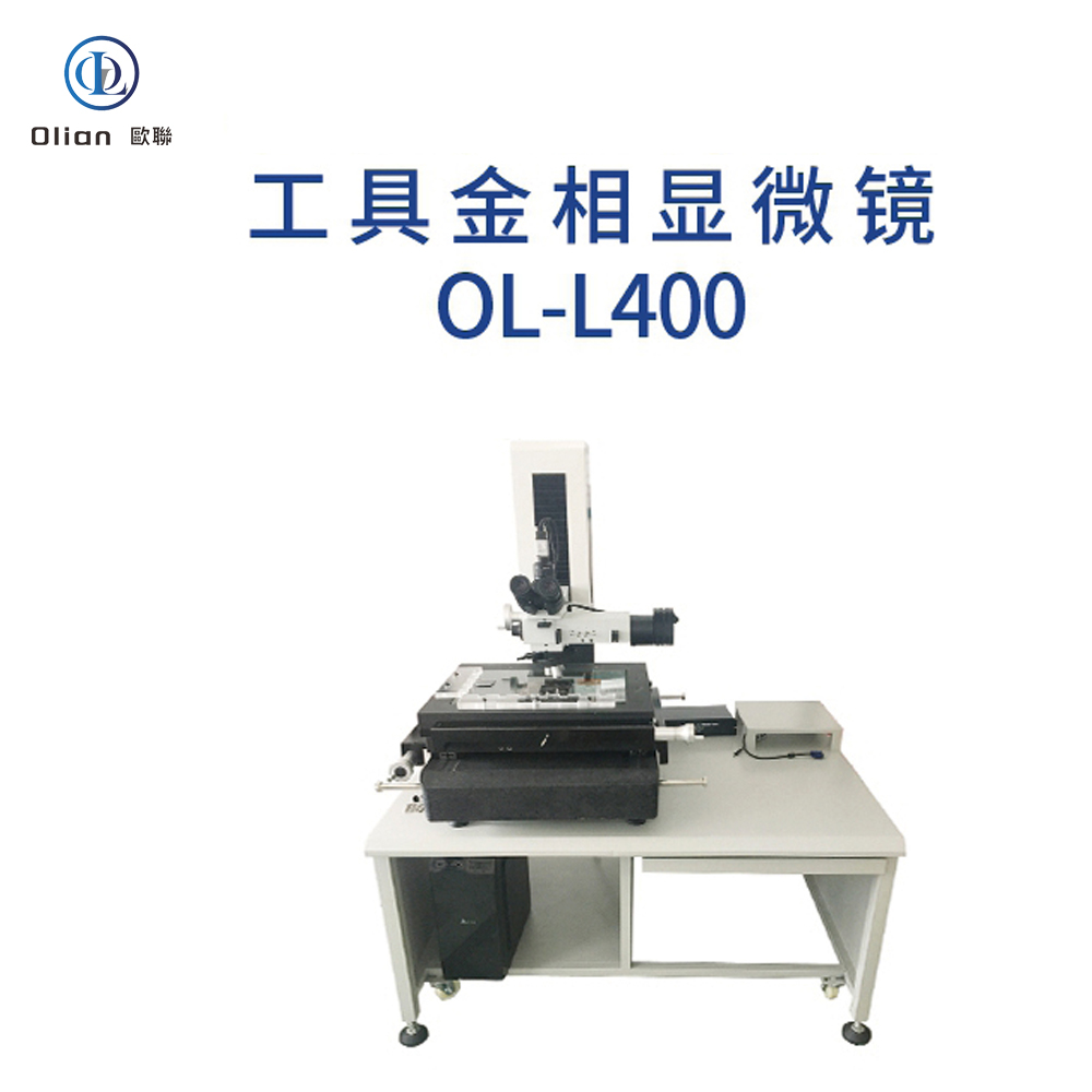
Metallographic Microscope: Metallographic microscopes are designed to examine the microstructure of metals and alloys. In the context of ACF bonding, they are used to analyze the metallurgical properties of the bonding sites. This helps in understanding the compatibility of the materials and the effectiveness of the bonding process.
Lens Inspection Microscope: Lens inspection microscopes are used to inspect and analyze optical components, such as the lenses used in display devices. They ensure that the optical properties of the components are maintained after the bonding process. High-resolution imaging helps in detecting any defects that might have occurred during bonding.
Tool Microscope: Tool microscopes are used for measuring and inspecting the dimensions and geometry of tools and mechanical parts. In ACF bonding, they are used to verify the alignment and precision of the bonding equipment. This ensures that the bonding process is accurate and consistent.
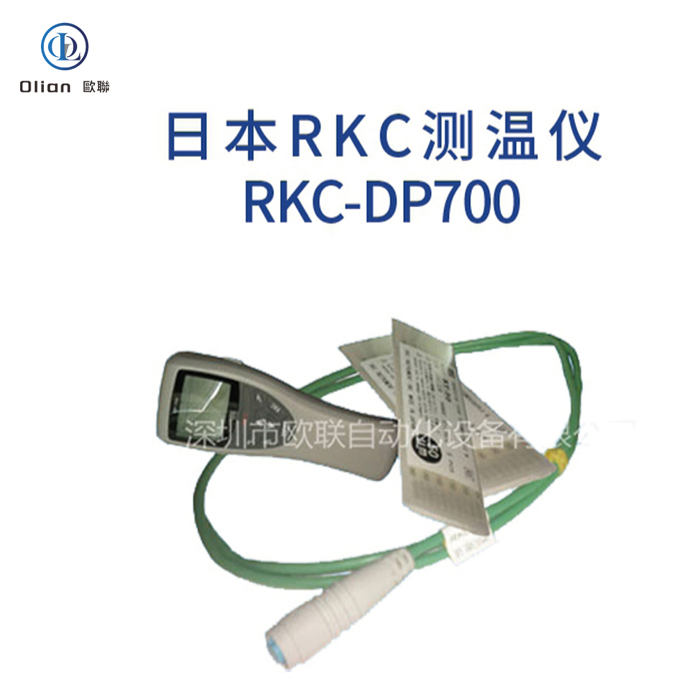
Temperature Testing Equipment
Temperature Testing Instrument: Temperature testing instruments are crucial for monitoring and controlling the temperature during the ACF bonding process. They ensure that the bonding temperature is maintained within the specified range, which is critical for the quality of the bond. These instruments can be contact or non-contact types, providing real-time temperature data.
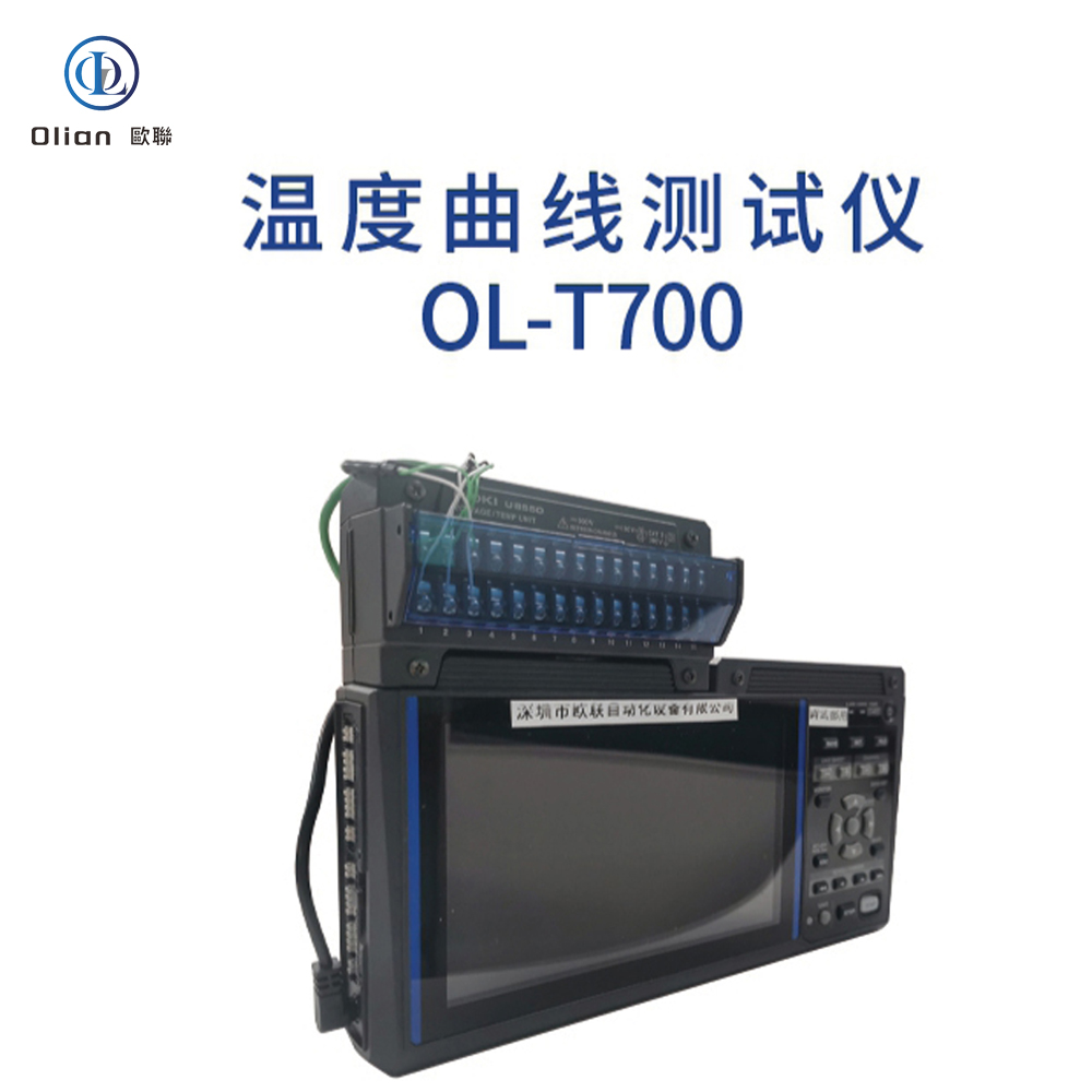
Temperature Curve Testing Instrument: Temperature curve testing instruments measure and record temperature changes over time. They are used to analyze the thermal behavior of the bonding process and to optimize the temperature profile. This helps in achieving a consistent and reliable bond quality.
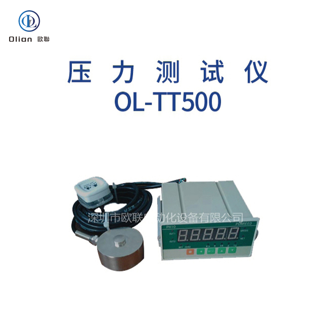
Pressure Testing Equipment
Pressure Testing Device: Pressure testing devices are used to measure and control the pressure applied during the ACF bonding process. They ensure that the pressure is uniform and within the specified limits, which is essential for a strong and durable bond. These devices can handle a wide range of pressures and provide precise control.
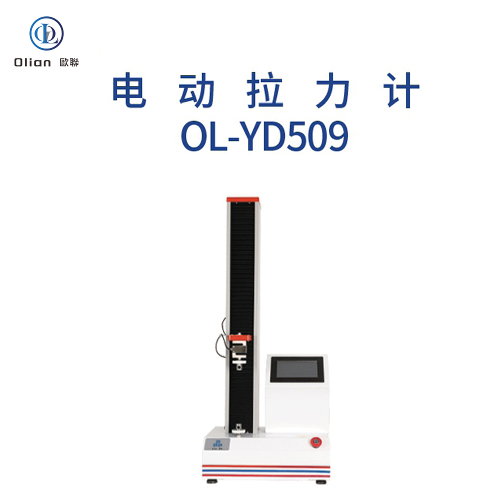
Tensile Testing Equipment
Tensile Testing Machine: Tensile testing machines are used to measure the tensile strength of the bonds created by the ACF process. They apply tensile force to the bonded components and measure the response. This helps in determining the mechanical strength of the bonds and ensuring that they can withstand the required forces.
Environmental Testing Chambers
High Temperature High Humidity Testing Chamber: These chambers simulate high temperature and high humidity conditions to test the adaptability and reliability of the bonded products. They are used to evaluate the long-term performance of the products under extreme environmental conditions.
Cold Hot Shock Testing Chamber: Cold hot shock testing chambers rapidly change the temperature to simulate extreme temperature variations. They are used to test the thermal shock resistance of the bonded products, ensuring that they can withstand rapid temperature changes without failure.
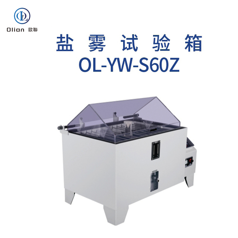
Salt Spray Testing Chamber: Salt spray testing chambers simulate a corrosive environment to test the corrosion resistance of the bonded products. This is particularly important for products that will be used in harsh environments, such as automotive and marine applications.
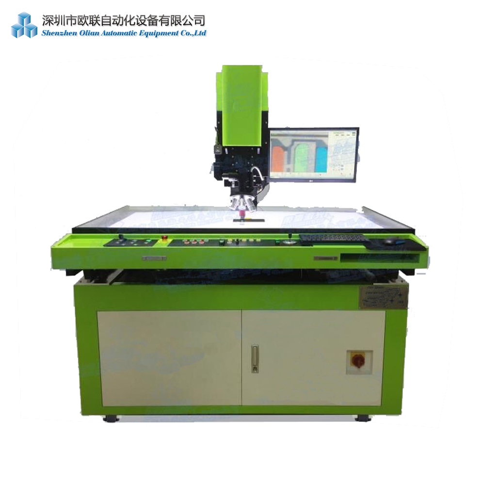
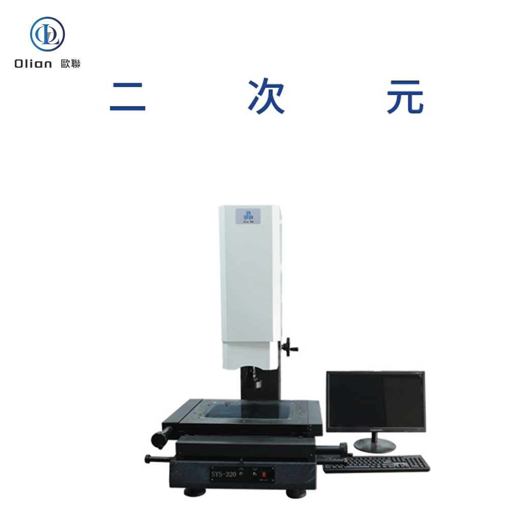
Dimensional and Surface Testing Equipment
2D Measuring Instrument: 2D measuring instruments use optical imaging and image processing to measure two-dimensional dimensions with high precision. They are used to verify the dimensional accuracy of the components before and after the bonding process. This ensures that the components meet the required specifications.
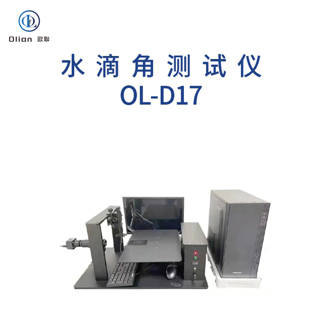
Contact Angle Meter: Contact angle meters measure the contact angle of a liquid on a solid surface, providing information about surface wettability and adhesion. In ACF bonding, they are used to evaluate the surface properties of the bonding sites, ensuring that the ACF can adhere properly.
Mechanical Testing Equipment
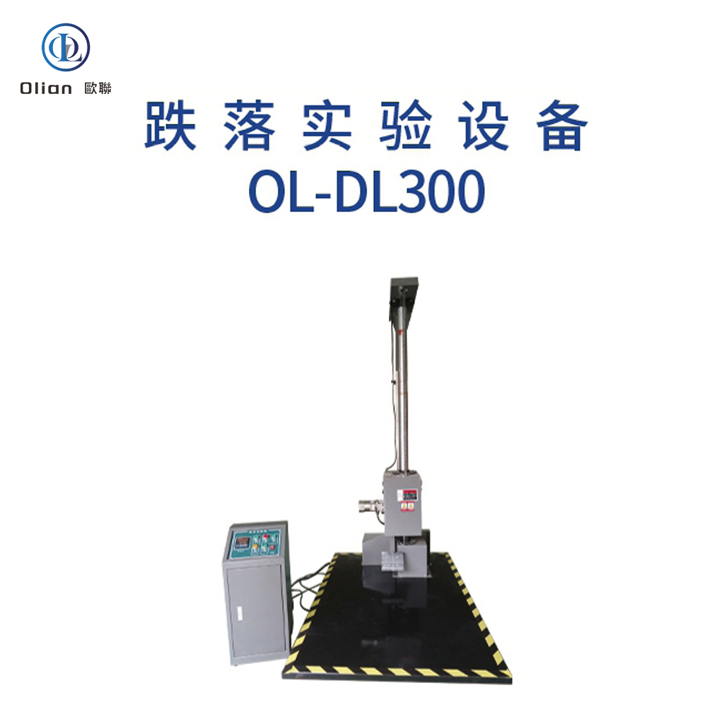
Drop Tester: Drop testers simulate the impact of dropping products to test their durability and shock resistance. They are used to ensure that the bonded products can withstand accidental drops during handling and transportation.
Vibration Testing Machine: Vibration testing machines simulate various vibration conditions to test the vibration resistance and reliability of the bonded products. They are used to ensure that the products can operate reliably in vibrating environments, such as in automotive and aerospace applications.
IC Disassembly and Removal Equipment
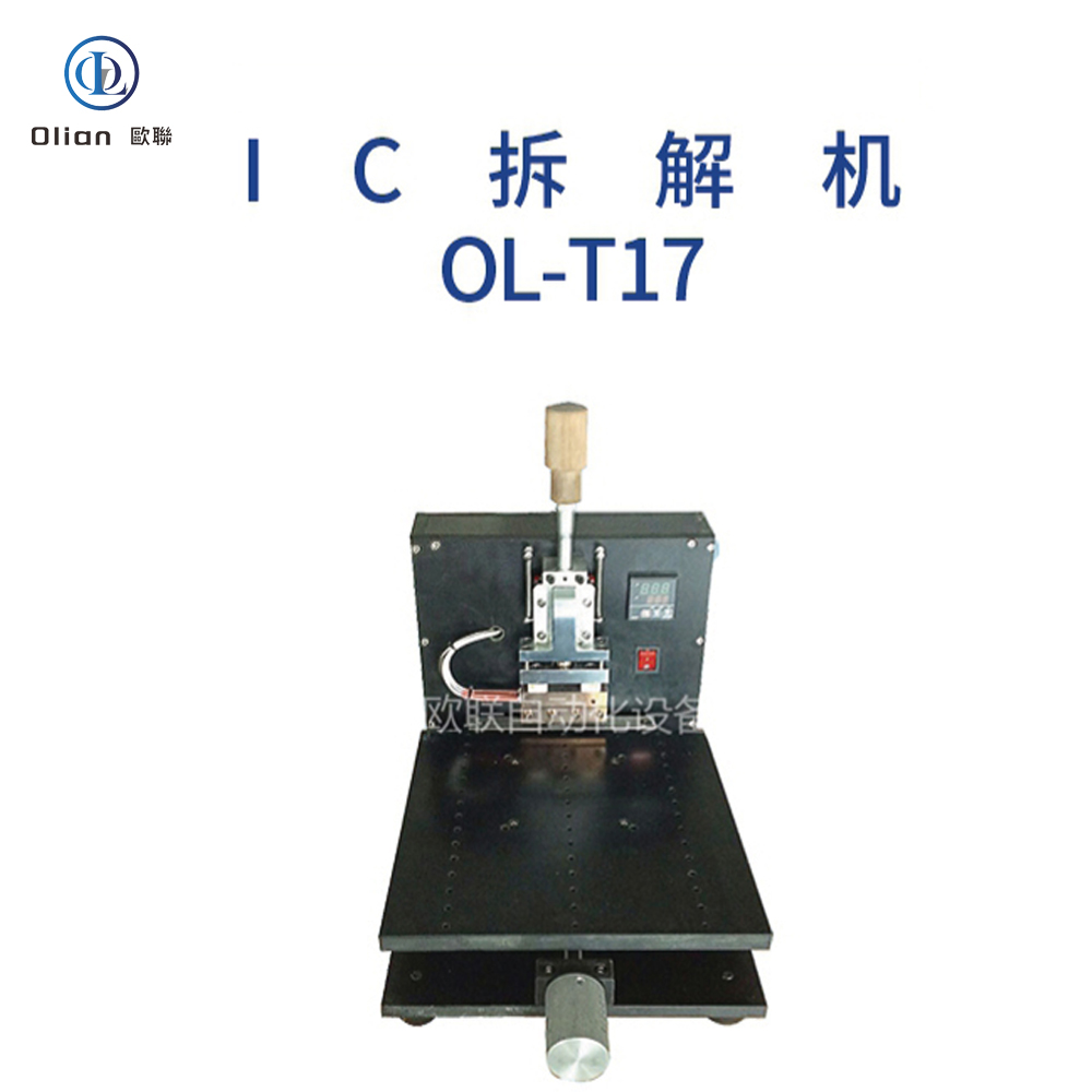
IC Disassembly Machine: IC disassembly machines are used to carefully remove integrated circuits (ICs) from their substrates without causing damage. This is crucial for repair and rework processes in the electronics industry.
IC Removal Machine: IC removal machines are designed to safely and efficiently remove ICs from printed circuit boards (PCBs). They are essential for maintaining the integrity of the board and the components during the repair process.
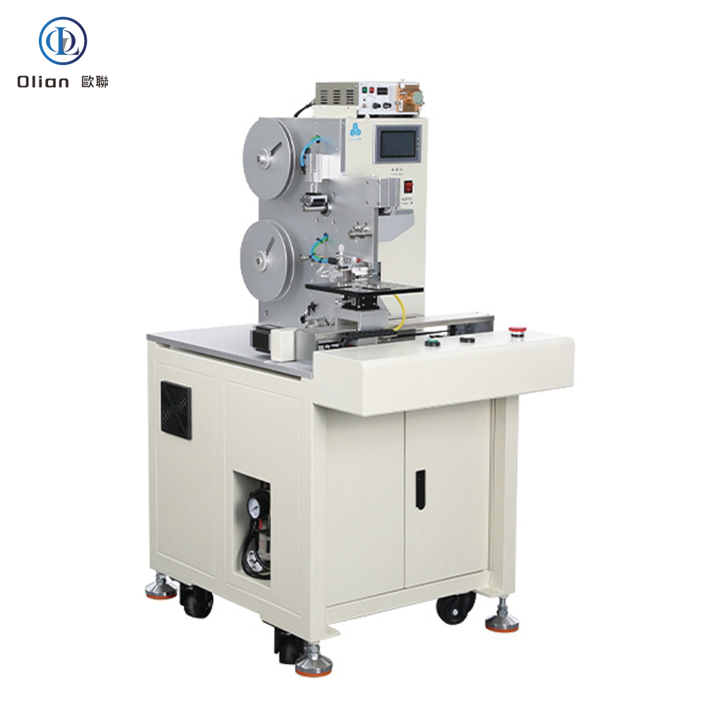
ACF Cutting and Bonding Equipment
ACF Cutting Machine: ACF cutting machines are used to cut the ACF tape to the required length and shape. These machines ensure that the ACF tape is accurately cut and positioned for the bonding process.
ACF Bonding Machine: ACF bonding machines are used to bond the ACF tape to the substrates (LCD, PCB, Flex, COF, IC Chip, FPC, etc.) using appropriate temperature, pressure, and time. These machines are available in various configurations, including constant heat systems and pulse heat systems, to meet different bonding requirements.
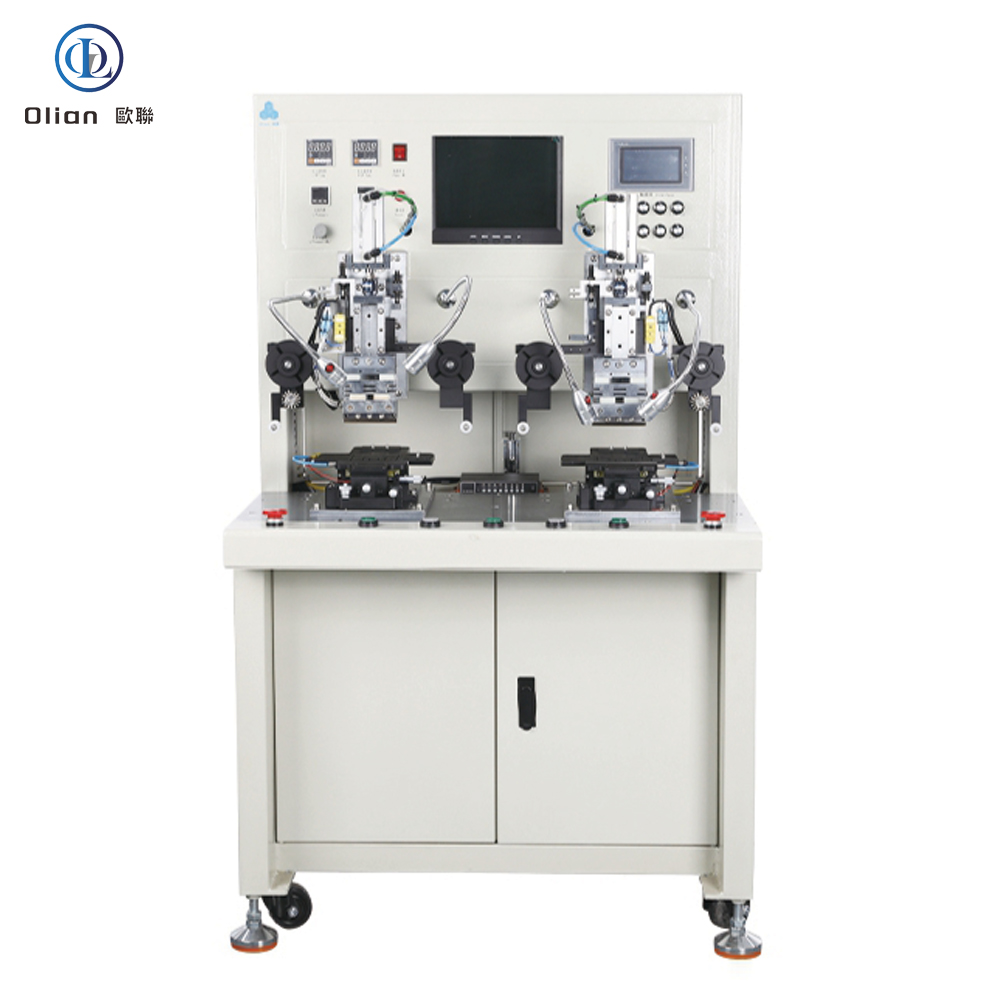
ACF Pre-Bonding Machine: ACF pre-bonding machines are used to pre-bond ICs or COF on the panel that has been attached to the ACF. The pick and place of the panel is achieved manually, and the pre-alignment is automatically completed by the equipment.
ACF Final Bonding Machine: ACF final bonding machines perform the main bonding on the LCD glass with IC, cable, or COF pre-pressed. The operator manually loads and unloads the products, while the ACF bonding is automatically performed by the machine.
Top-Bottom Alignment Bonding Machine: Top-bottom alignment bonding machines are used to bond FPC/Zebra paper on the PCB/Glass with the ACF attached. The pick and place and alignment of the PCB/Panel are done manually, and the ACF bonding is done automatically. These machines are suitable for 1″ to 12″ flat glass and flexible screen products bonding.
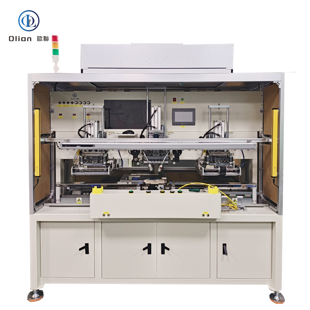
Fully Automatic ACF Bonding Line
A fully automatic ACF bonding line includes multiple machines working together to automate the entire bonding process. This includes substrates loading machines, terminal cleaning machines, fully automatic COG/COF/COP bonding machines, and fully automatic COF punching machines.
In conclusion, the ACF bonding process relies on a suite of sophisticated testing machines and equipment to ensure the quality and reliability of the final products. Each type of testing equipment plays a critical role in different stages of the production process, from initial material inspection to final product testing. By using these machines, manufacturers can optimize their processes, reduce defects, and ensure that their products meet the highest standards of quality and performance.
In the ACF (Anisotropic Conductive Film) bonding process, a variety of parts and accessories are used to ensure the quality and reliability of the final products. These components play a crucial role in the production line, from initial material preparation to final product testing. Here is a comprehensive overview of the parts and accessories used in ACF bonding processes:
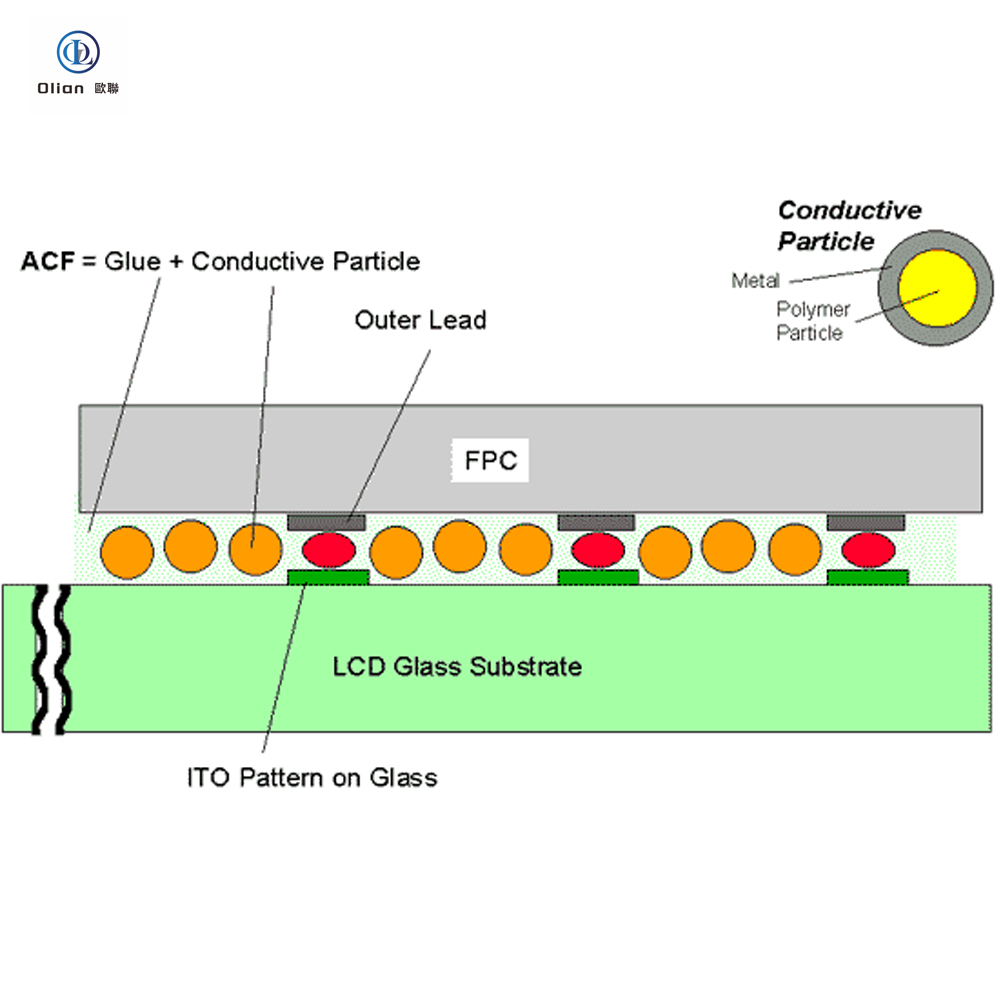
ACF Tape
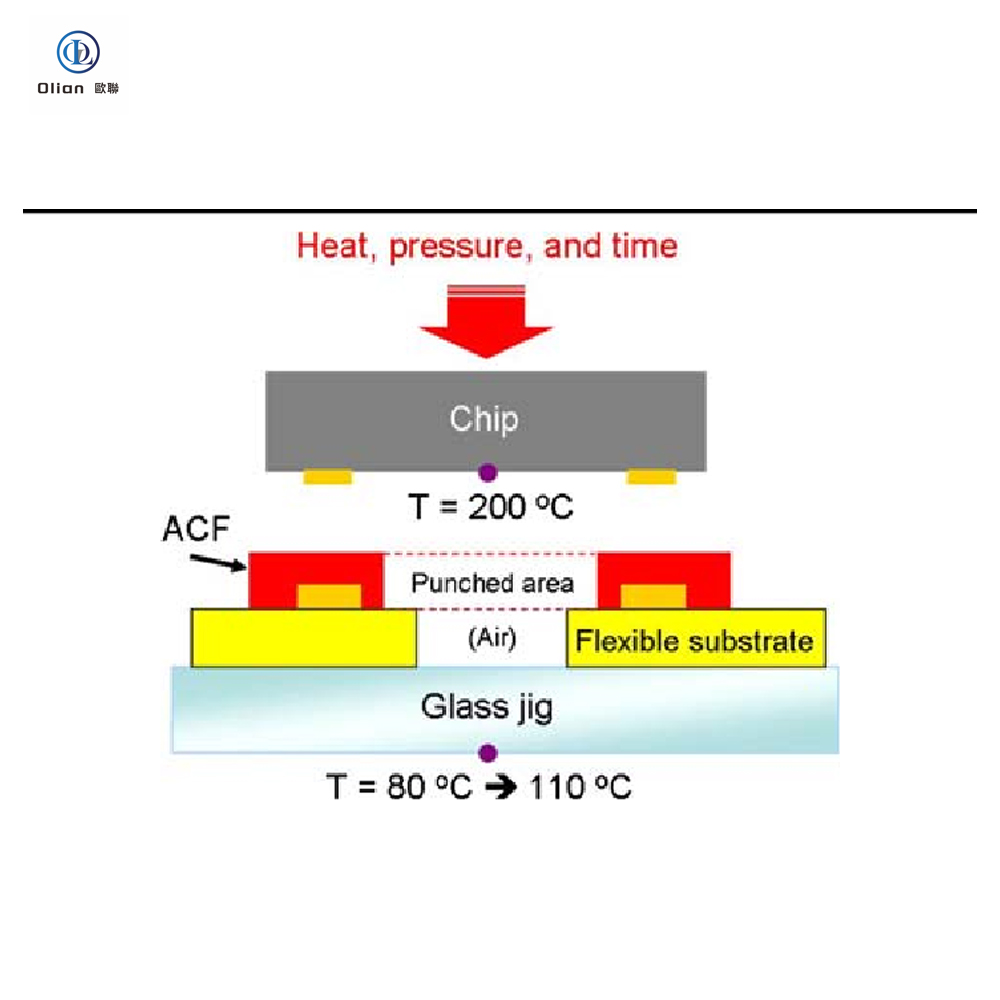
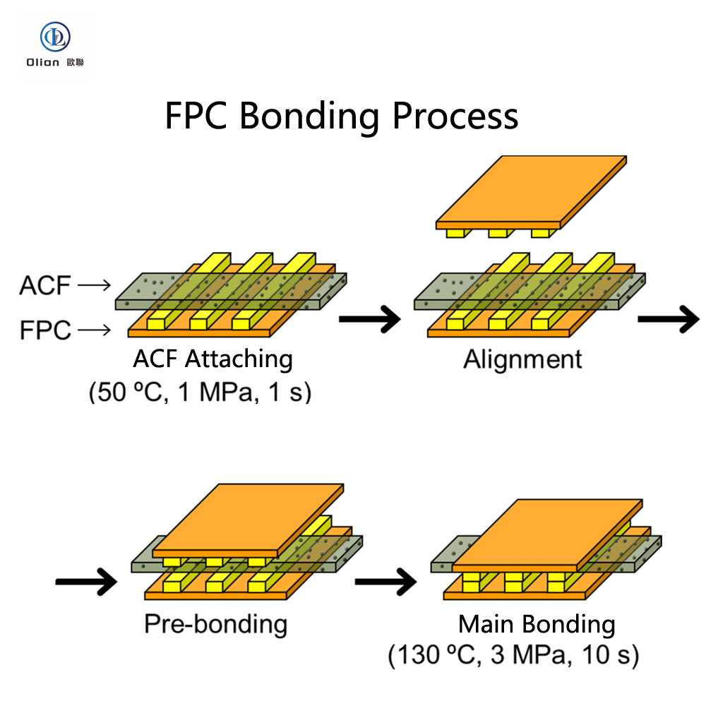
ACF Tape is the core material used in the ACF bonding process. It is an epoxy adhesive system filled with conductive particles that provide electrical interconnection between pads through the film thickness (z-direction). The conductive particles are distributed far apart to ensure electrical insulation in the plane direction (X&Y) of the film. ACF tape is available in various models and is specific to the application for which it is designed. For example, ACF designed for flex-on-glass (FOG) assembly is usually not suitable for chip-on-glass (COG) or chip-on-film (COF) applications.
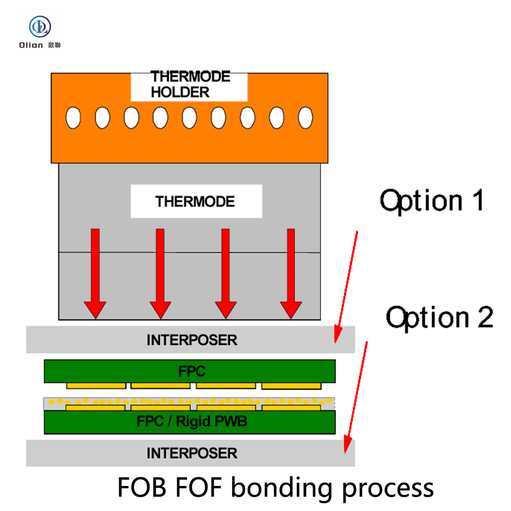
Hot Bar/Thermode
The Hot Bar or Thermode is the primary tool used to apply heat and pressure during the ACF bonding process. Hot bar bonding systems are designed to heat the hot bar to a specific temperature using low voltage electricity, which temperature is fed back to the controller via a thermocouple. The hot bar is brought into contact with the ACF film over the bonding pad, heated to the bonding temperature, and held for a specified time. This process produces the connection between the ACF tape and the components.
Bonding Heads
Bonding Heads are designed to hold the components and position the ACF tape correctly with the conductive pads on the PCB or other components. They ensure that the bonding process is accurate and consistent. Bonding heads can be manual or automated, depending on the specific requirements of the bonding process.
ACF Cutting Machines
ACF Cutting Machines are used to cut the ACF tape to the required length and shape. These machines ensure that the ACF tape is accurately cut and positioned for the bonding process. The cutting is done using the half-cut method, where only the actual ACF material is cut, and the cover-layer is used for tape transport.
Pre-Bonding and Final Bonding Machines
Pre-Bonding Machines are used to pre-bond ICs or COF on the panel that has been attached to the ACF. The pick and place of the panel is achieved manually, and the pre-alignment is automatically completed by the equipment.
Final Bonding Machines perform the main bonding on the LCD glass with IC, cable, or COF pre-pressed. The operator manually loads and unloads the products, while the ACF bonding is automatically performed by the machine.
Top-Bottom Alignment Bonding Machines
Top-Bottom Alignment Bonding Machines are used to bond FPC/Zebra paper on the PCB/Glass with the ACF attached. The pick and place and alignment of the PCB/Panel are done manually, and the ACF bonding is done automatically. These machines are suitable for 1″ to 12″ flat glass and flexible screen products bonding.
Fully Automatic ACF Bonding Line
A Fully Automatic ACF Bonding Line includes multiple machines working together to automate the entire bonding process. This includes substrates loading machines, terminal cleaning machines, fully automatic COG/COF/COP bonding machines, and fully automatic COF punching machines.
Testing and Inspection Equipment
Testing and Inspection Equipment is used to ensure the quality and reliability of the bonded products. This includes microscopes for surface inspection, temperature and pressure testers, and environmental testing chambers to simulate various conditions.
ACF Bonding Applications
ACF bonding is widely used in various industries, including mobile phone manufacturing, automotive, LCD production, mobile computers, TV manufacturing, open cell panels, touch panels, smart watches, and pads. It is also used in research labs focusing on LCD/LED/OLED/MICRO LED/MINI LED displays.
Benefits of ACF Bonding
ACF bonding offers several benefits, including:
Lead-free and environmentally friendly
Smallest pitch >30 micron possible
Flux-free process
No cleaning required after the process
Low process temperatures
High reliability and performance
Cost-effective compared to traditional connectors and soldering
In conclusion, the ACF bonding process relies on a suite of sophisticated parts and accessories to ensure the quality and reliability of the final products. Each component plays a critical role in different stages of the production process, from initial material preparation to final product testing. By using these parts and accessories, manufacturers can optimize their processes, reduce defects, and ensure that their products meet the highest standards of quality and performance.