• +86 18025364779
  • 2307972393@qq.com

Author Archive szolian

OL-FB1500A Fully Automatic FOG/FOF/TFOG Bonding Machine

OL-FB1500A Fully Automatic FOG/FOF/TFOG Bonding Machine

OL-FB1500A Fully Automatic FOG/FOF/TFOG Bonding Machine

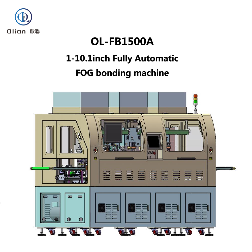
The OL-FB1500A is a state-of-the-art fully automatic FOG (Flexible On Glass)/FOF (Film On Film)/TFOG (Tape Film On Glass) bonding machine designed to meet the precise requirements of the modern electronics manufacturing industry. This advanced equipment is specifically tailored for the automatic ACF (Anisotropic Conductive Film) application, alignment, and thermal bonding of single-sided, single FPC (Flexible Printed Circuit) on LCD (Liquid Crystal Display) products ranging from 1″ to 10.1″ in size. Its innovative design and high-precision features make it an indispensable tool for manufacturers seeking efficiency, accuracy, and reliability in their production processes.

Equipment and Company Information

  • Equipment Name: Fully Automatic FOG/FOF/TFOG Bonding Machine
  • Model: OL-FB1500A
  • Application: Suitable for LCD products with sizes from 1″ to 10.1″, designed for automatic ACF application, alignment, and thermal bonding of single-sided, single FPC.
  • Compatibility: Can be integrated with other machines in a production line for seamless operation.

Working Principle

The OL-FB1500A operates through a series of coordinated mechanical and automated processes. The workflow begins with the loading of LCD + COF (Chip on Film) onto the conveyor belt or platform, either manually or via an automated upstream machine. The mechanical arm 0# picks up the LCD + COF and, after position correction by the CCD (Charge-Coupled Device) system, places it on the ACF platform. The ACF platform advances, and the bonding head descends to apply the ACF. After the ACF application, the platform retracts for position detection to ensure proper ACF adhesion.

Next, mechanical arm 1# transfers the LCD + COF to the pre-bonding stage while the FPC is simultaneously loaded and pre-aligned on the carrier stage. The bonding head then picks up the FPC and performs the pre-bonding process. Mechanical arm 2# moves the product to one of the four main bonding platforms for final bonding. Finally, mechanical arm 3# transfers the bonded product to the downstream conveyor or production line.

Product Specifications

LCD Specifications

  • Size Range: Minimum 20mm x 20mm, Maximum 230mm x 120mm, Thickness 0.15mm to 1.1mm.
  • Alignment Marks: Pitch ≥ 5mm between any two points on the glass, Mark size 2mm to 100mm.

FPC Specifications

  • Size Range: Minimum 20mm x 10mm, Maximum 150mm x 122mm, Thickness 0.1mm to 0.5mm.
  • Terminal Pitch: ≥ 50um.
  • Alignment Marks: Pitch 5mm to 70mm.
  • Customization: FPC width can be customized based on customer requirements and bonding head length.

ACF Specifications

  • Types: Roll-based, 2-layer or 3-layer.
  • Application Length: 5mm to 80mm.
  • Application Width: Available in 0.8mm, 1.0mm, 1.5mm, 2.0mm, and 2.5mm widths, adjustable according to requirements.
  • Reel Specifications: Inner diameter options of 18mm and 25mm, Maximum reel diameter 200mm.

Buffer Material Specifications

  • ACF Section: Single-piece buffer material, manually clamped.
  • Main Bonding Section: Automatic front-to-back rotation.
  • Reel Dimensions: Outer diameter ≤ 100mm, Inner hole diameter 32mm.
  • Width: Adjustable from 5mm to 20mm.
  • Feed Frequency: Adjustable from 1 to 999 cycles for automatic tape rotation.
  • Feed Length: Single-step length adjustable from 1mm to 130mm.

Machine Performance

Production Accuracy

  • ACF Application Accuracy: ±0.2mm in X-axis, ±0.15mm in Y-axis.
  • FPC Pre-bonding Accuracy: ±7um in X-axis, ±7um in Y-axis.
  • FPC Main Bonding Accuracy: ±10um in X-axis, ±15um in Y-axis.

Production Cycle

  • Cycle Time: ≤ 4.5 seconds per piece.
  • ACF Application Time: ≤ 0.5 seconds.
  • Pre-bonding Time: ≤ 0.5 seconds.
  • Main Bonding Time: ≤ 12 seconds.

Product Type

  • Supported Type: Single-sided, single FPC.

Model Changeover

  • New Model Setup: ≤ 60 minutes.
  • Existing Model Recall: ≤ 30 minutes, depending on the operator’s proficiency.

Process Parameter Specifications

Temperature Control

  • Setting Range:
    • ACF-bonding: Room Temperature (RT) to 120°C.
    • Pre-bonding: RT to 80°C.
    • Main-bonding: RT to 400°C.
  • Heating Method: Constant heat.
  • Control Method: Touchscreen setting with 0.1°C increments, PID control.
  • Temperature Uniformity: ±5°C.
  • Thermocouple Type: K type.

Time Setting

  • Setting Range:
    • ACF-bonding: 0.1 to 9.9 seconds.
    • Pre-bonding: 0.1 to 9.9 seconds.
    • Main-bonding: 0.1 to 99.9 seconds.
  • Setting Method: Configured via touchscreen interface with 0.1-second increments.

Pressure Control

  • Adjustment Range:
    • ACF-bonding: 10 to 150N.
    • Pre-bonding: 10 to 150N.
    • Main-bonding: 20 to 400N.
  • Control Method:
    • ACF and pre-bonding: Precision pressure regulator.
    • Main-bonding: Proportional valve with analog control, adjustable via touchscreen with 0.001Mpa increments.

General Machine Specifications

Dimensions and Weight

  • Machine Length: Approximately 2600mm (including 600mm conveyor extensions on both sides).
  • Machine Width: Approximately 1150mm.
  • Machine Height: Approximately 2000mm (including FFU and tri-color light).
  • Working Height: 1000mm.
  • Machine Weight: Approximately 2000kg.
  • Color: White, with customization options available.

Environmental and Power Requirements

  • Operating Environment: Class 1000 or lower cleanroom.
  • Power Supply: Single-phase 220VAC, with a 2-meter external power cord for connection to factory power (other interfaces available upon request).
  • Power Consumption: Maximum 8KW.
  • Air Supply:
    • Clean compressed air: Minimum pressure ≥ 0.5-0.7MPa.
    • Air consumption: Approximately 150L/min.
    • Air hose connection: 2-meter white hose with a 12mm diameter and quick connector for factory air supply.
  • Vacuum Supply:
    • Built-in vacuum pump (200L/min) and storage tank.
    • Optional external vacuum source with a 12mm diameter hose connection.
    • Vacuum level: ≥ -70Kpa (≥ 525mm Hg).
    • Vacuum flow: Approximately 150L/min.
    • Recommendation: Use the built-in vacuum pump if the external vacuum source is below 60.
  • Exhaust: Centralized exhaust through a silencer box.
  • Safety Features:
    • Emergency stop buttons with anti-misoperation covers.
    • Interlocked machine design for safety.
    • Audible and visual alarms on the touchscreen for error indication and operator alerts.

Equipment Unit Specifications

Feeding and Discharging

  • Feeding: Conveyor belt or platform loading.
  • Discharging: Conveyor belt unloading, with direct handover to downstream machines or production lines.

Robotic Arms

Mechanical Arm 1# (from Conveyor to ACF Platform):

Vacuum nozzles with adjustable numbers and configurations based on product size.

Digital vacuum gauge for real-time monitoring.

X-axis: Servo motor + ball screw drive.

θ-axis: Stepper motor.

Z-axis: Sliding table cylinder with manually adjustable position.

Mechanical Arm 2# (from ACF Stage to Pre-bonding Stage):

Vacuum nozzles with adjustable numbers and configurations based on product size.

Mechanical Arm 3# (from Pre-bonding Stage to Main Bonding Stage):

Mechanical Arm 4# (from Main Bonding Stage to Discharge Conveyor):

Vacuum nozzles with adjustable numbers and configurations based on product size.

Digital vacuum gauge for real-time monitoring.

X-axis: Linear motor drive.

Z-axis: Cylinder with manually adjustable position.

Sliding table cylinder with manually adjustable position.

ACF Unit

ACF Cutter:

Cutting Method: Automatic semi-cutting.

Depth Adjustment: Micrometer fine adjustment.

Blade Movement: Cylinder-driven up and down, with adjustable X-axis position.

ACF Head:

Number of Bonding Heads: 1.

Drive Method: Cylinder + rail.

Pressure Control: Cylinder control with precision pressure regulator.

Material: SUS440C (customizable).

Dimensions: W 6mm × L 60mm (customizable).

Surface Flatness: ≤ 5um.

ACF Stage:

X-axis Movement: Servo motor + ball screw + rail.

Y-axis Movement: Servo motor + ball screw + rail.

Vacuum: 1mm hole diameter, 2mm vacuum slot width.

Material: Aluminum with anodized hard oxidation treatment.

Flatness: ±0.02mm.

ACF Backup:

Material: Quartz.

Dimensions: L100mm × W10mm × H18mm.

Surface Flatness: ≤ 5um.

ACF Inspection: CCD inspection system.

ACF Supply:

Operation Method: Torque motor (or gravity hammer method).

Reel Tensioning: Belt tensioning structure.

Protective Film Recovery: Vacuum吸取 to waste bin.

Separation Rod Movement: Cylinder-driven rod.

FPC Pre-bonding Unit

Pre-bonding Head:

Number of Bonding Heads: 1.

Z-axis Drive: Servo motor + ball screw + rail.

Y-axis Transmission: Servo motor + ball screw + rail.

θ-axis Movement: DD motor.

Pressure Control: Cylinder control with precision pressure regulator.

Material: SUS 440C HRC58.

Dimensions: W 1.2mm × L 80mm (customizable).

Surface Flatness: ≤ ±5um.

Vacuum: Segmentable vacuum selection with vacuum detection.

Pre-bonding Stage:

X-axis Movement: Servo motor + ball screw + rail.

Y-axis Movement: Servo motor + ball screw + rail.

Vacuum: 1mm hole diameter, 2mm vacuum slot width.

Material: Aluminum with anodized hard oxidation treatment.

Flatness: ±0.02mm.

Pre-bonding Backup:

Material: Quartz.

Dimensions: L136mm × W10mm × H12mm (customizable).

Surface Flatness: ≤ ±5um.

FPC Supply:

Loading Method: Manual FPC loading or automatic FPC loader (purchased separately).

FPC Main Bonding Unit

Main Bonding Head:

Number of Bonding Heads: 4.

Drive Method: Cylinder + rail.

Pressure Control: Cylinder control with precision pressure regulator.

Material: SUS440C.

Dimensions: W 1.0mm × L 60mm (customizable).

Surface Flatness: ≤ ±4um.

Main Bonding Stage:

Y-axis Movement: Servo motor + ball screw.

Vacuum: 1mm hole diameter, 2mm vacuum slot width.

Material: Aluminum with anodized hard oxidation treatment.

Flatness: ±0.02mm.

Main Bonding Backup:

Material: Quartz strip.

Dimensions: L120mm × W6mm × H18mm.

Surface Flatness: ≤ ±5um.

Note: Vacuum position dimensions are customized based on FPC size.

Buffer Material Supply:

Rotation Method: Stepper motor drive.

Rotation Direction: Automatic front-to-back rotation.

Width Adjustment: Manual width adjustment with limit wheel.

Sensor detection for tape end monitoring.

Image Processing Unit

LCD Correction:

System: Bosch image processing system.

CCD Camera: 1.

Coaxial Light Barrel: 1.

Magnification: 1x.

Field of View: 4.8mm × 3.6mm.

Light Source: Coaxial light LED.

Z-axis Adjustable Travel: 10mm.

ACF Inspection:

System: Bosch image processing system.

CCD Camera: 1.

Coaxial Light Barrel: 1.

Magnification: 0.5x.

Field of View: 9.6mm × 7.2mm.

Light Source: Coaxial light LED.

Pre-bonding Alignment:

System: Bosch image processing system.

CCD Cameras: 2.

Coaxial Light Barrels: 2.

Magnification: 2x.

Field of View: 2.4mm × 1.8mm.

Light Source: Coaxial light LED.

Alignment Method: Coincidence point, with optional TFOG 4-camera configuration.

Main Bonding Alignment:

System: Bosch image processing system.

CCD Camera: 1.

Coaxial Light Barrel: 1.

Magnification: 1x.

Field of View: 4.8mm × 3.6mm.

Light Source: Coaxial light LED.

Z-axis Adjustable Travel: 10mm.

Control Unit

Control Method: PLC control.

Touchscreen:

Interface: Chinese, touch-enabled.

Modes: Manual and automatic.

Functions: Parameter display, data storage for 100 varieties.

Manual Control Buttons:

Emergency Stop Buttons: 3.

Main Power Switch: 1.

Lighting Power Switch: 1.

Access Control: Door opening function, machine pauses during operation.

Operation Indicator Lights: Tri-color lights.

Documentation and After-sales Service

Documentation: Machine operation manual included.

Training: Covers installation, operation, calibration, maintenance, troubleshooting, and safety precautions.

After-sales Service: One year of free service for non-human-induced faults, with lifelong technical support.

Main Component Brands

Servo Motors: Rite (China) / Yaskawa (Japan).

Ball Screws: Hiwin (China) / THK (Japan).

DD Motors: NSK (Japan).

Guideways: Hiwin (China) / THK (Japan).

Pneumatic Components: SMC (Japan) / Airtac (China).

PLC: Keyence (Japan).

Touchscreen: Proface (Japan).

Sensors: Panasonic (Japan) / HUAN (China).

Power Supply: Mean Well (Taiwan).

Circuit Breakers and Contactors: Schneider (France) / Shihlin (Taiwan).

Drag Chains: Igus (Germany).

Equipment 2D Drawing

A 2D drawing of the equipment is included for reference.

Image Processing Unit

The image processing unit of the FB-1500A is equipped with advanced systems to ensure precision in alignment and inspection processes. For LCD correction, it utilizes a Bosch image processing system with a CCD camera, coaxial light barrel, and LED light source. The system offers a field of view of 4.8mm × 3.6mm and allows for Z-axis adjustment over a 10mm travel range. Similarly, the ACF inspection part employs the same high-quality components to achieve a broader field of view of 9.6mm × 7.2mm, ensuring thorough and accurate quality checks.

In the pre-bonding alignment section, two CCD cameras and corresponding coaxial light barrels are used, providing a magnification of 2x and a field of view of 2.4mm × 1.8mm. This setup, combined with the Mark alignment method, guarantees precise positioning of components during the bonding process. The main bonding alignment part mirrors the LCD correction setup, ensuring consistency and accuracy throughout the machine’s operations.

Control Unit

The control unit is the brain of the FB-1500A, featuring PLC control for reliable and efficient operation. The touchscreen interface is user-friendly, offering both manual and automatic modes to cater to different production needs. It displays work parameters and can store data for up to 100 different product varieties, enhancing flexibility and streamlining production workflows.

Manual control buttons, including three emergency stop buttons, a main power switch, and a lighting power switch, provide operators with immediate control over the machine’s functions. The access control system ensures safety by pausing machine operation when doors are opened, and the tri-color operation indicator lights offer visual cues about the machine’s status.

Documentation and After-sales Service

Comprehensive documentation, including a detailed machine operation manual, is provided to guide users through setup, operation, and maintenance procedures. The training program covers a wide range of topics, from installation and parameter settings to equipment repair and common fault排除, ensuring operators are well-equipped to handle various scenarios.

After-sales service is a significant advantage of the FB-1500A, with one year of free service for non-human-induced faults and lifelong technical support. This commitment to customer satisfaction ensures that manufacturers can rely on the machine’s performance and receive assistance whenever needed.

Main Component Brands

The OL-FB1500A incorporates top-tier components from renowned brands worldwide. Servo motors from Rite and Yaskawa, ball screws from Hiwin and THK, and DD motors from NSK highlight the machine’s high-quality build. Pneumatic components from SMC and Airtac, along with PLC and touchscreen systems from Keyence and Proface, further underscore its reliability. Sensors from Panasonic and HUAN, power supplies from Mean Well, and circuit breakers from Schneider and Shihlin complete the list of premium parts that contribute to the machine’s exceptional performance.

Equipment 2D Drawing

A detailed 2D drawing of the OL-FB1500A is available, providing a clear visual representation of the machine’s layout and components. This drawing serves as a valuable reference for installation, maintenance, and integration into production lines.

In summary, the FB-1500A Fully Automatic FOG/FOF/TFOG Bonding Machine represents a significant advancement in the field of LCD manufacturing equipment. Its precise engineering, user-friendly design, and comprehensive support make it an ideal choice for manufacturers seeking to enhance productivity and product quality in the competitive electronics market.

OL-ECB1500A Fully Automatic EC+COG/COF Bonding Machine

OL-ECB1500A Fully Automatic EC+COG/COF Bonding Machine

OL-ECB1500A Fully Automatic EC+COG/COF Bonding Machine

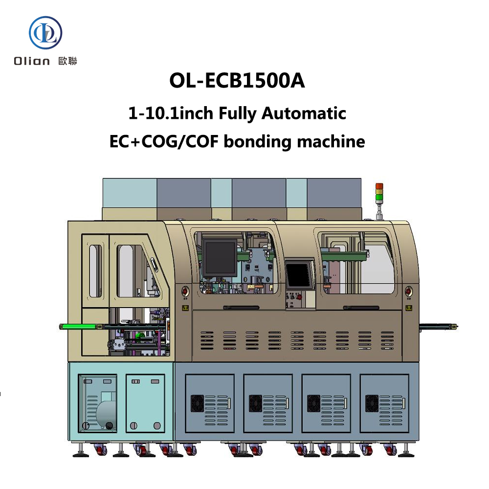
The OL-ECB1500A is a cutting-edge fully automatic EC+COG/COF bonding machine designed to meet the precise manufacturing requirements of modern electronics production. This advanced equipment is specifically tailored for the automatic wiping, ACF (Anisotropic Conductive Film) application, pre-bonding, and main bonding processes of single-sided, single-component LCD products ranging from 1″ to 10.1″ in size. Its innovative design and high-precision features make it an essential tool for manufacturers seeking efficiency, accuracy, and reliability in their production lines.

Equipment Information

  • Equipment Name: Fully Automatic EC+COG/COF Bonding Machine
  • Model: OL-ECB1500A
  • Application: Suitable for LCD products with sizes from 1″ to 10.1″, designed for automatic wiping, ACF application, pre-bonding, and main bonding of single-sided, single-component products.
  • Compatibility: Can be integrated with other machines in a production line for seamless operation.

Working Principle

The OL-ECB1500A operates through a series of coordinated mechanical and automated processes. The workflow begins with the loading of the product onto the conveyor belt or platform, either manually or via an automated upstream machine. Mechanical arm 1# picks up the product, corrects its position using the CCD (Charge-Coupled Device) system, and places it on the wiping platform. The wiping platform advances, and the wiping and plasma cleaning processes are completed across the entire wiping area.

Next, mechanical arm 2# transfers the LCD to the ACF platform. The ACF platform advances, and the bonding head descends to apply the ACF. After the ACF application, the platform retracts to the unloading position. Mechanical arm 3# then picks up the LCD, checks the ACF adhesion, and places it on the pre-bonding stage. Meanwhile, the IC/COF is loaded, and the automatic feeding system visually corrects the IC/COF position. After pre-alignment, the IC/COF is moved to the bonding head position, and the bonding head picks it up for pre-bonding. Mechanical arm 4# moves the product to one of the three main bonding platforms for final bonding. Finally, mechanical arm 5# transfers the bonded LCD to the downstream conveyor or production line.

Product Specifications

LCD Specifications

  • Size Range: Minimum 20mm x 20mm, Maximum 230mm x 120mm, Thickness 0.15mm to 1.1mm.
  • Alignment Marks: Pitch ≥ 5mm between any two points on the glass, Mark size 200µm to 800µm.

Cleaning Cloth Specifications

  • Type: Roll-based (number of rolls: 2).
  • Width: ≤ 10mm.
  • Maximum Roll Diameter: ≤ 300mm.
  • Roll Inner Hole Diameter: ≥ 24.5mm.
  • Feed Length: Adjustable from 0.1mm to 99.9mm.

Cleaning Solvent

  • Type: Alcohol or acetone.

IC/COF Specifications

  • Terminal Pitch: ≥ 30µm.
  • Alignment Marks: Pitch 5mm to 70mm.

ACF Specifications

  • Types: Roll-based, 2-layer or 3-layer.
  • Application Length: 5mm to 80mm (adjustable based on bonding head length and customer requirements).
  • Application Width: 0.5mm to 5.0mm.
  • Reel Specifications: Inner diameter options of 18mm and 25mm, Maximum reel diameter 200mm.

Buffer Material Specifications

  • ACF Section: Single-piece buffer material, manually clamped.
  • Main Bonding Section: Roll-based, automatic front-to-back rotation.
  • Reel Dimensions: Outer diameter ≤ 100mm, Inner hole diameter 32mm.
  • Width: Adjustable from 5mm to 20mm.
  • Feed Frequency: Adjustable from 1 to 999 cycles for automatic tape rotation.
  • Feed Length: Single-step length adjustable from 1mm to 99mm.

Machine Performance

Water Drop Angle

  • Water Drop Angle: ≤ 25 degrees, depending on actual conditions.

Production Accuracy

  • ACF Application Accuracy: ±0.2mm in X-axis, ±0.15mm in Y-axis.
  • IC/COF Pre-bonding Accuracy: ±3µm in X-axis, ±3µm in Y-axis.
  • IC/COF Main Bonding Accuracy: ±5µm in X-axis, ±5µm in Y-axis (related to COF material expansion coefficient).

Production Cycle

  • Cycle Time: ≤ 4.5-5 seconds per piece.
  • ACF Application Time: ≤ 0.5 seconds.
  • Pre-bonding Time: ≤ 0.5 seconds.
  • Main Bonding Time: ≤ 12 seconds.
  • Variation based on product size.

Product Type

  • Supported Type: Single-sided, single IC/COF.

Model Changeover

  • New Model Setup: ≤ 60 minutes.
  • Existing Model Recall: ≤ 30 minutes, depending on the operator’s proficiency.

Equipment Yield

  • Yield: ≥99.5% (excluding material issues).

Process Parameter Specifications

Temperature Control

  • Setting Range:
    • ACF-bonding: Room Temperature (RT) to 150°C.
    • Pre-bonding: RT to 150°C.
    • Main-bonding: RT to 400°C.
  • Heating Method: Constant heat.
  • Control Method: Touchscreen setting with 0.1°C increments, PID control.
  • Temperature Uniformity: ±5°C.
  • Thermocouple Type: K type.

Time Setting

  • Setting Range:
    • ACF-bonding: 0.1 to 9.9 seconds.
    • Pre-bonding: 0.1 to 9.9 seconds.
    • Main-bonding: 0.1 to 99.9 seconds.
  • Setting Method: Configured via touchscreen interface with 0.1-second increments.

Pressure Control

  • Adjustment Range:
    • ACF-bonding: 10 to 150N.
    • Pre-bonding: 10 to 150N.
    • Main-bonding: 20 to 400N.
  • Control Method:
    • ACF and pre-bonding: Precision pressure regulator.
    • Main-bonding: Proportional valve with analog control, adjustable via touchscreen with 0.002Mpa increments.

General Machine Specifications

Dimensions and Weight

  • Machine Length: Approximately 3210mm (including 620mm conveyor extension).
  • Machine Width: Approximately 1400mm.
  • Machine Height: Approximately 1800mm (excluding FFU and tri-color light).
  • Working Height: 1000mm.
  • Machine Weight: Approximately 3500kg.
  • Color: White, with customization options available.

Environmental and Power Requirements

  • Operating Environment: Class 1000 or lower cleanroom.
  • Power Supply: Single-phase, AC 220V±10%, 50 Hz, with a 2-meter external power cord for connection to factory power (other interfaces available upon request).
  • Power Consumption: Maximum 10KW.
  • Air Supply:
    • Clean compressed air: Minimum pressure ≥ 0.5-0.7MPa.
    • Air consumption: Approximately 150L/min.
    • Air hose connection: 2-meter white hose with a 12mm diameter and quick connector for factory air supply.
  • Vacuum Supply:
    • Built-in vacuum pump (200L/min) and storage tank.
    • Optional external vacuum source with a 12mm diameter hose connection.
    • Vacuum level: ≥ -70Kpa (≥ 525mm Hg).
    • Vacuum flow: Approximately 150L/min.
    • Recommendation: Use the factory vacuum system if available.
  • Exhaust: Centralized exhaust system.
  • Safety Features:
    • Emergency stop buttons with anti-misoperation covers.
    • Interlocked machine design for safety.
    • Audible and visual alarms on the touchscreen for error indication and operator alerts.
    • Safety labels (electric shock, mechanical injury, etc.) and hazard area warnings.

Equipment Unit Specifications

Feeding and Discharging

  • Feeding: Conveyor belt or platform loading.
  • Discharging: Conveyor belt unloading, with direct handover to downstream machines or production lines.

Solvent Supply Unit

  • Solvent Control: Dosed by peristaltic dispensing equipment.
  • Solvent Drop Volume: Adjustable per drop.

Cleaning Cloth Supply Unit

  • Cleaning Cloth Movement: Stepper motor + polyurethane roller.
  • Cleaning Cloth Tensioning: Magnetic damping, adjustable force.
  • Cleaning Cloth Recycling: Torque motor + magnetic damping, roll-based recycling.
  • Cleaning Cloth Length Control: Stepper motor, adjustable length via operation interface.
  • End-of-Tape Detection: Sensor detects when the cleaning cloth roll is finished.

Cleaning Air Claw Unit

  • Air Claw Gap Height: Adjustable via micrometer, travel 5mm.
  • Air Claw Flatness: Adjustable relative flatness of upper and lower clamping surfaces.

PLAMA Unit

  • Plasma Cleaning: Low-temperature plasma, measured around 100°C.

Robotic Arms

  • Mechanical Arm 1# (from Feeding Conveyor to Wiping Platform):
    • Vacuum nozzles with adjustable numbers and configurations based on product size.
    • Digital vacuum gauge for real-time monitoring.
    • X-axis: Servo motor + ball screw rail.
    • θ-axis: Stepper motor.
    • Z-axis: Sliding table cylinder with manually adjustable position.
    • Completes product correction and transfer to the next process.
  • Mechanical Arm 2# (from Wiping Stage to ACF Stage):
    • Vacuum nozzles with adjustable numbers and configurations based on product size.
    • Digital vacuum gauge for real-time monitoring.
    • X-axis: Servo motor + ball screw rail.
    • θ-axis: Stepper motor for next-process angle adjustment.
  • Mechanical Arm 3# (from ACF Stage to Pre-bonding Stage):
    • Vacuum nozzles with adjustable numbers and configurations based on product size.
    • Digital vacuum gauge for real-time monitoring.
    • X-axis: Linear motor + rail.
    • θ-axis: Stepper motor for next-process angle adjustment.
  • Mechanical Arm 4# (from Pre-bonding Stage to Main Bonding Platform):
    • Vacuum nozzles with adjustable numbers and configurations based on product size.
    • Digital vacuum gauge for real-time monitoring.
    • X-axis: Linear motor + rail.
    • θ-axis: Stepper motor for next-process angle adjustment.
  • Mechanical Arm 5# (from Main Bonding Stage to Discharge Conveyor):
    • Vacuum nozzles with adjustable numbers and configurations based on product size.
    • Digital vacuum gauge for real-time monitoring.
    • X-axis: Linear motor + rail.
    • θ-axis: Stepper motor for next-process angle adjustment.

ACF Unit

  • ACF Cutter:
    • Cutting Method: Automatic semi-cutting.
    • Depth Adjustment: Micrometer fine adjustment.
    • Blade Movement: Cylinder-driven up and down, with adjustable X-axis position.
  • ACF Head:
    • Number of Bonding Heads: 1.
    • Drive Method: Cylinder + rail.
    • Pressure Control: Cylinder control with precision pressure regulator.
    • Material: SUS440C (customizable).
    • Dimensions: W 2mm × L 70mm (customizable).
    • Surface Flatness: ≤ 5µm.
  • ACF Stage:
    • X-axis Movement: Servo motor + ball screw + rail.
    • Y-axis Movement: Servo motor + ball screw + rail.
    • Z-axis Movement: Servo motor + ball screw + rail.
    • Vacuum: 1mm hole diameter, 2mm vacuum slot width.
    • Material: Aluminum with anodized hard oxidation treatment.
    • Flatness: ±0.02mm.
  • ACF Backup:
    • Material: Quartz.
    • Dimensions: L100mm × W10mm × H18mm.
    • Surface Flatness: ≤ 5µm.
  • ACF Inspection: CCD inspection system.
  • ACF Supply:
    • Operation Method: Torque motor (or gravity hammer tensioning).
    • Reel Tensioning: Belt tensioning structure.
    • Protective Film Recovery: Vacuum吸取 to waste bin.
    • Separation Rod Movement: Cylinder-driven rod.

IC/COF Pre-bonding Unit

  • Pre-bonding Head:
    • Number of Bonding Heads: 1.
    • Z-axis Drive: Servo motor + ball screw + rail.
    • Y-axis Transmission: Servo motor + ball screw + rail.
    • θ-axis Movement: DD motor.
    • Pressure Control: Cylinder control with precision pressure regulator.
    • Material: SUS 440C.
    • Dimensions: W 1.2mm × L 80mm (customizable).
    • Surface Flatness: ≤ ±3µm.
    • Vacuum: Segmentable vacuum selection with vacuum detection.
  • Pre-bonding Stage:
    • X-axis Movement: Servo motor + ball screw + rail.
    • Y-axis Movement: Servo motor + ball screw + rail.
    • Z-axis Movement: Servo motor + ball screw + rail.
    • Vacuum: 1mm hole diameter, 2mm vacuum slot width.
    • Material: Aluminum with anodized hard oxidation treatment.
    • Flatness: ±0.02mm.
  • Pre-bonding Backup:
    • Material: Quartz strip.
    • Dimensions: L136mm × W10mm × H12mm.
    • Surface Flatness: ≤ ±5µm.

IC/COF Main Bonding Unit

  • Main Bonding Head:
    • Number of Bonding Heads: 3.
    • Drive Method: Servo motor + cylinder + rail.
    • Pressure Control: Cylinder control with proportional valve analog control, adjustable via touchscreen.
    • Material: SUS440C.
    • Dimensions: W 5.0mm × L 60mm (customizable).
    • Surface Flatness: ≤ ±3µm.
  • Main Bonding Stage:
    • Y-axis Movement: Servo motor + ball screw + rail.
    • Z-axis Movement: Servo motor + ball screw + rail.
    • Vacuum: 1mm hole diameter, 2mm vacuum slot width.
    • Material: Aluminum with anodized hard oxidation treatment.
    • Flatness: ±0.02mm.
  • Main Bonding Backup:
    • Material: Quartz.
    • Dimensions: L80mm × W12mm × H18mm.
    • Surface Flatness: ≤ ±2µm.
  • Buffer Material Supply:
    • Rotation Method: Stepper motor drive.
    • Rotation Direction: Automatic front-to-back rotation.
    • Width Adjustment: Manual width adjustment with limit wheel.
    • Sensor detection for tape end monitoring.

Image Processing Unit

  • LCD Feeding Correction:
    • System: Bos视 image processing system.
    • CCD: 1.
    • Coaxial Light Barrel: 1.
    • Magnification: 1x.
    • Field of View: 4.8mm × 3.6mm.
    • Light Source: Coaxial light LED.
    • Z-axis Adjustable Travel: 10mm.
  • ACF Pre-correction:
    • System: Bos视 image processing system.
    • CCD: 1.
    • Coaxial Light Barrel: 1.
    • Magnification: 1x.
    • Field of View: 4.8mm × 3.6mm.
    • Light Source: Coaxial light LED.
    • Z-axis Adjustable Travel: 10mm.
  • ACF Inspection:
    • System: Bosch image processing system.
    • CCD Camera: 1.
    • Coaxial Light Barrel: 1.
    • Magnification: 0.5x.
    • Field of View: 9.6mm × 7.2mm.
    • Light Source: Coaxial light LED.
  • IC Feeding Correction:
    • System: Bosch image processing system.
    • CCD Camera: 1.
    • Coaxial Light Barrel: 1.
    • Magnification: 1x.
    • Field of View: 4.8mm × 3.6mm.
    • Light Source: Coaxial light LED.
  • Pre-bonding Alignment:
    • System: Bos视 image processing system.
    • CCD Cameras: 2.
    • Coaxial Light Barrels: 2.
    • Magnification: 4x.
    • Field of View: 1.2mm × 0.9mm.
    • Light Source: Coaxial light LED.
    • Alignment Method: Mark coincidence.
  • Main Bonding Alignment:
    • System: Bos视 image processing system.
    • CCD Camera: 1.
    • Coaxial Light Barrel: 1.
    • Magnification: 1x.
    • Field of View: 4.8mm × 3.6mm.
    • Light Source: Coaxial light LED.
    • Z-axis Adjustable Travel: 10mm.
    • X-axis: Servo motor + ball screw + rail.

Control Unit

  • Control Method: PLC control.
  • Touchscreen:
    • Interface: Chinese, touch-enabled.
    • Modes: Manual and automatic.
    • Functions: Parameter display.
  • Manual Control Buttons:
    • Emergency Stop Buttons: 3.
    • Main Power Switch: 1.
    • Lighting Power Switch: 1.
  • Access Control: Door opening function, machine pauses during operation.
  • Operation Indicator Lights: Tri-color lights.

Documentation and After-sales Service

  • Documentation: Machine operation manual included.
  • Training: Covers installation, operation, calibration, maintenance, troubleshooting, and safety precautions.
  • After-sales Service: One year of free service for non-human-induced faults, with lifelong technical support.

Main Component Brands

  • Servo Motors: Rite (China) / Yaskawa (Japan).
  • Ball Screws: Hiwin (China) / THK (Japan).
  • DD Motors: NSK (Japan).
  • Guideways: Hiwin (China) / THK (Japan).
  • Pneumatic Components: SMC (Japan) / Fujikura (Japan) / Airtac (China).
  • PLC: Keyence (Japan).
  • Touchscreen: Proface (Japan).
  • Sensors: Panasonic (Japan) / HUAN (China).
  • Power Supply: Mean Well (Taiwan).
  • Circuit Breakers and Contactors: Schneider (France) / Shihlin (Taiwan).
  • Drag Chains: Igus (Germany).

Equipment 2D Drawing

A detailed 2D drawing of the equipment is available, providing a clear visual representation of the machine’s layout and components. This drawing serves as a valuable reference for installation, maintenance, and integration into production lines.

In summary, the OL-ECB1500A Fully Automatic EC+COG/COF Bonding Machine represents a significant advancement in the field of LCD manufacturing equipment. Its precise engineering, user-friendly design, and comprehensive support make it an ideal choice for manufacturers seeking to enhance productivity and product quality in the competitive electronics market.

OL-CC1000A Fully Automatic COF Punch & Feed Machine

OL-CC1000A Fully Automatic COF Punch & Feed Machine

OL-CC1000A Fully Automatic COF Punch & Feed Machine

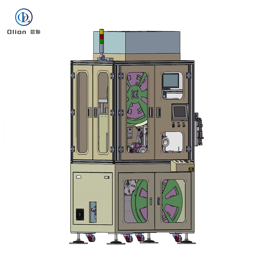
The OL-CC1000A Fully Automatic COF Punch & Feed Machine is a highly advanced fully automatic COF (Chip on Film) punching and feeding machine designed to meet the precise requirements of modern electronics manufacturing. This equipment specializes in processing COF products with widths of 35mm, 48mm, and 70mm, ensuring accuracy and efficiency in production environments. Its innovative design and robust performance make it an essential addition to manufacturing lines, particularly when integrated with other bonding equipment for seamless operation.

Equipment Information

  • Equipment Name: Fully Automatic COF Punch & Feed Machine
  • Model: OL-CC1000A
  • Application: Designed for COF products with widths of 35mm, 48mm, and 70mm.
  • Compatibility: Can be integrated with other bonding machines for automated production lines.

Machine Specifications

Physical and Environmental Specifications

  • Dimensions:
    • Length: 800mm
    • Width: 1100mm
    • Height: 2090mm (excluding FFU)
  • Weight: Approximately 300kg
  • Color: Off-white (customizable to client specifications)
  • Operating Environment: Requires a Class 1000 or lower cleanroom.
  • Power Supply: Single-phase AC 220V±10%, 50 Hz, with a 2-meter power cord for connection to factory power.
  • Power Consumption: Maximum 4KW
  • Air Supply:
    • Clean compressed air with a minimum pressure of 0.5-0.7MPa.
    • Air consumption: Approximately 20L/min.
    • Equipped with a 2-meter long white air hose with a quick connector for factory air supply.
  • Vacuum Supply:
    • Consumption: 20L/min.
    • Optional customer-provided vacuum source with a 12mm diameter hose connection.
    • Vacuum level: ≥ -70Kpa (≥ 525mm Hg).
  • Exhaust System: Centralized exhaust.
  • Safety Features:
    • Emergency stop buttons with protective covers to prevent accidental activation.
    • Interlocked machine design with protective devices.
    • Audible and visual alarms via the touchscreen for errors or operator alerts.
    • Safety labels and hazard area warnings for electrical shock and mechanical injury risks.

Unit Specifications

COF Supply Unit

  • COF Material Specifications:
    • Reel outer diameter: Φ405-600mm ABS reel.
    • Inner diameter: Φ25.4mm.
    • Tape widths: 35mm (34980±200um), 48mm (48180±200um), 70mm (69950±200um).
    • Tape thickness: 50-125um.
    • Types: Standard, Wide, Super Wide.
    • Warp: ≤ 2mm.
    • Dimensions: 5-30mm (L) × 7-42mm (W).
    • Maximum height difference of components: ≤ 0.5mm.
    • Pitch of positioning holes: 4.75mm; hole size: 1.42±0.02mm.
  • COF Feeding Mechanism:
    • Motor-driven with tape tensioning mechanism.
    • Tape transmission via ratchet mechanism.
    • Fiber optic detection at the die inlet for COF tape and IC presence.
  • COF Punching and Waste Tape Recycling:
    • Punching driven by cylinders with die cutting.
    • Waste tape回收 via stepper motor and tensioning mechanism.
    • Punching accuracy: ±50um (requires COF tape accuracy ≤±15um and die accuracy ≤±5um).
    • For 70mm tape width, dimensions must meet: A+B≥6mm, C≤55mm, D≥1.2mm, E≥28mm, F≥4mm, G≥50um.
    • Alternative punching accuracy: ±80um (requires COF tape accuracy ≤±15um and die accuracy ≤±10um).
    • For 70mm tape width, dimensions: A+B=3-5.9mm, C=55-60mm, D=0 (no reinforcing plate), E=10-28mm, F=1.2-4mm, G=15-50um.
  • COF Cleaning and Transmission:
    • Driven by servo motor, ball screw, and rail.
    • Digital vacuum gauge with adjustable and monitorable vacuum levels.
    • Cleaning unit with anti-static brush and motor/stepper motor.
    • COF picking using flexible material.
  • COF Receiving Platform:
    • Driven by servo motor, ball screw, and rail.
    • Digital vacuum gauge with adjustable and monitorable vacuum levels.
  • Punch Die:
    • Purchased externally or provided by the user.
    • Die life: Approximately 300,000 cycles (exact data from the mold supplier).

Vision System Unit

  • COF Feeding Correction:
    • Image processing system: Bos视.
    • CCD Camera: 1.
    • Coaxial light barrel: 1.
    • Magnification: 1x.
    • Field of view: 4.8mm × 3.6mm.
    • Light source: Coaxial light LED.

Control Unit

  • Control Method: PLC control.
  • Touchscreen:
    • Interface: Chinese, touch-enabled.
    • Modes: Manual and automatic.
    • Functions: Parameter display.
  • Manual Control Buttons:
    • Emergency stop button: 1.
    • Main power switch: 1.
  • Access Control: Door opening function, machine pauses during operation.
  • Operation Indicator Lights: Tri-color lights.

Documentation and After-sales Service

  • Documentation: Machine operation manual included.
  • Training: Covers installation, operation, calibration, maintenance, troubleshooting, and safety precautions.
  • After-sales Service: One year of free service for non-human-induced faults, with lifelong technical support.

In summary, the OL-CC-1000A Fully Automatic COF Punch & Feed Machine is a state-of-the-art solution for COF product manufacturing. Its precision, reliability, and user-friendly design make it an invaluable asset for electronics manufacturers looking to optimize their production processes and enhance product quality.

OL-LLD1000 Fully Automatic LCD Loader

OL-LLD1000 Fully Automatic LCD Loader

OL-LLD1000 Fully Automatic LCD Loader

The OL-LLD1000 is a cutting-edge fully automatic LCD loader designed to efficiently load LCD panels of various sizes using a TRAY disk transmission method. This advanced machine is compatible with other equipment for automated production lines, making it a valuable addition to modern manufacturing environments where precision and speed are paramount.

Equipment Information

  • Equipment Name: Fully Automatic LCD Loader
  • Model: OL-LLD1000
  • Function: Loads LCD panels automatically via TRAY disk transmission, compatible with other devices for integrated use.

Working Principle

The OL-LLD1000 operates through a well-coordinated process. It starts with manual placement of loaded TRAY disks (containing LCD panels) onto the loading position. The full TRAY disk is then lifted by the Z-axis to the pick-up position. The product robotic arm picks up the LCD panels and places them onto the downstream discharge position. Simultaneously, the tray robotic arm transfers empty trays to the empty TRAY disk warehouse, ensuring a continuous and efficient workflow.

Product Specifications

LCD Specifications

  • Size Range: Minimum 45×72mm, Maximum 95×160mm.

Tray Disk Specifications

  • Dimensions: Maximum 400×460mm, Minimum 250×220mm.

Machine Performance

Production Cycle

  • Cycle Time: ≤4 seconds per piece, ensuring high throughput and efficiency.

General Machine Specifications

Dimensions and Weight

  • Machine Length: 1150mm.
  • Machine Width: 1000mm.
  • Machine Height: 1700mm (excluding tri-color light: 350mm).
  • Weight: Approximately 300kg.
  • Color: Off-white with chrome or oxidation treatment on some components (customizable to client requirements).

Environmental and Power Requirements

  • Operating Environment: Requires a clean, dust-free room.
  • Power Supply: Single-phase AC 220V±10%, 50 Hz, with a 2-meter power cord for connection to factory power.
  • Power Consumption: Maximum 2000W.

Air and Vacuum Supply

  • Air Supply: Clean compressed air with a minimum pressure of 0.5-0.7MPa, consumption approximately 100L/min.
  • Vacuum Supply: Minimum vacuum degree of -70Kpa, flow approximately 100L/min.

Safety Features

  • Emergency Stop: Equipped with anti-misoperation covers.
  • Interlocked Design: Ensures machine safety during operation.
  • Audible and Visual Alarms: Alerts for errors or operator attention via the touchscreen.
  • Safety Labels: Warnings for electrical shock, mechanical injury, etc., in hazard areas.

Equipment Unit Specifications

Full/Empty Tray Handling

  • Elevation Mechanism: Stepper motor + precision ball screw.
  • Tray Stacking: Up to 600mm in height on the elevation platform.
  • Positioning: Mechanical positioning for accuracy.

LCD XYZ Transport Robotic Arm and Tray X Robotic Arm

  • Drive: XY axes by servo motor, Z axis by cylinder.
  • Precision: ±0.05mm movement accuracy.
  • Vacuum System: Adjustable vacuum nozzles with digital vacuum gauge for real-time monitoring.

Control Unit

  • Control Method: PLC control for reliability.
  • Touchscreen: User-friendly Chinese interface with manual and automatic modes, displaying work parameters.
  • Manual Control Buttons: Includes emergency stop, main power, and control buttons.
  • Access Control: Machine pauses when doors are opened during operation.
  • Indicator Lights: Tri-color lights for machine status indication.

Documentation and After-sales Service

  • Training: Covers installation, operation, calibration, maintenance, troubleshooting, and safety precautions.
  • After-sales Service: One year of free service for non-human-induced faults, with lifelong technical support.

Main Component Brands

  • Servo and Stepper Motors: Rite (China).
  • Modules: SKD (China).
  • Guideways: Hiwin (China).
  • Pneumatic Components: Airtac (China).
  • PLC: Panasonic (Japan).
  • Touchscreen: Proface (Japan).
  • Power Supply: Mean Well (China).
  • Circuit Breakers and Contactors: Shihlin (China).
  • Drag Chains: Igus (Germany).
  • Emergency Stop and Switch Buttons: Schneider (China).
  • FFU (Stainless Steel): Yunfeng (China).

In summary, the OL-LLD1000 Fully Automatic LCD Loader is a state-of-the-art solution for LCD panel loading in modern manufacturing. Its precision, speed, and user-friendly design make it an invaluable asset for electronics manufacturers looking to optimize their production processes and enhance product quality.

OL-FLD1000B Fully Automatic FPC Loader

OL-FLD1000B Fully Automatic FPC Loader

OL-FLD1000B Fully Automatic FPC Loader

The OL-FLD1000B is a state-of-the-art fully automatic FPC (Flexible Printed Circuit) loader designed to efficiently load FPCs of various sizes using a TRAY disk transmission method. This advanced machine can be integrated with FOG (Film on Glass) equipment for automated production lines, making it a valuable addition to modern manufacturing environments where precision and speed are critical.

Equipment Information

  • Equipment Name: Fully Automatic FPC Loader
  • Model: OL-FLD1000B
  • Function: Loads FPCs automatically via TRAY disk transmission, compatible with FOG devices for integrated use.

Working Principle

The OL-FLD1000B operates through a well-coordinated process. It starts with manual placement of loaded TRAY disks (containing FPCs) onto the loading position. The Tray loading handling Z-axis lifts a TRAY disk to the intermediate platform. After a full-view photo is taken, the FPC handling XYZθ-axis robotic arm picks up the FPC from the Tray and moves it to the discharge position. The Tray intermediate platform then moves to the unloading position, where the Tray unloading handling Z-axis removes the empty Tray and places it in the empty Tray unloading position, ensuring a continuous and efficient workflow.

Product Specifications

FPC Specifications

  • Size Range: Minimum 15×10mm, Maximum 100×175mm.

Tray Disk Specifications

  • Dimensions: Maximum 400×460mm, Minimum 250×220mm.

Machine Performance

Production Cycle

  • Cycle Time: ≤4.5 seconds per piece, ensuring high throughput and efficiency.

Handling Precision

  • Precision: ±0.03mm, with movement accuracy of ±0.05mm for the FPC handling robotic arm.

General Machine Specifications

Dimensions and Weight

  • Machine Length: 1100mm.
  • Machine Width: 1100mm (with a 240mm extension for the robotic arm).
  • Machine Height: 1760mm (excluding tri-color light: 350mm).
  • Weight: Approximately 400kg.
  • Color: Off-white with chrome or oxidation treatment on some components (customizable to client requirements).

Environmental and Power Requirements

  • Operating Environment: Requires a clean, dust-free room.
  • Power Supply: Single-phase AC 220V±10%, 50 Hz, with a 2-meter power cord for connection to factory power.
  • Power Consumption: Maximum 2000W.

Air and Vacuum Supply

  • Air Supply: Clean compressed air with a minimum pressure of 0.5-0.7MPa, consumption approximately 100L/min.
  • Vacuum Supply: Minimum vacuum degree of -70Kpa, flow approximately 100L/min.

Safety Features

  • Emergency Stop: Equipped with anti-misoperation covers.
  • Interlocked Design: Ensures machine safety during operation.
  • Audible and Visual Alarms: Alerts for errors or operator attention via the touchscreen.
  • Safety Labels: Warnings for electrical shock, mechanical injury, etc., in hazard areas.

Equipment Unit Specifications

Full/Empty Tray Handling

  • Elevation Mechanism: Servo motor + precision ball screw.
  • Tray Stacking: Up to 500mm in height on the elevation platform.
  • Positioning: Mechanical positioning for accuracy.

Tray X-axis Intermediate Transfer

  • Positioning: Mechanical positioning for Tray disks.
  • Drive: Servo motor with ball screw transmission, using precision linear guides.
  • Precision: ±0.02mm movement accuracy.

Tray Disk Handling Structure

  • Drive: Cylinder-driven.
  • Vacuum System: Adjustable vacuum nozzles with digital vacuum gauge for real-time monitoring.

FPC XYZθ Handling Robotic Arm

  • Drive: XYZ axes by servo motor, θ-axis by stepper motor.
  • Precision: ±0.05mm movement accuracy.
  • Vacuum System: Adjustable vacuum nozzles with digital vacuum gauge for real-time monitoring.

Control Unit

  • Control Method: PLC control for reliability.
  • Touchscreen: User-friendly Chinese interface with manual and automatic modes, displaying work parameters.
  • Manual Control Buttons: Includes emergency stop, main power, and control buttons.
  • Access Control: Machine pauses when doors are opened during operation.
  • Indicator Lights: Tri-color lights for machine status indication.

Training and After-sales Service

  • Training: Covers installation, operation, calibration, maintenance, troubleshooting, and safety precautions.
  • After-sales Service: One year of free service for non-human-induced faults, with lifelong technical support.

Main Component Brands

  • Servo and Stepper Motors: Manufactured in China.
  • Guideways: Hiwin (China).
  • Modules: SKD (China).
  • Pneumatic Components: Airtac (China).
  • PLC: Panasonic (Japan).
  • Touchscreen: Proface (Japan).
  • Power Supply: Mean Well (China).
  • Circuit Breakers and Contactors: Schneider (China).
  • Drag Chains: Igus (Germany).
  • Emergency Stop and Switch Buttons: Schneider (China).
  • FFU (Stainless Steel): Yunfeng (China).

In summary, the OL-FLD1000B Fully Automatic FPC Loader is a cutting-edge solution for FPC loading in modern manufacturing. Its precision, speed, and user-friendly design make it an invaluable asset for electronics manufacturers looking to optimize their production processes and enhance product quality.

is a highly advanced fully automatic EC+COG (Chip on Glass) bonder designed to meet the precise manufacturing requirements of modern electronics production

OL-ECB800 Fully Automatic EC+COG Bonder

OL-ECB800 Fully Automatic EC+COG Bonder

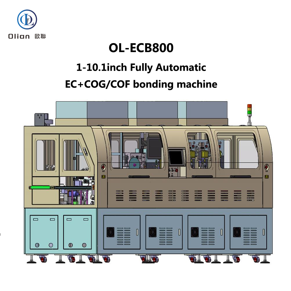
The OL-ECB800 is a highly advanced fully automatic EC+COG (Chip on Glass) bonder designed to meet the precise manufacturing requirements of modern electronics production. This machine specializes in automatic wiping, ACF (Anisotropic Conductive Film) application, pre-bonding, and main bonding processes for LCD products ranging from 1″ to 10.1″ in size. Its innovative design and high-precision features make it an essential tool for manufacturers seeking efficiency, accuracy, and reliability in their production lines.

Equipment Information

  • Equipment Name: Fully Automatic EC+COG Bonder
  • Model: OL-ECB800
  • Application: Suitable for LCD products with sizes from 1″ to 10.1″, designed for automatic wiping, ACF application, pre-bonding, and main bonding of single-sided, single-segment products.
  • Compatibility: Can be integrated with other machines in a production line for seamless operation.

Working Principle

The OL-ECB800 operates through a series of coordinated mechanical and automated processes. The workflow begins with the loading of the product onto the conveyor belt or platform, either manually or via an automated upstream machine. Mechanical arm 1# picks up the product, corrects its position using the CCD (Charge-Coupled Device) system, and places it on the wiping platform. The wiping platform advances, and the wiping and plasma cleaning processes are completed across the entire wiping area.

Next, mechanical arm 2# transfers the LCD to the ACF platform. The ACF platform advances, and the bonding head descends to apply the ACF. After the ACF application, the platform retracts to the unloading position. Mechanical arm 3# then picks up the LCD, checks the ACF adhesion, and places it on the pre-bonding stage. Meanwhile, the IC is loaded, and the automatic feeding system visually corrects the IC position. After pre-alignment, the IC is moved to the bonding head position, and the bonding head picks it up for pre-bonding. Mechanical arm 4# moves the product to one of the three main bonding platforms for final bonding. Finally, mechanical arm 5# transfers the bonded LCD to the downstream conveyor or production line.

Product Specifications

LCD Specifications

  • Size Range: Minimum 20mm x 15mm, Maximum 230mm x 165mm, Thickness 0.15mm to 1.1mm.
  • Alignment Marks: Pitch 5-35mm between any two points on the glass, Mark size 200µm to 1000µm.

Cleaning Cloth Specifications

  • Type: Roll-based (number of rolls: 2).
  • Width: ≤ 10mm.
  • Maximum Roll Diameter: ≤ 300mm.
  • Roll Inner Hole Diameter: ≥ 24.5mm.
  • Feed Length: Adjustable from 0.1mm to 99.9mm.

Cleaning Solvent

  • Type: Alcohol or acetone.

IC Specifications

  • Terminal Pitch: ≥ 20µm.
  • Alignment Marks: Pitch 5mm to 70mm.

ACF Specifications

  • Types: Roll-based, 2-layer or 3-layer.
  • Application Length: 5mm to 80mm (adjustable based on bonding head length and customer requirements).
  • Application Width: 0.5mm to 5.0mm.
  • Reel Specifications: Inner diameter options of 18mm and 25mm, Maximum reel diameter 200mm.

Buffer Material Specifications

  • ACF Section: Single-piece buffer material, manually clamped.
  • Main Bonding Section: Roll-based, automatic front-to-back rotation.
  • Reel Dimensions: Outer diameter ≤ 100mm, Inner hole diameter 32mm.
  • Width: Adjustable from 5mm to 20mm.
  • Feed Frequency: Adjustable from 1 to 999 cycles for automatic tape rotation.
  • Feed Length: Single-step length adjustable from 1mm to 99mm.

Machine Performance

Water Drop Angle

  • Water Drop Angle: ≤ 20 degrees (PT300 ultra-low temperature plasma), depending on actual conditions.

Production Accuracy

  • ACF Application Accuracy: ±0.2mm in X-axis, ±0.15mm in Y-axis.
  • IC Pre-bonding Accuracy: ±3µm in X-axis, ±3µm in Y-axis.
  • IC Main Bonding Accuracy: ±5µm in X-axis, ±5µm in Y-axis.

Production Cycle

  • Cycle Time: ≤ 4.5 seconds per piece.
  • ACF Application Time: ≤ 0.5 seconds.
  • Pre-bonding Time: ≤ 0.5 seconds.
  • Main Bonding Time: ≤ 12 seconds.
  • Variation based on product size.

Product Type

  • Supported Type: Single-sided, single IC.

Model Changeover

  • New Model Setup: ≤ 60 minutes.
  • Existing Model Recall: ≤ 30 minutes, depending on the operator’s proficiency.

Equipment Yield

  • Yield: ≥99.5% (excluding material issues).

Process Parameter Specifications

Temperature Control

  • Setting Range:
    • ACF-bonding: Room Temperature (RT) to 150°C.
    • Pre-bonding: RT to 150°C.
    • Main-bonding: RT to 400°C.
  • Heating Method: Constant heat.
  • Control Method: Touchscreen setting with 1°C increments, PID control.
  • Temperature Uniformity: ±5°C.
  • Thermocouple Type: K type.

Time Setting

  • Setting Range:
    • ACF-bonding: 0.1 to 9.9 seconds.
    • Pre-bonding: 0.1 to 9.9 seconds.
    • Main-bonding: 0.1 to 99.9 seconds.
  • Setting Method: Configured via touchscreen interface with 0.1-second increments.

Pressure Control

  • Adjustment Range:
    • ACF-bonding: 10 to 150N.
    • Pre-bonding: 10 to 150N.
    • Main-bonding: 20 to 400N.
  • Control Method: Precision pressure regulator with 0.02Mpa increments.

General Machine Specifications

Dimensions and Weight

  • Machine Length: Approximately 3650mm (excluding feed).
  • Machine Width: Approximately 1500mm.
  • Machine Height: Approximately 1800mm (excluding FFU and tri-color light).
  • Working Height: 1000mm.
  • Machine Weight: Approximately 3300kg.
  • Color: White, with customization options available.

Environmental and Power Requirements

  • Operating Environment: Class 1000 or lower cleanroom.
  • Power Supply: Single-phase AC 220V±10%, 50 Hz, with a 2-meter power cord for connection to factory power (three-phase 380V available upon request).
  • Power Consumption: Maximum 7KW.

Air and Vacuum Supply

  • Air Supply: Clean compressed air with a minimum pressure of 0.5-0.7MPa, consumption approximately 150L/min.
  • Vacuum Supply: Built-in vacuum pump (200L/min) and storage tank. Optional customer-provided vacuum source with a 12mm diameter hose connection. Vacuum level: ≥ -70Kpa (≥ 525mm Hg), flow approximately 150L/min.

Safety Features

  • Emergency Stop: Equipped with anti-misoperation covers.
  • Interlocked Design: Ensures machine safety during operation.
  • Audible and Visual Alarms: Alerts for errors or operator attention via the touchscreen.
  • Safety Labels: Warnings for electrical shock, mechanical injury, etc., in hazard areas.

Equipment Unit Specifications

Feeding and Discharging

  • Feeding: Conveyor belt loading.
  • Discharging: Conveyor belt unloading, direct handover to downstream machines.

Solvent Supply Unit

  • Solvent Control: Dosed by peristaltic dispensing equipment.
  • Solvent Drop Volume: Adjustable per drop.

Cleaning Cloth Supply Unit

  • Cleaning Cloth Movement: Stepper motor + polyurethane roller.
  • Cleaning Cloth Tensioning: Magnetic damping, adjustable force.
  • Cleaning Cloth Recycling: Torque motor + magnetic damping, roll-based recycling.
  • Cleaning Cloth Length Control: Stepper motor, adjustable length via operation interface.
  • End-of-Tape Detection: Sensor detects when the cleaning cloth roll is finished.

Cleaning Air Claw Unit

  • Air Claw Gap Height: Adjustable via micrometer, travel 5mm.
  • Air Claw Flatness: Adjustable relative flatness of upper and lower clamping surfaces.

PLAMA Unit

  • Plasma Cleaning: Low-temperature plasma, measured around 100°C.

Robotic Arms

  • Mechanical Arm 1# (from Feeding Conveyor to Wiping Platform):
    • Vacuum nozzles with adjustable numbers and configurations based on product size.
    • Digital vacuum gauge for real-time monitoring.
    • X-axis: Servo motor + rail.
    • θ-axis: Stepper motor.
    • Z-axis: Sliding table cylinder with manually adjustable position.
    • Completes product correction and transfer to the next process.
  • Mechanical Arm 2# (from Wiping Stage to ACF Stage):
    • Vacuum nozzles with adjustable numbers and configurations based on product size.
    • Digital vacuum gauge for real-time monitoring.
    • X-axis: Servo motor + rail.
    • θ-axis: Stepper motor for next-process angle adjustment.
    • Z-axis: Sliding table cylinder with manually adjustable position.
  • Mechanical Arm 3# (from ACF Stage to Pre-bonding Stage):
    • Vacuum nozzles with adjustable numbers and configurations based on product size.
    • Digital vacuum gauge for real-time monitoring.
    • X-axis: Linear motor + rail.
    • Z-axis: Sliding table cylinder with manually adjustable position.
  • Mechanical Arm 4# (from Pre-bonding Stage to Main Bonding Platform):
    • Vacuum nozzles with adjustable numbers and configurations based on product size.
    • Digital vacuum gauge for real-time monitoring.
    • X-axis: Linear motor + rail.
    • θ-axis: Stepper motor for next-process angle adjustment.
    • Z-axis: Sliding table cylinder with manually adjustable position.
  • Mechanical Arm 5# (from Main Bonding Stage to Discharge Conveyor):
    • Vacuum nozzles with adjustable numbers and configurations based on product size.
    • Digital vacuum gauge for real-time monitoring.
    • X-axis: Linear motor + rail.
    • Z-axis: Sliding table cylinder with manually adjustable position.

ACF Unit

  • ACF Cutter:
    • Cutting Method: Automatic semi-cutting.
    • Depth Adjustment: Micrometer fine adjustment.
    • Blade Movement: Cylinder-driven up and down, with adjustable X-axis position.
  • ACF Head:
    • Number of Bonding Heads: 1.
    • Drive Method: Cylinder + rail.
    • Pressure Control: Cylinder control with precision pressure regulator.
    • Material: SUS440C (customizable).
    • Dimensions: W 2mm × L 70mm (customizable).
    • Surface Flatness: ≤ 5µm.
  • ACF Stage:
    • Y-axis Movement: Servo motor + ball screw + rail.
    • Z-axis Movement: Manual sliding table.
    • Vacuum: 1mm hole diameter, 2mm vacuum slot width.
    • Material: Aluminum with anodized hard oxidation treatment.
    • Flatness: ±0.02mm.
  • ACF Backup:
    • Material: Quartz.
    • Dimensions: L100mm × W10mm × H18mm.
    • Surface Flatness: ≤ 5µm.
  • ACF Inspection: CCD inspection system.
  • ACF Supply:
    • Operation Method: Torque motor.
    • Reel Tensioning: Belt tensioning structure.
    • Protective Film Recovery: Vacuum吸取 to waste bin.
    • Separation Rod Movement: Cylinder-driven rod.

IC Pre-bonding Unit

  • Pre-bonding Head:
    • Number of Bonding Heads: 1.
    • Z-axis Drive: Servo motor + ball screw + rail.
    • Y-axis Transmission: Servo motor + ball screw + rail.
    • Pressure Control: Cylinder control with precision pressure regulator.
    • Material: SUS 440C.
    • Dimensions: W 1.2mm × L 80mm (customizable).
    • Surface Flatness: ≤ ±3µm.
    • Vacuum: Segmentable vacuum selection with vacuum detection.
  • Pre-bonding Stage:
    • X-axis Movement: Servo motor + ball screw + rail.
    • Y-axis Movement: Servo motor + ball screw + rail.
    • Z-axis Movement: Manual sliding table.
    • θ-axis: DD motor.
    • Vacuum: 1mm hole diameter, 2mm vacuum slot width.
    • Material: Aluminum with anodized hard oxidation treatment.
    • Flatness: ±0.02mm.
  • Pre-bonding Backup:
    • Material: Quartz strip.
    • Dimensions: L136mm × W10mm × H12mm.
    • Surface Flatness: ≤ ±5µm.

IC Main Bonding Unit

  • Main Bonding Head:
    • Number of Bonding Heads: 3.
    • Drive Method: Servo motor + cylinder + rail.
    • Pressure Control: Cylinder control with precision pressure regulator.
    • Material: SUS440C.
    • Dimensions: W 5.0mm × L 60mm (customizable).
    • Surface Flatness: ≤ ±2µm.
  • Main Bonding Stage:
    • Y-axis Movement: Servo motor + ball screw + rail.
    • Z-axis Movement: Closed-loop stepper + cam structure.
    • Vacuum: 1mm hole diameter, 2mm vacuum slot width.
    • Material: Aluminum with anodized hard oxidation treatment.
    • Flatness: ±0.02mm.
  • Main Bonding Backup:
    • Material: Quartz.
    • Dimensions: L80mm × W12mm × H18mm.
    • Surface Flatness: ≤ ±2µm.
  • Buffer Material Supply:
    • Rotation Method: Stepper motor drive.
    • Rotation Direction: Automatic front-to-back rotation.
    • Width Adjustment: Manual width adjustment with limit wheel.
    • Sensor detection for tape end monitoring.

Image Processing Unit

  • LCD Correction:
    • System: Bos视 image processing system.
    • CCD: 1.
    • Coaxial Light Barrel: 1.
    • Magnification: 1x.
    • Field of View: 4.8mm × 3.6mm.
    • Light Source: Coaxial light LED.
    • Z-axis Adjustable Travel: 10mm.
  • Pre-bonding Alignment:
    • System: Bos视 image processing system.
    • CCD Cameras: 2.
    • Coaxial Light Barrels: 2.
    • Magnification: 4x.
    • Field of View: 1.2mm × 0.9mm.
    • Light Source: Coaxial light LED.
    • Alignment Method: Mark coincidence.
  • IC Feeding:
    • System: Bos视 image processing system.
    • CCD Camera: 1.
    • Coaxial Light Barrel: 1.
    • Magnification: 1x.
    • Field of View: 4.8mm × 3.6mm.
    • Light Source: Coaxial light LED.
    • Z-axis Adjustable Travel: 10mm.
  • ACF Inspection:
    • System: Bosch detection system.
    • CCD: 1.
    • Coaxial Light Barrel: 1.
    • Magnification: 0.5x.
    • Field of View: 9.6mm × 7.2mm.
    • Light Source: Coaxial light LED.

Control Unit

  • Control Method: PLC control.
  • Touchscreen:
    • Interface: Chinese, touch-enabled.
    • Modes: Manual and automatic.
    • Functions: Parameter display.
  • Manual Control Buttons:
    • Emergency Stop Buttons: 3.
    • Main Power Switch: 1.
    • Lighting Power Switch: 1.
  • Access Control: Machine pauses when doors are opened during operation.
  • Operation Indicator Lights: Tri-color lights.

Documentation and After-sales Service

  • Documentation: Machine operation manual included.
  • Training: Covers installation, operation, calibration, maintenance, troubleshooting, and safety precautions.
  • After-sales Service: One year of free service for non-human-induced faults, with lifelong technical support.

Main Component Brands

  • Servo Motors: Fuji (Japan).
  • Angle Motors: Huichuan (Japan).
  • Linear Motors: Yakobes/Linea/Tongxin (China/China/China).
  • Ball Screws: THK/Hiwin/TBI (Japan/China/China).
  • Guideways: THK/Hiwin/TBI (Japan/China/China).
  • Pneumatic Components: SMC/Airtac (Japan/China).
  • PLC: Keyence (Japan).
  • Touchscreen: Proface (Japan).
  • Sensors: Panasonic/Huan (Japan/China).
  • Power Supply: Mean Well (China).
  • Circuit Breakers and Contactors: Schneider (China).
  • Drag Chains: Igus (Germany).
  • Emergency Stop and Switch Buttons: Schneider (China).
  • FFU (Stainless Steel): Yunfeng (China).

In summary, the OL-ECB800 Fully Automatic EC+COG Bonder represents a significant advancement in the field of LCD manufacturing equipment. Its precise engineering, user-friendly design, and comprehensive support make it an ideal choice for manufacturers seeking to enhance productivity and product quality in the competitive electronics market.

OL-FB800 Fully Automatic FOG Bonder

OL-FB800 Fully Automatic FOG Bonder

OL-FB800 Fully Automatic FOG Bonder

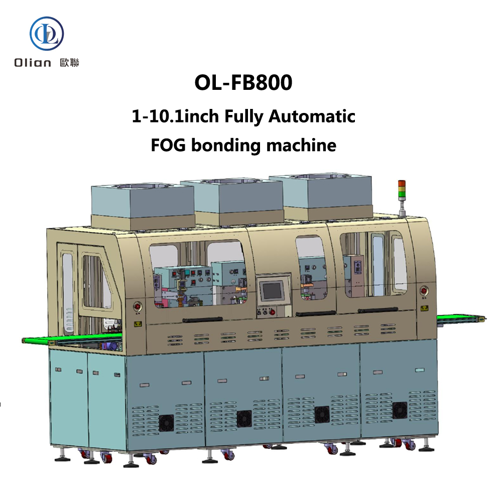
The OL-FB800 is a cutting-edge fully automatic FOG (Film on Glass) bonder designed to meet the precise requirements of modern electronics manufacturing. This advanced machine specializes in automatic ACF (Anisotropic Conductive Film) application, alignment, and thermal bonding for LCD products ranging from 1″ to 10.1″ in size, with single-sided, single FPC (Flexible Printed Circuit) components. Its innovative design and high-precision features make it an essential tool for manufacturers seeking efficiency, accuracy, and reliability in their production lines.

Equipment Information

  • Equipment Name: Fully Automatic FOG Bonder
  • Model: OL-FB800
  • Application: Suitable for LCD products with sizes from 1″ to 10.1″, designed for automatic ACF application, alignment, and thermal bonding of single-sided, single FPC.
  • Compatibility: Can be integrated with other machines in a production line for seamless operation.

Working Principle

The OL-FB800 operates through a series of coordinated mechanical and automated processes. The workflow begins with the loading of the product onto the conveyor belt or platform, either manually or via an automated upstream machine. Mechanical arm 0# picks up the LCD + COF, corrects its position using the CCD (Charge-Coupled Device) system, and places it on the ACF platform. The ACF platform advances, and the bonding head descends to apply the ACF. After the ACF application, the platform retracts for position detection to ensure proper ACF adhesion.

Next, mechanical arm 1# transfers the LCD + COF to the pre-bonding stage while the FPC is simultaneously loaded and pre-aligned on the carrier stage. The bonding head then picks up the FPC and performs the pre-bonding process. Mechanical arm 2# moves the product to one of the four main bonding platforms for final bonding. Finally, mechanical arm 3# transfers the bonded product to the downstream conveyor or production line.

Product Specifications

LCD Specifications

  • Size Range: Minimum 20mm x 20mm, Maximum 230mm x 165mm, Thickness 0.15mm to 1.1mm.
  • Alignment Marks: Pitch ≥ 5mm between any two points on the glass, Mark size 2mm to 100mm.

FPC Specifications

  • Size Range: Minimum 20mm x 10mm, Maximum 150mm x 122mm, Thickness 0.1mm to 0.5mm.
  • Terminal Pitch: ≥ 50µm.
  • Alignment Marks: Pitch 5mm to 70mm.
  • Note: FPC width is related to the bonding head length and can be customized according to customer requirements.

ACF Specifications

  • Types: Roll-based, 2-layer or 3-layer.
  • Application Length: 5mm to 80mm.
  • Application Width: Available in 0.8mm, 1.0mm, 1.5mm, 2.0mm, and 2.5mm widths, adjustable according to requirements.
  • Reel Specifications: Inner diameter options of 18mm and 25mm, Maximum reel diameter 200mm.

Buffer Material Specifications

  • ACF Section: Single-piece buffer material, manually clamped.
  • Main Bonding Section: Automatic front-to-back rotation.
  • Reel Dimensions: Outer diameter ≤ 100mm, Inner hole diameter 32mm.
  • Width: Adjustable from 5mm to 20mm.
  • Feed Frequency: Adjustable from 1 to 999 cycles for automatic tape rotation.
  • Feed Length: Single-step length adjustable from 1mm to 130mm.

Machine Performance

Production Accuracy

  • ACF Application Accuracy: ±0.2mm in X-axis, ±0.15mm in Y-axis.
  • FPC Pre-bonding Accuracy: ±7µm in X-axis, ±7µm in Y-axis.
  • FPC Main Bonding Accuracy: ±20µm in X-axis, ±20µm in Y-axis.

Production Cycle

  • Cycle Time: ≤ 4.5 seconds per piece.
  • ACF Application Time: ≤ 0.5 seconds.
  • Pre-bonding Time: ≤ 0.5 seconds.
  • Main Bonding Time: ≤ 12 seconds.

Product Type

  • Supported Type: Single-sided, single FPC.

Model Changeover

  • New Model Setup: ≤ 120 minutes.
  • Existing Model Recall: ≤ 60 minutes, depending on the operator’s proficiency.

Process Parameter Specifications

Temperature Control

  • Setting Range:
    • ACF-bonding: Room Temperature (RT) to 120°C.
    • Pre-bonding: RT to 80°C.
    • Main-bonding: RT to 400°C.
  • Heating Method: Constant heat.
  • Control Method: Touchscreen setting with 1°C increments, PID control.
  • Temperature Uniformity: ±5°C.
  • Thermocouple Type: K type.

Time Setting

  • Setting Range:
    • ACF-bonding: 0.1 to 9.9 seconds.
    • Pre-bonding: 0.1 to 9.9 seconds.
    • Main-bonding: 0.1 to 99.9 seconds.
  • Setting Method: Configured via touchscreen interface with 0.1-second increments.

Pressure Control

  • Adjustment Range:
    • ACF-bonding: 10 to 150N.
    • Pre-bonding: 10 to 150N.
    • Main-bonding: 20 to 400N.
  • Control Method: Precision pressure regulator with 0.001Mpa increments.

General Machine Specifications

Dimensions and Weight

  • Machine Length: Approximately 2800mm (including 1500mm conveyor extensions on both sides).
  • Machine Width: Approximately 1160mm.
  • Machine Height: Approximately 1800mm (excluding FFU and tri-color light).
  • Working Height: 1000mm.
  • Machine Weight: Approximately 2000kg.
  • Color: White, with customization options available.

Environmental and Power Requirements

  • Operating Environment: Class 1000 or lower cleanroom.
  • Power Supply: Single-phase 220VAC, with a 2-meter power cord for connection to factory power.
  • Power Consumption: Maximum 8KW.

Air and Vacuum Supply

  • Air Supply: Clean compressed air with a minimum pressure of 0.5-0.7MPa, consumption approximately 150L/min.
  • Vacuum Supply: Built-in vacuum pump (200L/min) and storage tank. Optional customer-provided vacuum source with a 12mm diameter hose connection. Vacuum level: ≥ -70Kpa (≥ 525mm Hg), flow approximately 150L/min.

Safety Features

  • Emergency Stop: Equipped with anti-misoperation covers.
  • Interlocked Design: Ensures machine safety during operation.
  • Audible and Visual Alarms: Alerts for errors or operator attention via the touchscreen.
  • Safety Labels: Warnings for electrical shock, mechanical injury, etc., in hazard areas.

Equipment Unit Specifications

Feeding and Discharging

  • Feeding: Conveyor belt loading.
  • Discharging: Conveyor belt unloading, direct handover to downstream machines.

Robotic Arms

  • Mechanical Arm 1# (from Conveyor to ACF Platform):
    • Vacuum nozzles with adjustable numbers and configurations based on product size.
    • Digital vacuum gauge for real-time monitoring.
    • X-axis: Servo motor drive.
    • θ-axis: Stepper motor.
    • Z-axis: Sliding table cylinder with manually adjustable position.
  • Mechanical Arm 2# (from ACF Stage to Pre-bonding Stage):
    • Vacuum nozzles with adjustable numbers and configurations based on product size.
    • Digital vacuum gauge for real-time monitoring.
    • X-axis: Servo motor drive.
    • Z-axis: Sliding table cylinder with manually adjustable position.
  • Mechanical Arm 3# (from Pre-bonding Stage to Main Bonding Stage):
    • Vacuum nozzles with adjustable numbers and configurations based on product size.
    • Digital vacuum gauge for real-time monitoring.
    • X-axis: Linear motor drive.
    • θ-axis: Stepper motor.
    • Z-axis: Sliding table cylinder with manually adjustable position.
  • Mechanical Arm 4# (from Main Bonding Stage to Discharge Conveyor):
    • Vacuum nozzles with adjustable numbers and configurations based on product size.
    • Digital vacuum gauge for real-time monitoring.
    • X-axis: Linear motor drive.
    • Z-axis: Cylinder with manually adjustable position.
    • Sliding table cylinder with manually adjustable position.

ACF Unit

  • ACF Cutter:
    • Cutting Method: Automatic semi-cutting.
    • Depth Adjustment: Micrometer fine adjustment.
    • Blade Movement: Cylinder-driven up and down, with adjustable X-axis position.
  • ACF Head:
    • Number of Bonding Heads: 1.
    • Drive Method: Cylinder + rail.
    • Pressure Control: Cylinder control with precision pressure regulator.
    • Material: SUS440C (customizable).
    • Dimensions: W 6mm × L 60mm (customizable).
    • Surface Flatness: ≤ 5µm.
  • ACF Stage:
    • Y-axis Movement: Servo motor + ball screw + rail.
    • Vacuum: 1mm hole diameter, 2mm vacuum slot width.
    • Material: Aluminum with anodized hard oxidation treatment.
    • Flatness: ±0.02mm.
  • ACF Backup:
    • Material: Quartz.
    • Dimensions: L100mm × W6mm × H18mm.
    • Surface Flatness: ≤ 5µm.
  • ACF Inspection: CCD inspection system.
  • ACF Supply:
    • Operation Method: Torque motor.
    • Reel Tensioning: Belt tensioning structure.
    • Protective Film Recovery: Vacuum吸取 to waste bin.
    • Separation Rod Movement: Cylinder-driven rod.

FPC Pre-bonding Unit

  • Pre-bonding Head:
    • Number of Bonding Heads: 1.
    • Z-axis Drive: Servo motor + ball screw + rail.
    • Y-axis Transmission: Servo motor + ball screw + rail.
    • Pressure Control: Cylinder control with precision pressure regulator.
    • Material: SUS 440C HRC58.
    • Dimensions: W 1.2mm × L 80mm (customizable).
    • Surface Flatness: ≤ ±5µm.
    • Vacuum: Segmentable vacuum selection with vacuum detection.
  • Pre-bonding Stage:
    • X-axis Movement: Servo motor + ball screw + rail.
    • Y-axis Movement: Servo motor + ball screw + rail.
    • θ-axis Movement: DD motor.
    • Vacuum: 1mm hole diameter, 2mm vacuum slot width.
    • Material: Aluminum with anodized hard oxidation treatment.
    • Flatness: ±0.02mm.
  • Pre-bonding Backup:
    • Material: SUS440C.
    • Dimensions: L100mm × W10mm × H12mm (customizable).
    • Surface Flatness: ≤ ±5µm.
  • FPC Supply Unit:
    • Loading Method: Manual FPC loading or automatic FPC loader (purchased separately).

FPC Main Bonding Unit

  • Main Bonding Head:
    • Number of Bonding Heads: 4.
    • Drive Method: Cylinder + rail.
    • Pressure Control: Cylinder control with precision pressure regulator.
    • Material: SUS440C.
    • Dimensions: W 1.0mm × L 60mm (customizable).
    • Surface Flatness: ≤ ±4µm.
  • Main Bonding Stage:
    • Y-axis Movement: Servo motor + ball screw.
    • Vacuum: 1mm hole diameter, 2mm vacuum slot width.
    • Material: Aluminum with anodized hard oxidation treatment.
    • Flatness: ±0.02mm.
  • Main Bonding Backup:
    • Material: Quartz strip.
    • Dimensions: L100mm × W6mm × H18mm.
    • Surface Flatness: ≤ ±5µm.
    • Vacuum position dimensions customized to product FPC size.
  • Buffer Material Supply:
    • Rotation Method: Stepper motor drive.
    • Rotation Direction: Automatic front-to-back rotation.
    • Width Adjustment: Manual width adjustment with limit wheel.
    • Sensor detection for tape end monitoring.

Image Processing Unit

  • LCD Correction:
    • System: Bosch image processing system.
    • CCD Camera: 1.
    • Coaxial Light Barrel: 1.
    • Magnification: 1x.
    • Field of View: 4.8mm × 3.6mm.
    • Light Source: Coaxial light LED.
    • Z-axis Adjustable Travel: 10mm.
  • ACF Inspection:
    • System: Bosch detection system.
    • CCD: 1.
    • Coaxial Light Barrel: 1.
    • Magnification: 0.5x.
    • Field of View: 9.6mm × 7.2mm.
    • Light Source: Coaxial light LED.
  • Pre-bonding Alignment:
    • System: Bosch image processing system.
    • CCD Cameras: 2.
    • Coaxial Light Barrels: 2.
    • Magnification: 2x.
    • Field of View: 2.4mm × 1.8mm.
    • Light Source: Coaxial light LED.
    • Alignment Method: Mark coincidence.

Control Unit

  • Control Method: PLC control.
  • Touchscreen:
    • Interface: Chinese, touch-enabled.
    • Modes: Manual and automatic.
    • Functions: Parameter display, data storage for 100 varieties.
  • Manual Control Buttons:
    • Emergency Stop Buttons: 3.
    • Main Power Switch: 1.
    • Lighting Power Switch: 1.
  • Access Control: Machine pauses when doors are opened during operation.
  • Operation Indicator Lights: Tri-color lights.

Documentation and After-sales Service

  • Documentation: Machine operation manual included.
  • Training: Covers installation, operation, calibration, maintenance, troubleshooting, and safety precautions.
  • After-sales Service: One year of free service for non-human-induced faults, with lifelong technical support.

Main Component Brands

  • Servo Motors: Fuji (Japan).
  • Angle Motors: Huichuan (Japan).
  • Linear Motors: Yakobes/Linea/Tongxin (China/China/China).
  • Ball Screws: THK/Hiwin/TBI (Japan/China/China).
  • Guideways: THK/Hiwin/TBI (Japan/China/China).
  • Pneumatic Components: SMC/Airtac (Japan/China).
  • PLC: Keyence (Japan).
  • Touchscreen: Proface (Japan).
  • Sensors: Panasonic/Huan (Japan/China).
  • Power Supply: Mean Well (China).
  • Circuit Breakers and Contactors: Schneider (China).
  • Drag Chains: Igus (Germany).
  • Emergency Stop and Switch Buttons: Schneider (China).
  • FFU (Stainless Steel): Yunfeng (China).

In summary, the OL-FB800 Fully Automatic FOG Bonder represents a significant advancement in the field of LCD manufacturing equipment. Its precise engineering, user-friendly design, and comprehensive support make it an ideal choice for manufacturers seeking to enhance productivity and product quality in the competitive electronics market.

is a highly efficient fully automatic LCD loader designed to continuously load LCD panels

OL-LLD2000 Fully Automatic Non-stop LCD Loader

OL-LLD2000 Fully Automatic Non-stop LCD Loader

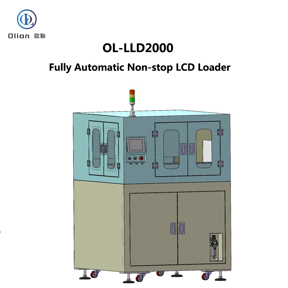
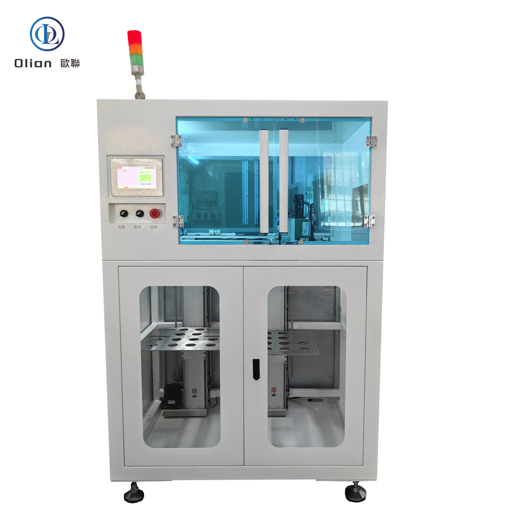
The OL-LLD2000 is a highly efficient fully automatic LCD loader designed to continuously load LCD panels of various sizes using a TRAY disk transmission method. This advanced machine can operate without stopping, making it a valuable addition to modern manufacturing environments where continuous production and high throughput are critical.

Equipment Information

  • Equipment Name: Fully Automatic Non-stop LCD Loader
  • Model: OL-LLD2000
  • Function: Loads LCD panels automatically via TRAY disk transmission, enabling non-stop operation.
  • Compatibility: Can be integrated with other devices for automated production lines.

Working Principle

The OL-LLD2000 operates through a well-coordinated process. It starts with manual placement of loaded TRAY disks (containing LCD panels) into the full tray buffer storage. The full tray loading station’s Z-axis descends to the pick-up position, and the full tray buffer storage’s Y-axis moves to the discharge position. The full tray loading station’s Z-axis then ascends to the discharge position. The product robotic arm picks up the LCD panels and hands them over to the downstream process. After the LCD panels are picked up, the material handling robotic arm moves the empty tray to the empty tray warehouse. When the empty tray warehouse is full, it is lowered to the inventory buffer storage for employees to remove the empty trays.

Product Specifications

LCD Specifications

  • Size Range: Minimum 45×72mm, Maximum 95×160mm.

Tray Disk Specifications

  • Dimensions: Maximum 400×520mm, Minimum 250×220mm.

Machine Performance

Production Cycle

  • Cycle Time: ≤3.5 seconds per piece, ensuring high throughput and efficiency.

General Machine Specifications

Dimensions and Weight

  • Machine Length: 1250mm.
  • Machine Width: 1300mm.
  • Machine Height: 1700mm (excluding tri-color light: 350mm).
  • Weight: Approximately 350kg.
  • Color: Off-white with chrome or oxidation treatment on some components (customizable to client requirements).

Environmental and Power Requirements

  • Operating Environment: Requires a clean, dust-free room.
  • Power Supply: Single-phase AC 220V±10%, 50 Hz, with a 2-meter power cord for connection to factory power.
  • Power Consumption: Maximum 2000W.

Air and Vacuum Supply

  • Air Supply: Clean compressed air with a minimum pressure of 0.5-0.7MPa, consumption approximately 100L/min.
  • Vacuum Supply: Minimum vacuum degree of -70Kpa, flow approximately 100L/min.

Safety Features

  • Emergency Stop: Equipped with anti-misoperation covers.
  • Interlocked Design: Ensures machine safety during operation.
  • Audible and Visual Alarms: Alerts for errors or operator attention via the touchscreen.
  • Safety Labels: Warnings for electrical shock, mechanical injury, etc., in hazard areas.

Equipment Unit Specifications

Full/Empty Tray Handling

  • Elevation Mechanism: Stepper motor + precision ball screw.
  • Tray Stacking: Up to 600mm in height on the elevation platform.
  • Positioning: Mechanical positioning for accuracy.

LCD Handling Robotic Arm

  • Drive: XY axes by servo motor, Z axis by cylinder.
  • Precision: ±0.05mm movement accuracy.
  • Vacuum System: Adjustable vacuum nozzles with digital vacuum gauge for real-time monitoring.

Control Unit

  • Control Method: PLC control for reliability.
  • Touchscreen: User-friendly Chinese interface with manual and automatic modes, displaying work parameters.
  • Manual Control Buttons: Includes emergency stop, main power, and control buttons.
  • Access Control: Machine pauses when doors are opened during operation.
  • Indicator Lights: Tri-color lights for machine status indication.

Training and After-sales Service

  • Training: Covers installation, operation, calibration, maintenance, troubleshooting, and safety precautions.
  • After-sales Service: One year of free service for non-human-induced faults, with lifelong technical support.

Main Component Brands

  • Servo and Stepper Motors: Rite (China).
  • Guideways: Hiwin (China).
  • Pneumatic Components: Airtac (China).
  • PLC: Panasonic (Japan).
  • Touchscreen: Proface (Japan).
  • Power Supply: Mean Well (China).
  • Circuit Breakers and Contactors: Shihlin (China).
  • Drag Chains: Igus (Germany).

In summary, the OL-LLD2000 Fully Automatic Non-stop LCD Loader is a state-of-the-art solution for LCD panel loading in modern manufacturing. Its continuous operation capability, precision, and user-friendly design make it an invaluable asset for electronics manufacturers looking to optimize their production processes and enhance product quality.

OL-FLD2000 Fully Automatic FPC Loader

OL-FLD2000 Fully Automatic FPC Loader

OL-FLD2000 Fully Automatic FPC Loader

The OL-FLD2000 is a highly efficient fully automatic FPC (Flexible Printed Circuit) loader designed to automatically feed FPCs of various sizes using a TRAY disk transmission method. This advanced machine can be integrated with FOG (Film on Glass) equipment for automated production lines, making it a valuable addition to modern manufacturing environments where precision and speed are critical.

Equipment Information

  • Equipment Name: Fully Automatic FPC Loader
  • Model: OL-FLD2000
  • Function: Loads FPCs automatically via TRAY disk transmission, compatible with FOG devices for integrated use.

Working Principle

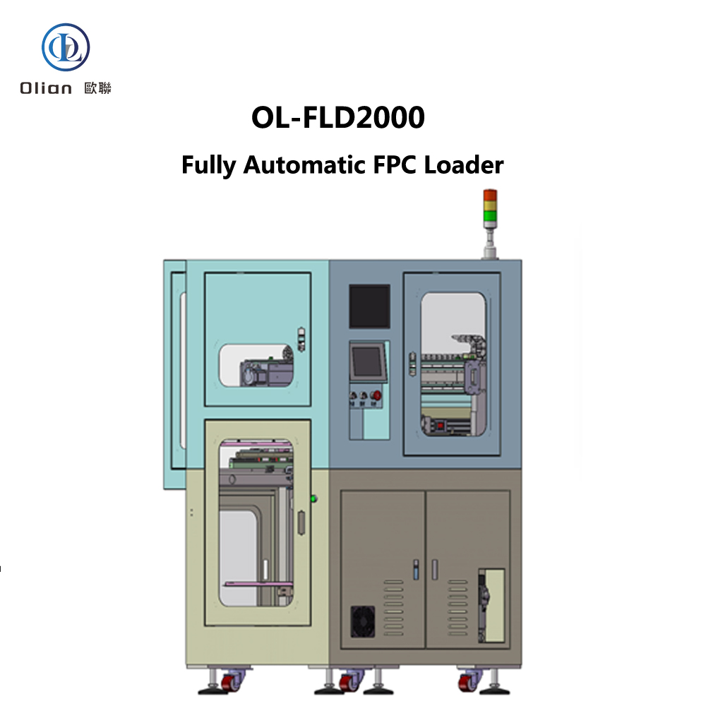
The OL-FLD2000 operates through a well-coordinated process. It starts with manual placement of loaded TRAY disks (containing FPCs) onto the loading position. The Tray loading handling Z-axis lifts a TRAY disk to the intermediate platform. After a full-view photo is taken, the FPC handling robotic arm picks up the FPC from the Tray and moves it to the discharge position. The Tray intermediate platform then moves to the unloading position, where the Tray unloading handling Z-axis removes the empty Tray and places it in the empty Tray unloading position, ensuring a continuous and efficient workflow.

Product Specifications

FPC Specifications

  • Size Range: Minimum 15×10mm, Maximum 100×175mm.

Tray Disk Specifications

  • Dimensions: Maximum 400×460mm, Minimum 250×220mm.

Machine Performance

Production Cycle

  • Cycle Time: ≤3.5 seconds per piece, ensuring high throughput and efficiency.

Handling Precision

  • Precision: ±0.03mm.

General Machine Specifications

Dimensions and Weight

  • Machine Length: 1100mm.
  • Machine Width: 1100mm (with a 240mm extension for the robotic arm).
  • Machine Height: 1760mm (excluding tri-color light: 350mm).
  • Weight: Approximately 400kg.
  • Color: Off-white with chrome or oxidation treatment on some components (customizable to client requirements).

Environmental and Power Requirements

  • Operating Environment: Requires a clean, dust-free room.
  • Power Supply: Single-phase AC 220V±10%, 50 Hz, with a 2-meter power cord for connection to factory power.
  • Power Consumption: Maximum 2000W.

Air and Vacuum Supply

  • Air Supply: Clean compressed air with a minimum pressure of 0.5-0.7MPa, consumption approximately 100L/min.
  • Vacuum Supply: Minimum vacuum degree of -70Kpa, flow approximately 100L/min.

Safety Features

  • Emergency Stop: Equipped with anti-misoperation covers.
  • Interlocked Design: Ensures machine safety during operation.
  • Audible and Visual Alarms: Alerts for errors or operator attention via the touchscreen.
  • Safety Labels: Warnings for electrical shock, mechanical injury, etc., in hazard areas.

Equipment Unit Specifications

Full/Empty Tray Handling

  • Elevation Mechanism: Servo motor + precision ball screw.
  • Tray Stacking: Up to 500mm in height on the elevation platform.
  • Positioning: Mechanical positioning for accuracy.

Tray X-axis Intermediate Transfer

  • Positioning: Mechanical positioning for Tray disks.
  • Drive: Servo motor with ball screw transmission, using precision linear guides.
  • Precision: ±0.02mm movement accuracy.

Tray Disk Handling Structure

  • Drive: Cylinder-driven.
  • Vacuum System: Adjustable vacuum nozzles with digital vacuum gauge for real-time monitoring.

FPC XYZθ Handling Robotic Arm

  • Drive: XZ axes by servo motor, θ-axis by stepper motor, Y-axis by linear motor.
  • Precision: ±0.05mm movement accuracy.
  • Vacuum System: Adjustable vacuum nozzles with digital vacuum gauge for real-time monitoring.

Control Unit

  • Control Method: PLC control for reliability.
  • Touchscreen: User-friendly Chinese interface with manual and automatic modes, displaying work parameters.
  • Manual Control Buttons: Includes emergency stop, main power, and control buttons.
  • Access Control: Machine pauses when doors are opened during operation.
  • Indicator Lights: Tri-color lights for machine status indication.

Training and After-sales Service

  • Training: Covers installation, operation, calibration, maintenance, troubleshooting, and safety precautions.
  • After-sales Service: One year of free service for non-human-induced faults, with lifelong technical support.

Main Component Brands

  • Servo and Stepper Motors: Rite (China).
  • Guideways: Hiwin (China).
  • Pneumatic Components: Airtac (China).
  • PLC: Panasonic (Japan).
  • Touchscreen: Proface (Japan).
  • Power Supply: Mean Well (China).
  • Circuit Breakers and Contactors: Shihlin (China).
  • Drag Chains: Igus (Germany).

In summary, the OL-FLD2000 Fully Automatic FPC Loader is a state-of-the-art solution for FPC loading in modern manufacturing. Its precision, speed, and user-friendly design make it an invaluable asset for electronics manufacturers looking to optimize their production processes and enhance product quality.

OL-EC2000 Fully Automatic Terminal Cleaning Machine

OL-EC2000 Fully Automatic Terminal Cleaning Machine

OL-EC2000 Fully Automatic Terminal Cleaning Machine

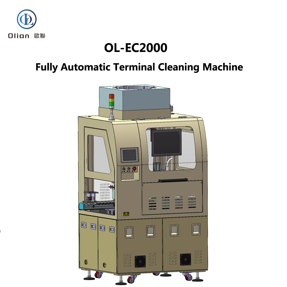
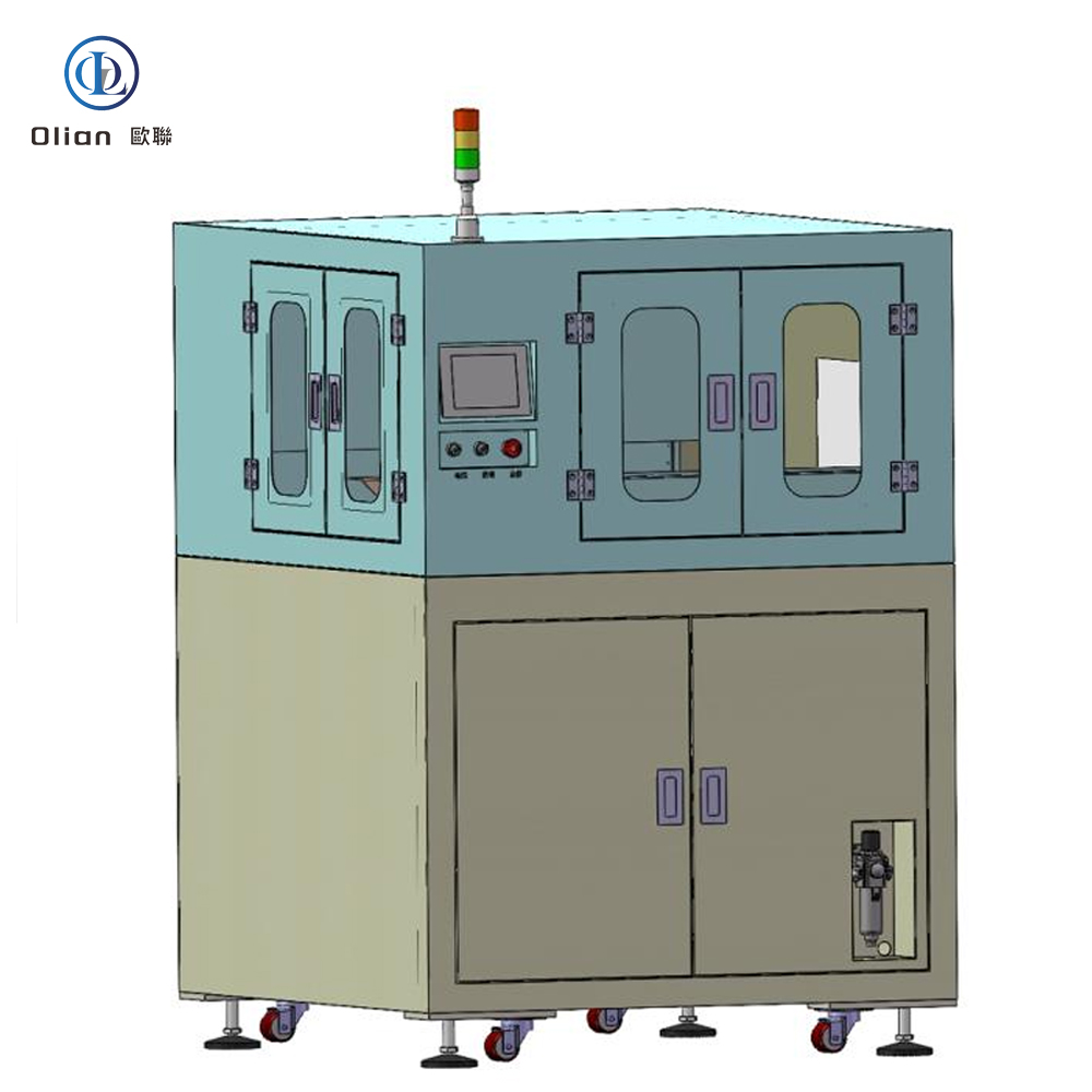
The OL-EC2000 is a cutting-edge fully automatic terminal cleaning machine designed to efficiently clean LCD products of various sizes (1-7 inches) through wiping, cleaning (with optional ultrasonic cleaning), and plasma treatment. This advanced equipment can be integrated with other devices in a production line, making it a valuable addition to modern manufacturing environments where precision and speed are paramount.

Equipment Information

  • Equipment Name: Fully Automatic Terminal Cleaning Machine
  • Model: OL-EC2000
  • Function: Automatically cleans LCD products through wiping, cleaning, and plasma treatment, and can be connected with other equipment for automated production lines.

Working Principle

The OL-EC2000 operates through a series of automated processes. It starts with manual placement of the LCD onto a platform or conveyor belt. Robotic arm 1# then moves the LCD to a CCD correction station for position adjustment. The LCD is transferred to a wiping platform where it is cleaned by a wiping head. After wiping, robotic arm 2# transports the LCD to a plasma cleaning platform for further cleaning. Finally, the cleaned LCD is moved to a discharge station.

Product Specifications

LCD Specifications

  • Size Range: 1-7 inches.

Cleaning Cloth Specifications

  • Type: Roll-based (number of rolls: 2).
  • Width: ≤ 10mm.
  • Maximum Roll Diameter: ≤ 300mm.
  • Roll Inner Hole Diameter: ≥ 24.5mm.
  • Feed Length: Adjustable from 0.1mm to 99.9mm.

Cleaning Solvent

  • Type: Alcohol or acetone.

Machine Performance

Production Cycle

  • Cycle Time: ≤ 3.5 seconds per piece (wiping speed ≥ 60mm/s).

Handling Precision

  • Precision: ±0.1mm.

Water Drop Angle

  • Water Drop Angle: ≤ 20 degrees, depending on actual conditions.

Product Type

  • Supported Type: Single-edge terminal double-sided cleaning.

Model Changeover

  • New Model Setup: ≤ 30 minutes.
  • Existing Model Recall: ≤ 15 minutes, depending on the operator’s proficiency.

General Machine Specifications

Dimensions and Weight

  • Machine Length: 1100mm.
  • Machine Width: 950mm.
  • Machine Height: 1800mm (excluding tri-color light: 350mm).
  • Weight: Approximately 1000kg.
  • Color: Components with black hard anodizing, frame in off-white (customizable to client requirements).

Environmental and Power Requirements

  • Operating Environment: Requires a clean, dust-free room.
  • Power Supply: Single-phase 220V, with a 3-meter power cord for connection to factory power.
  • Power Consumption: Maximum 3KW.

Air and Vacuum Supply

  • Air Supply: Clean compressed air with a minimum pressure of 0.5-0.7MPa, consumption ≤ 220L/min.
  • Vacuum Supply: Built-in vacuum pump (200L/min) and storage tank. Optional customer-provided vacuum source with a 12mm diameter hose connection. Vacuum level: ≥ -70Kpa (≥ 525mm Hg), flow ≥ -700L/min.

Safety Features

  • Emergency Stop: Equipped with anti-misoperation covers.
  • Interlocked Design: Ensures machine safety during operation.
  • Audible and Visual Alarms: Alerts for errors or operator attention via the touchscreen.
  • Safety Labels: Warnings for electrical shock, mechanical injury, etc., in hazard areas.

Equipment Unit Specifications

CCD Correction

  • Correction Method: Camera photography with automatic correction.

Solvent Supply Unit

  • Solvent Control: Dosed by peristaltic dispensing equipment.
  • Solvent Drop Volume: Adjustable per drop.

Cleaning Cloth Supply Unit

  • Cleaning Cloth Movement: Stepper motor + polyurethane roller.
  • Cleaning Cloth Tensioning: Magnetic damping, adjustable force.
  • Cleaning Cloth Recycling: Torque motor + magnetic damping, roll-based recycling.
  • Cleaning Cloth Length Control: Stepper motor, adjustable length via operation interface.
  • End-of-Tape Detection: Sensor detects when the cleaning cloth roll is finished.

Cleaning Air Claw Unit

  • Air Claw Gap Height: Adjustable via micrometer, travel 5mm.
  • Air Claw Flatness: Adjustable relative flatness of upper and lower clamping surfaces.

PLAMA Unit

  • Plasma Cleaning: Low-temperature plasma, measured around 100°C.

Robotic Arms

  • 搬运机械手:
    • Vacuum nozzles with adjustable numbers and configurations based on product size.
    • Digital vacuum gauge for real-time monitoring.
    • X-axis: Servo motor + rail.
    • Z-axis: Cylinder with manually adjustable position.
    • θ-axis: Stepper motor.

Stage and Plasma Sections

  • X-axis Movement: Servo motor + ball screw + rail.
  • Y-axis Movement: Servo motor + ball screw + rail.
  • Platform Material: Aluminum with black hard anodizing.
  • Platform Flatness: ±0.02mm.
  • Vacuum Suction Circuits: Multiple sets on the platform for different LCD sizes.

Control Unit

  • Control Method: PLC control.
  • Touchscreen:
    • Interface: Chinese, touch-enabled.
    • Modes: Manual and automatic.
    • Functions: Parameter display.
  • Manual Control Buttons:
    • Emergency Stop Button: 1.
    • Main Power Switch: 1.
  • Access Control: Machine pauses when doors are opened during operation.
  • Operation Indicator Lights: Tri-color lights (customizable to client requirements).
  • Monitor: Displays visual alignment images.

Documentation and After-sales Service

  • Documentation: Machine operation manual included.
  • Training: Covers installation, operation, calibration, maintenance, troubleshooting, and safety precautions.
  • After-sales Service: One year of free service for non-human-induced faults, with lifelong technical support.

Main Component Brands

  • Servo and Stepper Motors: Rite (China).
  • Guideways: SKD (China).
  • Pneumatic Components: CKD/Airtac (Japan/China).
  • PLC: Keyence/Panasonic (Japan).
  • Touchscreen: Proface (Japan).
  • Power Supply: Mean Well (Taiwan).
  • Circuit Breakers and Contactors: Shihlin/Schneider (Taiwan).
  • Drag Chains: Igus (Germany).

In summary, the OL-EC2000 Fully Automatic Terminal Cleaning Machine represents a significant advancement in LCD manufacturing equipment. Its precise engineering, user-friendly design, and comprehensive support make it an ideal choice for manufacturers seeking to enhance productivity and product quality in the competitive electronics market.